TB6600HG Stepper Motor Driver: Specifications, Features and Applications
Catalog
TB6600HG description
TB6600HG is a PWM chopper type single-chip bipolar sinusoidal microstepping motor driver. It can achieve forward and reverse rotation control through 2-phase, 1-2-phase, W1-2-phase, 2W1-2-phase, and 4W1-2-phase excitation modes. 2-phase bipolar stepper motors are driven solely by a low-vibration, high-efficiency clock signal.
Alternatives and equivalents:
• TB6600FG
• L6258EX
Specifications of TB6600HG
• Part Status: Active
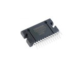
• Packaging: Tray
• Package / Case: HZIP-25
• Manufacturer: Toshiba
• Operating Supply Current: 4.2 mA
• Operating Supply Voltage: 2 V to 5.5 V
• Load Voltage Rating: 8 V to 42 V
• Number of Outputs: 2 Outputs
• Pd - Power Dissipation: 40 W
• Mounting Style: Through Hole
• Package Length/Width/Height: 29.3mm(Max)/4.5mm/15.7mm
• Product Category: Motor / Motion / Ignition Controllers & Drivers
Operating conditions of TB6600HG
(TA = -30°C to 85°C)
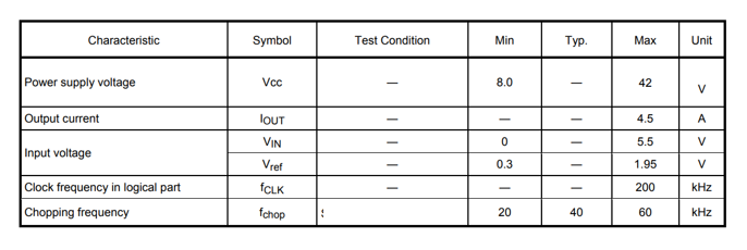
Note: Two Vcc terminals should be programmed the same voltage. The maximum current of the operating range can not be necessarily conducted depending on various conditions because output current is limited by the power dissipation PD. Make sure to avoid using the IC in the condition that would cause the temperature to exceed Tj (avg.) =107°C.
The power supply voltage of 42 V and the output current of 4.5 A are the maximum values of operating range. Please design the circuit with enough derating within this range by considering the power supply variation, the external resistance, and the electrical characteristics of the IC. In case of exceeding the power supply voltage of 42 V and the output current of 4.5 A, the IC will not operate normally.
How to connect TB6600HG to the control system?
Power connection: First, make sure to provide appropriate power supply to TB6600HG. When powering TB6600HG, you usually need to connect two pins: VCC (positive power supply) and GND (ground wire). The VCC pin is responsible for providing the voltage required to drive the chip, while the GND pin serves as the reference ground level. We need to ensure that the power supply is stable and meets the specifications of the TB6600HG.
Signal connection: According to the specific needs of the control system, we need to connect the control signal to the corresponding pin of the TB6600HG driver chip. These control signals usually include direction control signals and step pulse signals, etc., which are responsible for instructing how the motor acts, including the direction of rotation and the speed of rotation.
Motor connection: We need to be particularly careful when connecting the motor to the TB6600HG driver chip. The two wires of the motor, usually red and black, represent the positive and negative poles of the motor respectively. The red wire usually connects to the positive terminal of the motor, while the black wire connects to the negative terminal.
Feedback connection (optional): If an encoder is used for feedback control, we also need to connect the output signal of the encoder to the control system. This typically includes the outputs of Phase A, Phase B, and Phase Z (if available).
Grounding: We need to ensure that the common ground wire of all equipment is connected correctly to avoid interference and damage.
Initialization settings: After the connection is complete, we need to initialize the settings of the TB6600HG to ensure that it works correctly. This may include setting current limits, stepping modes, etc.
TB6600HG product features
• Adopt an enlarged radiator for good heat dissipation
• Subdivision setup instructions are printed on the back of the board
• With output short circuit protection function, worry-free use
• Adopt 6N137 high-speed optical coupling to ensure high speed without loss of synchronization
• Output current is steplessly adjustable to meet your various application needs
• Using common anode input mode, there are two input terminals, making wiring more convenient
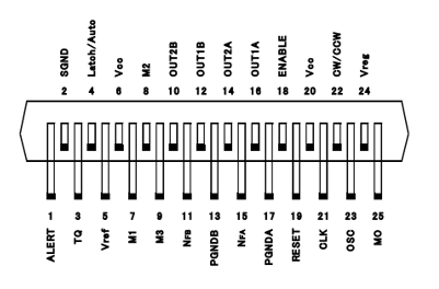
Pin configuration of TB6600HG
Function description of TB6600HG
Excitation settings
The excitation mode can be selected from the following eight modes using the M1, M2 and M3 inputs. When M1, M2, or M3 inputs are shifted during motor operation, a new excitation mode initiates from the initial mode, potentially disrupting the continuity of the output current waveform.
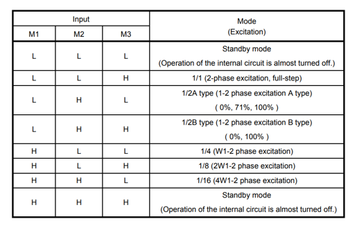
Note: To change the exciting mode by changing M1, M2, and M3, make sure not to set M1 = M2 = M3 = L or M1 = M2 = M3 = H.
Standby mode
The operation mode moves to the standby mode under the condition M1 = M2 = M3 = L or M1 = M2 = M3 = H. The power consumption is minimized by turning off all the operations except protecting operation. In standby mode, output terminal MO is HZ. Standby mode is released by changing the state of M1=M2=M3=L and M1=M2=M3=H to other state. Input signal is not accepted for about 200 μs after releasing the standby mode.
Decay mode
Charging and discharging a current in PWM mode typically require about five cycles in OSCM. The 40 percent fast decay mode is initiated by inducing decay within the final two cycles of fast decay mode, with the ratio of 40 percent remaining consistently fixed. The relation between the master clock frequency (fMCLK), the OSCM frequency (fOSCM) and the PWM frequency (fchop) is shown as follows:
fOSCM = 1/20×fMCLK
fchop = 1/100×fMCLK
When Rosc=51kΩ, the master clock=4MHz, OSCM=200kHz, the frequency of PWM(fchop)=40kHz.
Initial mode
When RESET is used, the phase currents are as follows.
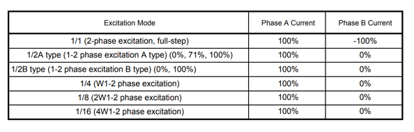
Current direction is defined as follows.
OUT1A → OUT2A: Forward direction
OUT1B → OUT2B: Forward direction
Application of TB6600HG
Listed below are some applications of TB6600HG.
• Tail lights
• Hospitality buildings
• Large outdoor LED display
• Alternative to HID lights
• Industrial high-bay lights
• Large format LED backlighting
• Display LED backlighting
• Camera-enabled smartphones
• Step-up or step-down driver topologies
Common faults and solutions of TB6600HG
The following lists some common faults about TB6600HG and their solutions to help you take quick action when encountering faults and safeguard the normal operation of the device.
Failure one: Driver chip overheating
The TB6600HG chip itself is too hot, probably due to excessive load or poor heat dissipation conditions.
Solution: Enhance heat dissipation
We need to add heat sinks or fans on the driver chip and motor to ensure that they can fully dissipate heat while working. At the same time, we need to keep the environment around the driver chip and motor well ventilated to avoid overheating.
Failure two: Motor rotates in the wrong direction
After the motor receives the drive signal, the direction of rotation is not in line with the expected, it may be the control signal is wrong or the drive chip is not properly configured.
Solution: Check the control signal
We need to carefully check the control signals sent to the TB6600HG to ensure that the direction control signal and pulse signal are correct. If a microcontroller is used to send the signals, please check the program code and pin configuration.
Failure three: Motor fails to rotate
The motor does not respond after receiving the drive signal, it may be that the driver chip is not working properly or there is a problem with the connection between the motor and the driver chip.
Solution: Check the power supply and connection
We need to make sure that the power supply of the TB6600HG is normal and the connection between the motor and the driver chip is solid. We check the voltage and current in the circuit by using a multimeter to make sure they are in the normal range.
Failure four: Serious motor heating
The motor generates excessive heat during operation, which may be caused by excessive current or poor heat dissipation.
Solution: Adjust the current setting
If the motor is generating serious heat, we can try to reduce the output current of the driver chip. By adjusting the current setting pin of TB6600HG, we can effectively limit the size of the output current, which in turn reduces the burden on the motor and ensures stable and safe operation of the motor.
Frequently Asked Questions [FAQ]
1. What is the operating temperature range of TB6600HG?
The operating temperature of TB6600HG ranges from -30°C to 85°C.
2. What is TB6600HG?
TB6600HG is a type of stepper motor driver, designed to control stepper motors in various applications such as CNC machines, 3D printers, robotics, and automation systems.
3. What are the key features of TB6600HG?
TB6600HG features include adjustable motor current, step resolution settings, built-in overheating protection, and opto-isolated inputs for signal control.
About us
ALLELCO LIMITED
Read more
Quick inquiry
Please send an inquiry, we will respond immediately.
Detailed Analysis and Application Guide for the UCC27517DBVR High Performance Low Side Driver
on September 3th
STM32F030K6T6 Comprehensive Guide: High Performance ARM Cortex-M0 Microcontrollers
on September 3th
Popular Posts
-

What is GND in the circuit?
on January 1th 3272
-

RJ-45 Connector Guide: RJ-45 Connector Color Codes, Wiring Schemes, R-J45 Applications, RJ-45 Datasheets
on January 1th 2815
-

Understanding Power Supply Voltages in Electronics VCC, VDD, VEE, VSS, and GND
on November 20th 2642
-

Fiber Connector Types: SC Vs LC And LC Vs MTP
on January 1th 2265
-

Comparison Between DB9 and RS232
on January 1th 1882
-

What Is An LR44 Battery?
Electricity, that ubiquitous force, quietly permeates every aspect of our daily lives, from trivial gadgets to life-threatening medical equipment, it plays a silent role. However, truly grasping this energy, especially how to store and efficiently output it, is no easy task. It is against this background that this article will focus on a type of coin cell battery that may seem insignificant on the...on January 1th 1846
-

Understanding the Fundamentals:Inductance Resistance, andCapacitance
In the intricate dance of electrical engineering, a trio of fundamental elements takes center stage: inductance, resistance, and capacitance. Each bears unique traits that dictate the dynamic rhythms of electronic circuits. Here, we embark on a journey to decipher the complexities of these components, to uncover their distinct roles and practical uses within the vast electrical orchestra. Inductan...on January 1th 1808
-

What Is RF and Why Do We Use It?
Radio Frequency (RF) technology is a key part of modern wireless communication, enabling data transmission over long distances without physical connections. This article delves into the basics of RF, explaining how electromagnetic radiation (EMR) makes RF communication possible. We will explore the principles of EMR, the creation and control of RF signals, and their wide-ranging uses. The article ...on January 1th 1801
-

CR2430 Battery Comprehensive Guide: Specifications, Applications and Comparison to CR2032 Batteries
What is CR2430 battery ?Benefits of CR2430 BatteriesNormCR2430 Battery ApplicationsCR2430 EquivalentCR2430 VS CR2032Battery CR2430 SizeWhat to look for when buying the CR2430 and equivalentsData Sheet PDFFrequently Asked Questions Batteries are the heart of small electronic devices. Among the many types available, coin cells play a crucial role, commonly found in calculators, remote controls, and ...on January 1th 1799
-

Comprehensive guide to hFE in transistors
Transistors are crucial components in modern electronic devices, enabling signal amplification and control. This article delves into the knowledge surrounding hFE, including how to select a transistor's hFE value, how to find hFE, and the gain of different types of transistors. Through our exploration of hFE, we gain a deeper understanding of how transistors work and their role in electronic circu...on November 20th 1782
HOT Part Number
-

VE-221-IY
Vicor Corporation
DC DC CONVERTER 12V 50W
TMP461AIRUNT-S
Texas Instruments
TEMPERATURE SENSOR
LM2575-5.0BT
Microchip Technology
IC REG BUCK 5V 1A TO220-5
BZW04-33
Diotec Semiconductor
TVS DO-15 33.3V 400W UNI
STCS05ADR
STMicroelectronics
IC LED DRVR LIN PWM 500MA 8SOIC
DS90CR281MTDX
Texas Instruments
IC INTERFACE SPECIALIZED 56TSSOP
PIC18F26K20-E/ML
Microchip Technology
IC MCU 8BIT 64KB FLASH 28QFN
MT28EW512ABA1HPC-0AAT
Micron Technology Inc.
IC FLASH 512MBIT PARALLEL 64LBGA
P3203ACL
Littelfuse Inc.
THYRISTOR 270V 400A TO220-3
100331PC
Fairchild Semiconductor
D FLIP-FLOP, 100K SERIES
V15P45HM3_A/I
Vishay General Semiconductor - Diodes Division
DIODE SCHOTTKY 45V 15A TO277A
FSMD500-16-2920R
RFE/Fuzetec
RESETTABLE FUSE - SMD, 2920 SIZE
KSP94BU
onsemi
TRANS PNP 400V 0.3A TO92-3
ADC122S021CIMM
Texas Instruments
IC ADC 12BIT SAR 8VSSOP
NTE5823
NTE Electronics, Inc
DIODE GEN PURP 600V 12A DO4
SN74HC244APWR
Texas Instruments
SETUP FOR IBM ORDERS
S912XET256BCAGR
NXP USA Inc.
IC MCU 16BIT 256KB FLASH 144LQFP
SN65HVD20D
Texas Instruments
IC TRANSCEIVER HALF 1/1 8SOIC -
NC7SZ86P5X
onsemi
IC GATE XOR 1CH 2-INP SC70-5
CD74AC540M
Texas Instruments
IC BUFFER INVERT 5.5V 20SOIC
SI4420DY
onsemi
MOSFET N-CH 30V 12.5A 8SOIC
LTC6908IS6-1#TRPBF
Analog Devices Inc.
IC OSC SILICON PROG TSOT23-6
LM2593HVSX-5.0
Texas Instruments
IC REG BUCK 5V 2A TO263-7
LT3757EDD#PBF
Analog Devices Inc.
IC REG CTRLR MULT TOPOLOGY 10DFN
BQ77908DBTR
Texas Instruments
IC BAT MFUNC LI-ION 4-8C 38TSSOP
MP2331HGTL-Z
Monolithic Power Systems Inc.
HIGH-EFFICIENCY, 2A, 24V, 1200KH
BAS20LT1
onsemi
DIODE SWITCH 200MA 200V SOT23
TC4425COE
Microchip Technology
IC GATE DRVR LOW-SIDE 16SOIC
1N2275
Microchip Technology
DIODE GEN PURP 300V 6A DO5
S9S12XS256J0CAL
NXP USA Inc.
IC MCU 16BIT 256KB FLASH 112LQFP
SI3453DV-T1-GE3
Vishay Siliconix
MOSFET P-CHANNEL 30V 3.4A 6TSOP
P3100EAL
Littelfuse Inc.
THYRISTOR 275V 150A TO226-2
AWT6277RM20P8
Skyworks Solutions Inc.
IC RF AMPLIFIER SMD
12063A392KAT2A
KYOCERA AVX
CAP CER 3900PF 25V NP0 1206
CRCW1206560RFKEA
Vishay Dale
RES SMD 560 OHM 1% 1/4W 1206
AXH010A0Y-SR
ABB Power Electronics Inc.
DC DC CONVERTER 1.8V 18W -
OPA234EA/2K5
Texas Instruments
IC OPAMP GP 1 CIRCUIT 8VSSOP
71M6543F-IGT/F
Analog Devices Inc./Maxim Integrated
IC ENERGY METERING
DAC6311IDCKR
Texas Instruments
IC DAC 10BIT V-OUT SC70-6
SPC560P40L3CEFBR
STMicroelectronics
IC MCU 32BIT 256KB FLASH 100LQFP
PIC18LF2321-I/SP
Microchip Technology
IC MCU 8BIT 8KB FLASH 28SPDIP
A10376
Antenova
AMIA ANTENNA CELLULAR SMD
FAN604HMX
onsemi
IC OFFLINE SWITCH FLYBACK 10SOIC
TPS75925KCG3
Texas Instruments
IC REG LINEAR 2.5V 7.5A TO220-5
TCFGA1C475M8R
Rohm Semiconductor
CAP TANT 4.7UF 20% 16V 1206
LTC1643AHIGN#PBF
Analog Devices Inc.
IC HOT SWAP CTR MOTHERBRD 16SSOP
SX33L_R1_00001
Panjit International Inc.
DIODE SCHOTTKY 30V 3A SMA
C0603JB0J334M030BC
TDK Corporation
CAP CER 0.33UF 6.3V JB 0201
VJ2220Y222KXUSTX1
Vishay Vitramon
CAP CER 2200PF 250VAC X7R 2220
CAT5137SDI-00GT3
onsemi
IC DGT POT 100KOHM 128TAP SC70-6
SN74LS352N
Motorola
MUX 1-ELEMENT BIPOLAR 8-IN
MC100EP52DR2
onsemi
IC FLIP FLOP ECL DATA/CLK 8-SOIC
S103K75Y5PN83K0R
Vishay Beyschlag/Draloric/BC Components
CAP CER 10000PF 1KV Y5P RADIAL
FQB12N50TM
Fairchild Semiconductor
TRANS MOSFET N-CH 500V 12.1A 3PI