Introduction to Gas Sensors: Construction, Types and Working
Gas sensors are best devices in modern technology, in monitoring and detecting various gases across a multitude of environments. Their ability to convert gas levels into electrical signals through physical or chemical reactions makes them valuable for applications ranging from industrial safety to household security.This article discusses into the different types of gas sensors, exploring their working principles, advantages, and limitations. Examining the components and functionalities of these sensors, particularly the widely used metal oxide gas sensors, we can appreciate their significance in ensuring safety, maintaining air quality, and supporting various industrial processes. Understanding the practical usage, calibration, and maintenance of these sensors enhances their reliability and accuracy, making them top tools in both professional and domestic settings.
Catalog
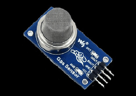
Figure 1: Gas Sensor
What is a Gas Sensor?
A Gas Sensors is a device designed to detect the presence or concentration of gases in an environment. It operates by measuring changes in the resistance of its internal material, which generates a voltage difference. This voltage difference helps identify and estimate the type and amount of gas present. The specific gases a sensor can detect depend on the material it is made from.
Gas sensors convert gas levels into electrical signals through physical or chemical reactions. These signals are processed to provide readable data. They are particularly useful for detecting toxic and harmful gases, as well as natural gas leaks. Gas sensors measure combustible, flammable, and toxic gases, and even oxygen levels, making them good for safety and air quality monitoring.
Standard for Gas Sensor Performance
When selecting gas sensors, it's a must to carefully evaluate several key measurement specifications to ensure their effectiveness and accuracy in gas detection applications. These specifications are criteria for the sensor's performance, especially in settings where safety is a top priority and in process control systems.
Response Time
Response time is the interval between the gas's initial contact with the sensor and the sensor's subsequent signal processing. This parameter requiring immediate gas detection to prevent hazardous incidents or maintain process integrity. Shorter response times are preferred in environments where quick detection can reduce risks, such as chemical plants or confined spaces with potential gas leaks. In practical operations, a gas sensor with a response time of less than 10 seconds is ideal for detecting sudden leaks. This allows for quick response actions, like evacuation or system shutdown.
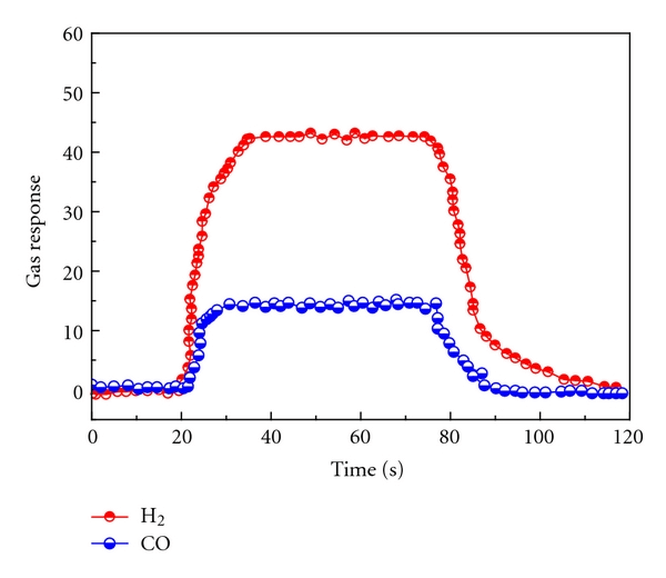
Figure 2: Response and Recovery Time of the Gas Sensor
Detection Distance
Detection distance is the maximum range at which the sensor can effectively detect gas from its source or leak. This specification dictates where sensors should be placed to ensure comprehensive monitoring. In large industrial setups, sensors must be positioned strategically to cover the entire facility, ensuring that even minor gas emissions are detected before escalating to dangerous levels. For example, sensors with a detection distance of 1-2 meters are often placed near potential leak points, while those with greater ranges (up to 10 meters) can monitor broader areas from central locations.
Flow Rate
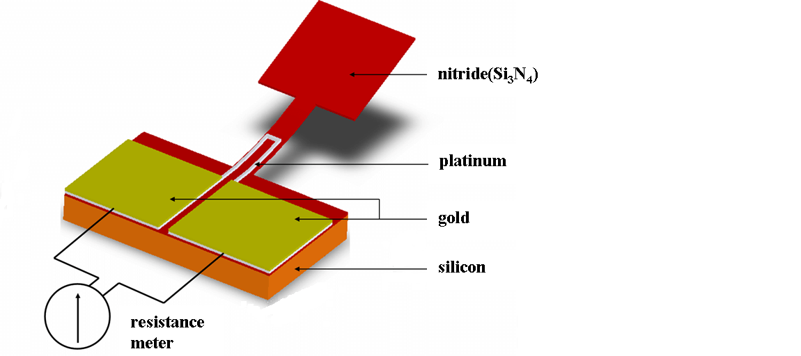
Figure 3: Schematic Illustration of Gas Flow Sensor
Flow rate represents the volume of air or gas that must flow across the sensor to generate a detectable signal. To guarantee precise readings of the gas concentration, this rate needs to be set properly. Inadequate flow rates can lead to delayed detection or false positives, compromising safety and operational efficiency. Operators may adjust ventilation systems or use auxiliary fans to maintain optimal flow rates across sensors. Ensuring a flow rate of 0.5 to 2 liters per minute across the sensor can significantly enhance detection accuracy in environments with variable airflow conditions.
Sensor Output Parameter
Gas sensors measure and report detected gases in various formats to meet different monitoring needs.
Percent LEL (Lower Explosive Limit)
Measures the smallest concentration of a combustible gas that can sustain a flame when mixed with air and ignited. Needed for safety in environments with explosive gases. A reading of 0% LEL indicates no gas present, while 100% LEL means the gas concentration has reached its flammable limit, posing a significant explosion risk. Operators monitor LEL to ensure gas levels stay below dangerous thresholds. Regular checks and immediate action on high readings to prevent accidents.
Percent Volume
Calculates the volume of the solute divided by the total volume of all components, multiplied by 100%. Less common for gas detection but helpful for applications involving gas-liquid interactions. Accurate measurement of gas concentrations in liquid mixtures helps in quality control and process optimization.
Parts Per Million (ppm)
Measures gas concentrations in ppm, allowing precise monitoring of very low gas levels. Required for detecting trace gases in environmental monitoring and quality control. Continuous monitoring ensures compliance with safety and environmental regulations. Small fluctuations are tracked to identify potential issues early.
Leakage Measurements (ml/min)
Indicates the rate at which gas escapes from a system. It helps identify and quantify leaks. By using this information, operators can ensure system integrity, avoid large losses, and perform maintenance and repairs on time.
Consumption Measurements (ml/L/hr.)
Reflects the rate at which a gas is consumed in a process. Excellent for use in industrial processes and biological research, for instance. It is possible to identify inefficiencies and optimize processes by keeping an eye on gas consumption rates.
Density Measurements (mg/m³)
Provides insights into the gas's physical properties in a given volume. Useful in pollution control and air quality assessment. Ensures adherence with environmental standards and aids in designing effective pollution control strategies.
Signature or Spectra Measurements
Offers a spectral signature of the gases present, often displayed as a chromatogram. Used in advanced analytical techniques like gas chromatography. Detailed analysis of gas composition and concentration helps identify contaminants and ensure product purity.
These signals are processed to provide real-time data on gas concentrations, aiding automated control systems.
|
COMMON OUTPUT SIGNALS FROM GAS SENSORS |
FUNCTIONS |
|
Analog Voltage |
a continuous electrical signal representing variable information |
|
Pulse Signals |
brief bursts of energy used for timing and synchronization |
|
Analog Currents |
electrical currents varying in magnitude to convey information |
|
Switch or Relay Outputs |
mechanisms that open or close circuits to control electrical flow |
Chart 1: Gas Sensor Output Signal and Functions
Types of Gas Sensor Based on Working Principles
Gas sensors are categorized by their operating principles. Each type has distinct characteristics, advantages, and drawbacks, making them suitable for various applications and environments.
Semiconductor / Metal Oxide-based Gas Sensor

Figure 4: Schematic Semiconductor / Metal Oxide-based Gas Sensor Parts
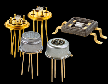
Figure 5: Semiconductor Gas Sensor Actual
These sensors identify gases by tracking the variations in resistance of a semiconductor when it comes into contact with gases. Commonly, they incorporate a metal oxide sensing component, like tin dioxide (SnO2), placed on a substrate equipped with electrodes and a heating element. The porous nature of the metal oxide layer increases the surface area available for gas interactions. As gases are adsorbed onto this layer, changes occur in the sensor’s electrical conductivity, which in turn modifies its resistance. These sensors are particularly sensitive to a diverse array of gases and are cost-effective to manufacture. Nonetheless, they require routine calibration and their performance is influenced by temperature and humidity.
Advantages:
• Simple structure
• Low cost
• High detection sensitivity
• Fast reaction speed
Disadvantages:
• Small measurement range
• Affected by other gases and temperature
Electrochemical Gas Sensor
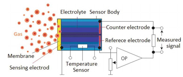
Figure 6: Schematic Electrochemical Sensor Parts
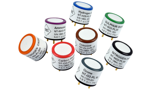
Figure 7: Example of Electrochemical Sensor for Toxic and Flammable Gas Detection
Electrochemical sensors quantify the concentration of gases by oxidizing or reducing the target gas at an electrode and recording the current that this process generates. These devices feature working, counter, and reference electrodes submerged in an electrolyte, all contained within a small housing that includes a gas-permeable membrane. Gases pass through this membrane and participate in a redox reaction at the working electrode, producing a current that is directly proportional to the gas concentration. Known for their exceptional specificity and precision, these sensors can be compromised by the presence of other gases and tend to have a finite operational life due to the gradual depletion of their active materials.
Advantages:
• Fast response time
• Good linear output
• High accuracy
Disadvantages:
• Need oxygen-rich environment
• Consume liquid electrolytes
• Susceptible to temperature, humidity, and pressure changes
Non-Dispersive Infrared (NDIR) Gas Sensor
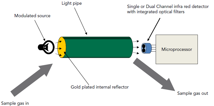
Figure 8: Schematic NDIR Sensor Parts
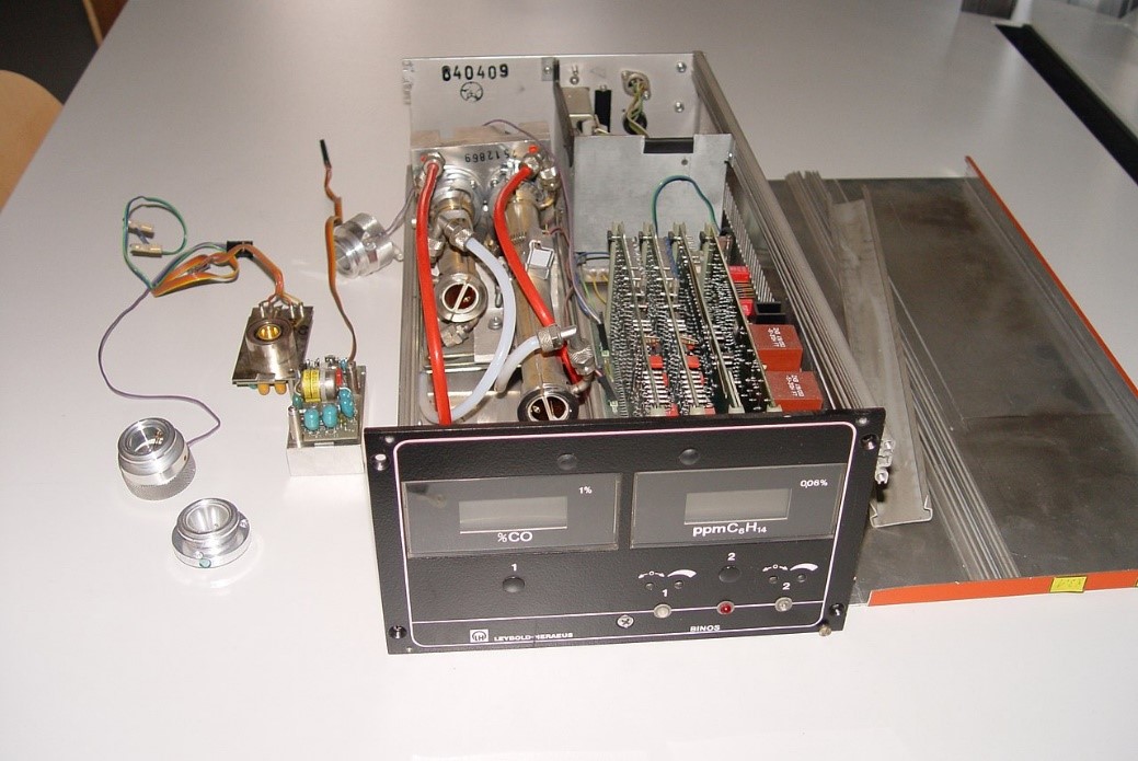
Figure 9: Actual NDIR Sensor
NDIR sensors utilize an infrared light source and detector to determine gas concentrations through infrared absorption. They are equipped with an infrared light source, a chamber for gas samples, a wavelength filter, and an infrared detector. As gases absorb particular wavelengths of infrared light, the sensor's detector quantifies the extent of this absorption to assess the gas concentration. These sensors boast high accuracy and longevity, and are not susceptible to sensor poisoning. However, they tend to be costly and are limited to detecting gases that absorb infrared light.
Advantages:
• Measures gases like CO2
• Does not require oxygen
• High measurement concentration capability
• Good stability and low maintenance costs
Disadvantages:
• High power consumption
• Expensive
• Complex structure and software/hardware requirements
Catalytic Gas Sensor
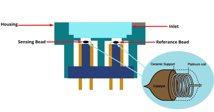
Figure 10: Schematic Catalytic Sensor Parts
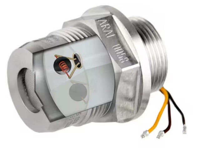
Figure 11: Catalytic Sensor Example
Catalytic sensors identify flammable gases through a catalytic bead that alters its resistance during gas oxidation. These sensors incorporate a catalyst-coated sensing bead alongside a reference element, arranged in a Wheatstone bridge configuration within protective casings. The oxidation of combustible gases on the catalyst surface produces heat, leading to a resistance change detected by the circuit. Effective in rapidly detecting low concentrations of gas, these sensors necessitate the presence of oxygen and may be compromised by specific chemical substances.
Advantages:
• Strong resistance to harsh climates and poisonous gases
• Long service life
• Low maintenance costs
Disadvantages:
• Risk of explosion or fire in dark environments
• Susceptible to poisoning by sulfide and halogen compounds
• Larger errors in low-oxygen environments
Photoionization Detector (PID)
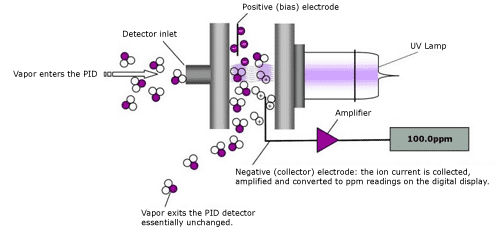
Figure 12: Schematic PID Parts
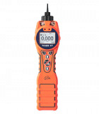
Figure 13: PID Example
Photoionization detectors (PID) utilize ultraviolet light to ionize gases and measure the electrical current produced by these ions to assess gas concentrations. The system comprises a UV lamp, an ionization chamber, and electrodes. The ionization of gas molecules triggers an electrical current across the electrodes, which correlates directly with the concentration of volatile organic compounds (VOCs). PIDs offer high sensitivity to VOCs and rapid detection capabilities, though they are expensive and their performance can be influenced by environmental variables such as humidity and temperature.
Advantages:
• High sensitivity
• No poisoning problem
• Can detect over 400 types of volatile organic gases
Disadvantages:
• High cost of lamp replacement
• Cannot measure air, toxic gases, or natural gas
Thermal Conductivity Gas Sensor
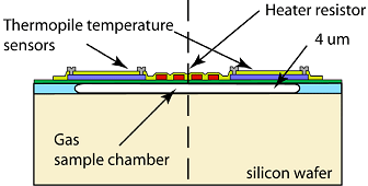
Figure 14: Schematic Thermal Conductivity Sensor Parts
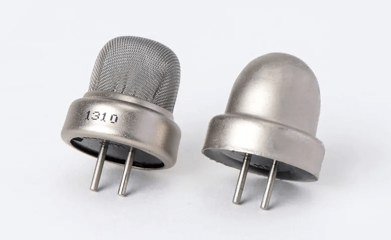
Figure 15: Thermal conductivity Sensor Example
Thermal conductivity sensors evaluate variations in thermal conductivity due to different gases. These sensors usually incorporate two thermal elements, such as thermistors or thermal conductors, arranged in a bridge circuit configuration. One element is exposed to the target gas while the other interfaces with a reference gas. Changes in the gas composition alter the thermal conductivity around the sensor, impacting its temperature and resistance. This change is then quantified by the circuit. These devices are straightforward, robust, and capable of detecting many gases, though they offer less sensitivity and are susceptible to changes in ambient temperature.
Advantages:
•Wide detection range
•Good working stability
•Long service life
•No catalyst aging problems
Disadvantages:
•Poor detection accuracy
•Low sensitivity
•Susceptible to temperature drift
Gas Chromatograph Analyzer
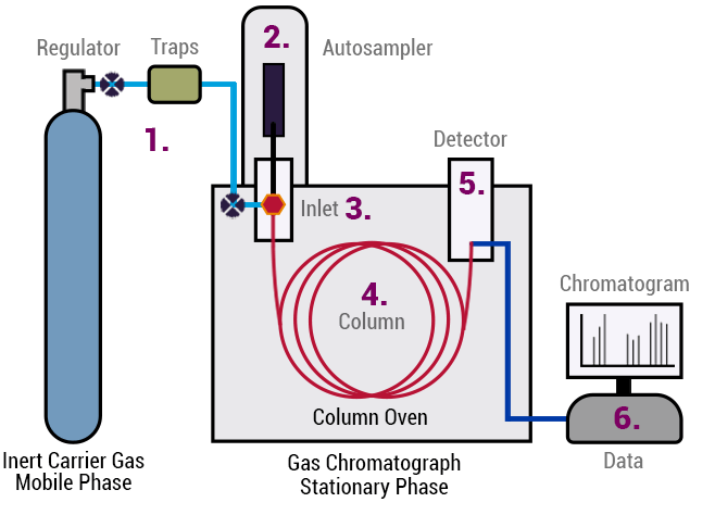
Figure 16: Schematic Gas Chromatograph Analyzer Parts
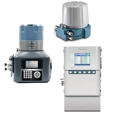
Figure 17: Gas Chromatograph Analyzer Actual
Gas chromatography analyzers distinguish and quantify the components of a gas mixture using diverse detectors. They consist of an injector, a chromatographic column, a carrier gas system, and a detector, all housed within a controlled setting. Gas samples are introduced through the injector to the column, where they are separated according to how they interact with the column's material. The separated components are then detected and measured by the detector. These analyzers offer high precision and can analyze intricate mixtures, yet they are costly, demand expert handling, and are more cumbersome compared to other gas sensors.
Advantages:
•High sensitivity
•Suitable for micro and trace analysis
•Can analyze complex multiphase separation gases
Disadvantages:
•Cannot achieve continuous sampling and analysis
•More suitable for laboratory analysis than industrial field gas monitoring
Capacitance-based Gas Sensor
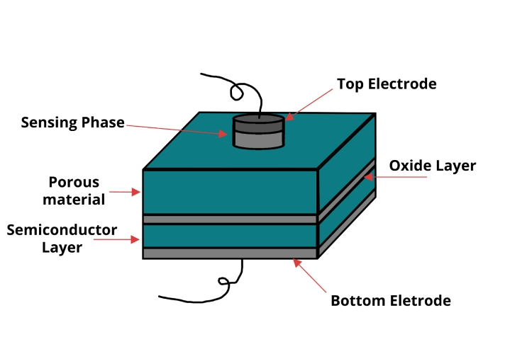
Figure 18: Schematic Capacitance-based Sensor Parts
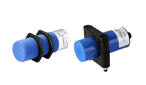
Figure 19: Capacitance-based Sensor Actual
Capacitance sensors identify shifts in capacitance due to alterations in the dielectric constant of a gas absorbed onto the sensor's surface. These sensors are comprised of a capacitor that includes a dielectric material reactive to the target gas, typically designed on a MEMS platform to enhance compactness. The absorption of gas molecules modifies the dielectric constant, resulting in a change in capacitance that is then quantified. While these sensors are exceptionally sensitive and ideal for detecting moisture, they are susceptible to environmental influences such as temperature.
Advantages:
•High sensitivity
•Fast response time, suitable for real-time monitoring
•Low power consumption
Disadvantages:
•Long-term stability issues
•Cross-sensitivity to other gases
•Limited detection ranges
Acoustic-based Gas Sensors
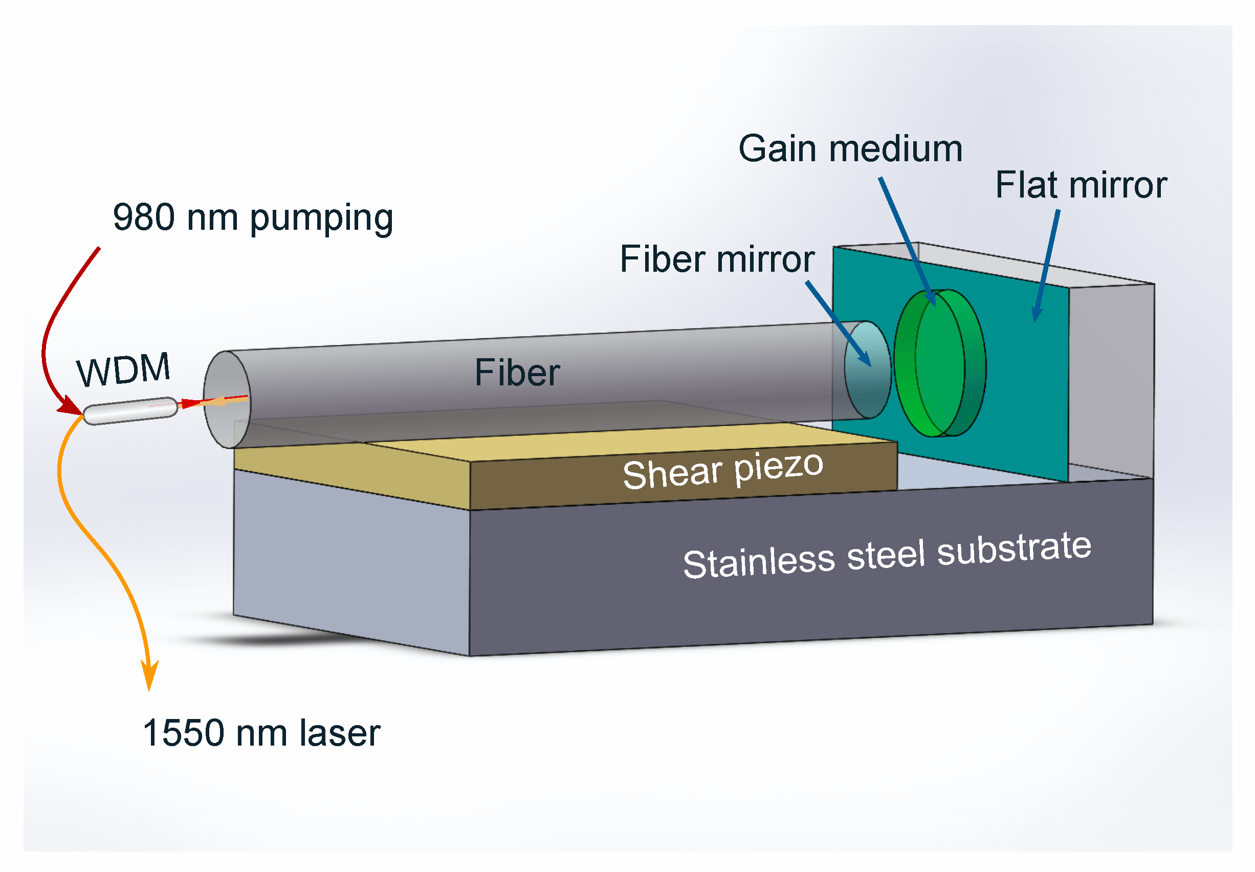
Figure 20: Schematic Acoustic-based Gas Sensor Parts
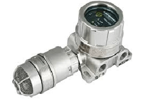
Figure 21: Acoustic-based Gas Sensors Actual
Acoustic sensors operate based on the concept that changes in gas composition affect the speed of sound within the mixture. They are equipped with a sound wave transmitter and receiver, set within a chamber or along a pathway where the gas mixture can interact with the sound waves. The variations in the acoustic properties due to this interaction are recorded and analyzed. These sensors offer non-invasive monitoring and rapid detection of changes, yet they may face challenges with precision and often need regular calibration.
Advantages:
•Detect nerve and blister agents
•Battery-less, suitable for wireless applications
•Usable in harsh and rotating parts
Disadvantages:
•Difficult to handle during fabrication due to small size
Calorimetric Gas Sensor
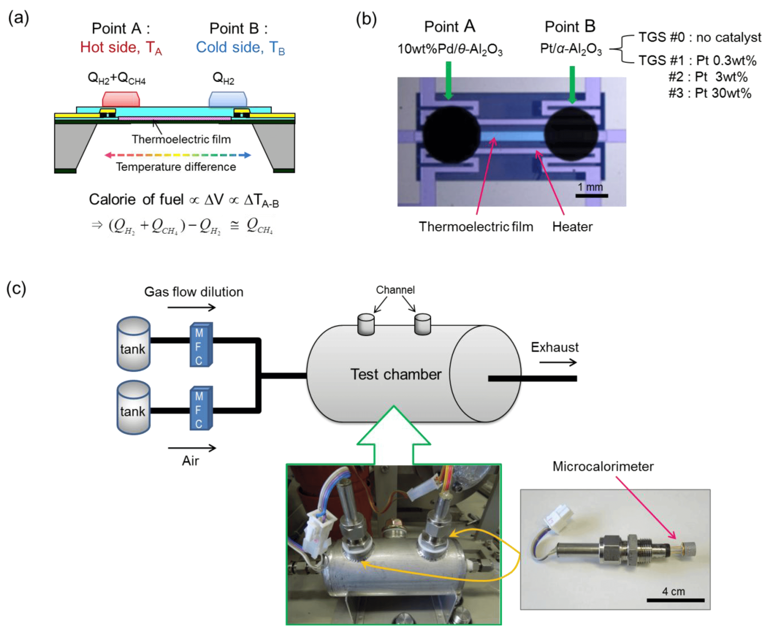
Figure 22: (a) Schematic Illustration of Device Structure and Working Principle, and (b) Photograph of a Calorimetric-TGS Device. (c) Schematic and Photograph of the Measurement System for the Calorimetric-TGS Devices.
Calorimetric sensors detect heat variations resulting from chemical reactions between the target gas and a specific reagent. These devices are equipped with a reaction chamber containing a catalyst or reagent that, upon reacting with the gas, generates heat. This increase or decrease in temperature is then measured by an integrated temperature sensor. While these sensors are particularly effective for detecting certain gases, they tend to exhibit slower reaction times and less sensitivity than other sensor types.
Advantages:
•Fast response time for real-time monitoring
•Simple design
•Long-term stability and reliability
•Low power consumption
Disadvantages:
•Catalysts have a limited lifespan and can degrade
•Slower response times for very low gas concentrations
Magnetic Gas Sensor
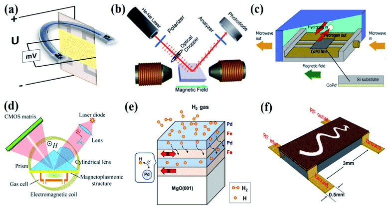
Figure 23: Magnetic Effects Used for the Gas Sensing Device Fabrication. (a) Hall Effect, (b) Kerr Effect. (c) Ferromagnetic Resonance (FMR) Effect. (d) Magneto-Plasmonic Effect. (e) Magnetic Moment or Spin Effect. (f) Magnetostatic Spin-Wave (MSW) Effect.
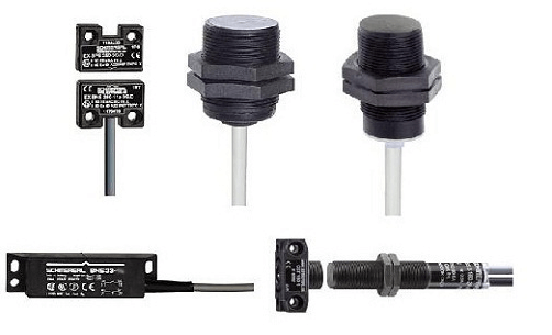
Figure 24: Magnetic Sensor Actual
Magnetic sensors utilize the magnetic characteristics of specific gases, such as oxygen, to determine their concentration. These devices feature magnetic materials that alter their magnetic properties when exposed to certain gases. These changes are detected by a magnetic field sensor integrated within the unit. The modification in the magnetic properties caused by the presence of the target gas is measured and analyzed. Magnetic sensors offer high stability and are largely impervious to interference from other gases. However, they can only detect paramagnetic gases and tend to be more sophisticated and expensive.
Advantages:
•Non-invasive operation
•Rapid detection and real-time monitoring
•Some types do not require external power
Disadvantages:
•Complex and expensive
•Require frequent calibration
•Can only measure gases with specific magnetic properties
•Incapable to external magnetic fields and temperature changes
Components of a Metal Oxide Gas Sensor
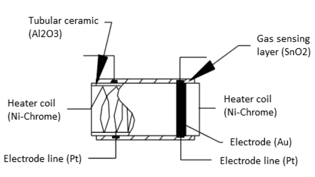
Figure 25: Schematic Components of a Metal Oxide Gas Sensor
Gas Sensing Layer: The gas sensing layer is the sensor's core, detecting gas concentration changes. It acts as a chemiresistor, changing resistance when exposed to specific gases. Usually made of Tin Dioxide (SnO₂), which has excess electrons (donor elements), it alters resistance in the presence of toxic gases. This resistance change affects the current flow, correlating with gas concentration, making the gas sensing layer, for precise gas detection.
Heater Coil: The heater coil boosts the gas sensing layer's sensitivity and efficiency by keeping it at a high temperature. Made from Nickel-Chromium, known for its high melting point, it remains stable under constant heat. This heating activates the gas sensing layer, enabling it to respond better to gases. The heater coil ensures optimal sensor performance by providing thermal energy consistently.
Electrode Line: The electrode line efficiently transmits the small currents from the gas sensing layer. Constructed of Platinum, prized for its conductivity, it ensures accurate current transmission and measurement. This efficient electron movement is good for the sensor's accuracy in gas detection.
Electrode: The electrode connects the gas sensing layer's output to the electrode line. Made of Gold (Au – Aurum), a superior conductor, it ensures minimal resistance and efficient current transmission. This connection is important for precise gas concentration measurements, enabling seamless electrical signal transfer from the sensing element to the output terminals.
Tubular Ceramic: The tubular ceramic, usually made of Aluminum oxide (Al₂O₃), sits between the heater coil and the gas sensing layer. Its high melting point supports the burn-in process of the sensing layer, maintaining high sensitivity and efficient output current. The tubular ceramic offers structural stability and thermal insulation, protecting the sensor's internal parts and enhancing durability and performance.
Mesh Over the Sensing Element: A metal mesh covers the sensing element, shielding sensitive components from dust and corrosive particles. This mesh protects the sensor from external contaminants and maintains the gas sensing layer's integrity and longevity. By filtering harmful particles, the mesh ensures the sensor operates accurately and reliably over long periods.
How Gas Sensors Work?
Basic Technology
Gas sensors use a chemiresistor, typically made from Tin Dioxide (SnO2). SnO2 is an n-type semiconductor that has many free electrons, which are good for conducting electricity.
Function in Clean Air
In clean air, oxygen molecules from the atmosphere attach to the SnO2 surface. These oxygen molecules capture free electrons from the SnO2, creating a barrier that stops current flow. Therefore, the sensor’s output is zero or at a baseline.
Reaction to Toxic or Combustible Gases
When exposed to toxic or combustible gases, these gases react with the oxygen on the SnO2 surface, releasing the trapped electrons. This increase in free electrons raises the conductivity of SnO2. The level of this conductivity change matches the concentration of the gas.
How to Use a Gas Sensor?
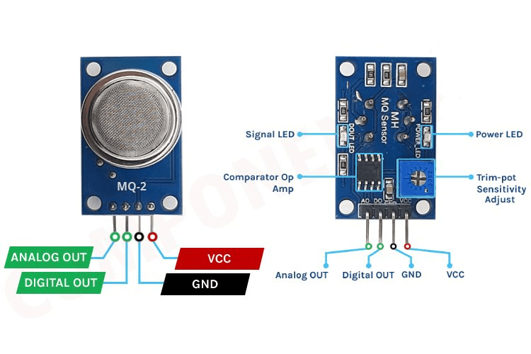
Figure 26: Gas Sensor Module And 4 Terminals
A basic gas sensor has six terminals: four for input/output (labeled A, A, B, B) and two for heating the coil (labeled H, H). The input/output terminals can be used interchangeably. Gas sensors often come as modules that include the sensor itself and a comparator IC. These modules typically have four terminals: Vcc (power supply), GND (ground), Digital output (a signal indicating the presence of gas), and Analog output (a continuous voltage indicating gas concentration).
Increasing Sensor Output
Since the gas sensor alone produces a small output (in millivolts), an external circuit is needed to convert this output into a digital signal. This conversion uses a comparator (commonly an LM393), an adjustable potentiometer, and additional resistors and capacitors. The LM393 comparator takes the sensor's output, compares it with a reference voltage, and provides a digital output. The potentiometer sets the gas concentration level that triggers a high output.
Basic Circuit Diagram of a Gas Sensor Module
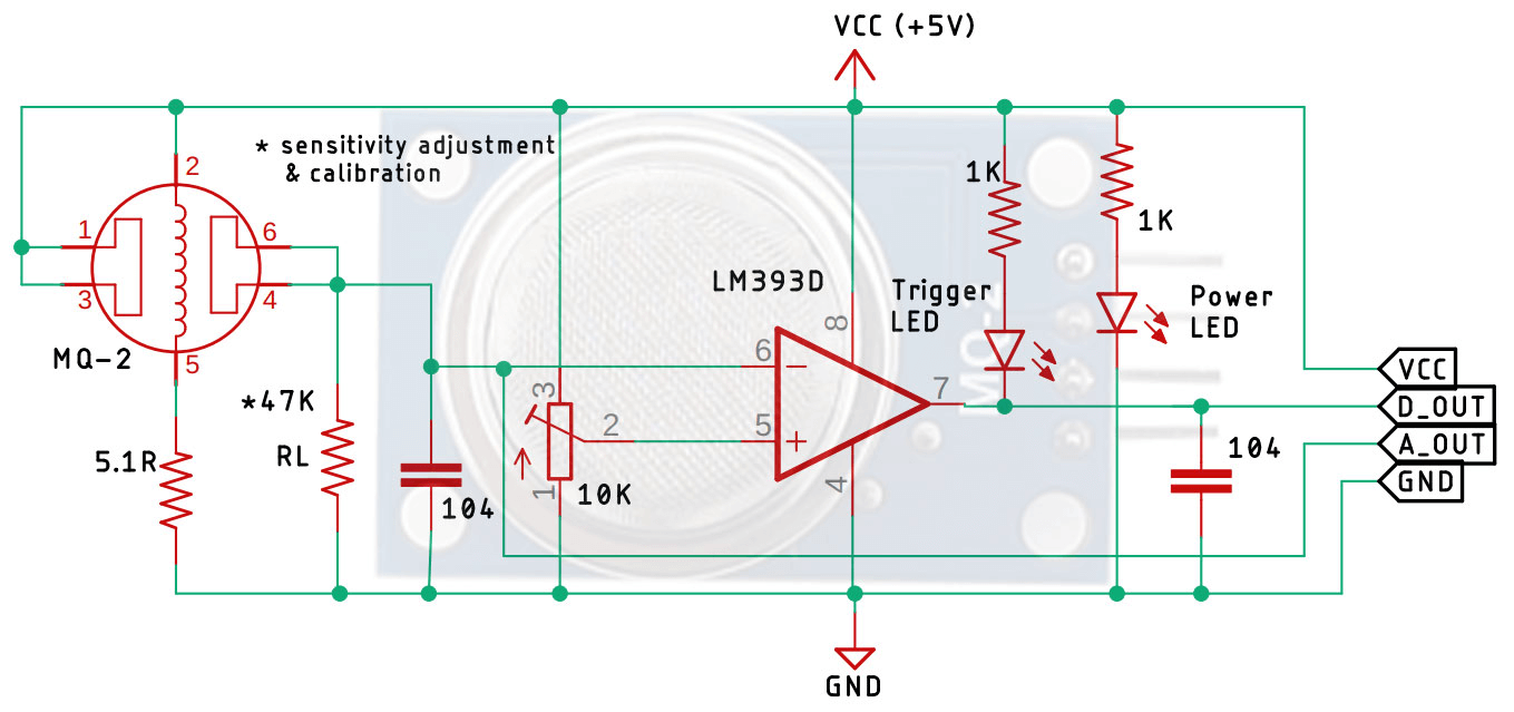
Figure 27: Basic Circuit Diagram of a Gas Sensor in a Gas Sensor Module
The gas sensor circuit includes input/output terminals (A and B) and heater terminals (H). The heater coil must receive sufficient voltage to activate the sensor. Without this input voltage, the output current is negligible. Once powered, the sensing layer can detect gases.
No Gas Present:
The resistance of the sensing layer remains unchanged, resulting in minimal output current.
Gas Present:
The pre-heated coil facilitates detection by changing the material's resistance, altering the current flow at the load resistance (RL).
The value of RL, typically between 10KΩ to 47KΩ, is calibrated based on the desired sensitivity to gas concentration. Lower resistance values reduce sensitivity, while higher resistance values increase sensitivity. The circuit also includes an LM393 op-amp, which converts the analog signal to a digital one. An onboard 10K potentiometer allows adjustment of the sensor module's sensitivity. Two LEDs provide visual indicators: one for power (indicating the board is powered) and one for triggering (indicating the set threshold has been reached). Decoupling capacitors reduce noise, ensuring stable and accurate sensor readings.
Most Popular Gas Sensors
The MQ series of semiconductor gas sensors, including models like the MQ-2, MQ-3, MQ-4, MQ-5, MQ-6, MQ-7, MQ-8, MQ-9, MQ-131, MQ-135, MQ-136, MQ-137, MQ-138, MQ-214, MQ-303A, MQ-306A, and MQ-309A, are well-regarded for their reliability and accuracy in various applications. These sensors meet a wide range of environmental and industrial requirements.
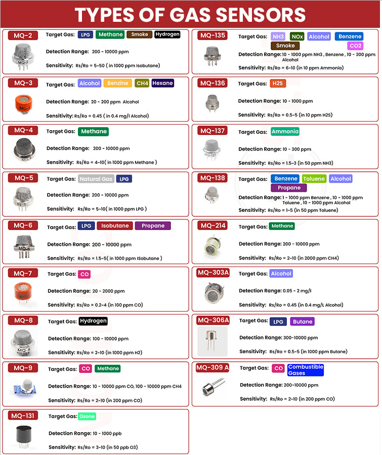
Figure 28: Table of Different Types of Gas Sensor
MQ-2: Detects combustible gases and smoke.
Preheat the sensor for 24 hours. Calibrate with a known concentration of the target gas, such as 1000 ppm of methane. Adjust the load resistance based on the output voltage.
Observe the slow increase in resistance as the internal heater stabilizes. Ensure the sensor has fully warmed up before taking readings to avoid inaccuracies.
MQ-3: Alcohol vapor detection, often used in breathalyzers.
Warm the sensor for at least 48 hours before initial use. Calibrate with 0.4 mg/L alcohol in the air. Adjust the load resistor to match specific application needs.
Monitor sensitivity drift during calibration and adjust intervals based on stability. Record ambient temperature and humidity as they affect accuracy.
MQ-4: Methane and natural gas detection.
Preheat for 24 hours. Calibrate in a controlled environment with 5000 ppm methane. Adjust the load resistor accordingly.
Closely monitor response time. Slow response may indicate issues with the heater or temperature stability in the environment.
MQ-5: LPG, natural gas, and coal gas detection.
Similar to MQ-4 but calibrate for multiple gases using specific concentrations.
Maintain a stable environment during calibration. Temperature fluctuations can cause significant variations in readings.
MQ-6: Detects LPG, butane, isobutane, and propane.
Preheat and calibrate as with MQ-5. Ensure proper ventilation to avoid hazardous gas concentrations during calibration.
Pay attention to the sensor's recovery time after exposure to high gas concentrations. Prolonged exposure can saturate the sensor, requiring a longer recovery period.
MQ-7: Carbon monoxide detection.
Preheat for 48 hours. Calibrate in a 100 ppm CO environment. Adjust the load resistor to match the desired sensitivity.
Observe behavior under fluctuating temperatures as CO sensors are sensitive to temperature changes. Implement a compensation algorithm if needed.
MQ-8: Hydrogen gas detection.
Preheat for 24 hours. Calibrate in a 1000 ppm hydrogen environment. Adjust load resistance for optimal performance.
Ensure the calibration environment is free from other gases and contaminants, as hydrogen sensors are highly sensitive to contamination.
MQ-9: Detects carbon monoxide and flammable gases.
Preheat for 48 hours. Calibrate separately for CO and flammable gases using known concentrations. Adjust load resistors for each gas detection.
Ensure that calibration for one gas does not interfere with sensitivity to the other. Focus on the dual gas detection capability.
MQ-131: Ozone detection.
Preheat for 24 hours. Calibrate in a 0.1 ppm ozone environment. Adjust load resistance accordingly.
Regularly check sensor sensitivity and recalibrate as ozone sensors can degrade over time with exposure to high concentrations.
MQ-135: Air quality sensor detecting NH3, NOx, alcohol, benzene, smoke, and CO2.
Preheat for 24 hours. Use various controlled gas environments to calibrate for each specific gas.
Maintain a detail records of calibration settings for each gas type. Regular recalibration is good to maintain accuracy due to the broad range of detectable gases.
MQ-136 to MQ-309A: Each sensor targets specific gases and has similar calibration as described as MQ-135.
Preheat for 24 hours and use various controlled gas environments to calibrate for each specific gas.
Understand specific sensitivities and cross-sensitivities of each sensor. Regular maintenance, calibration, and environmental control are key for optimal performance.
Applications of Gas Sensor
Industrial Safety: In industrial environments, gas sensors monitor toxic gases like carbon monoxide, methane, and hydrogen sulfide. These sensors are installed in areas prone to leaks, such as chemical plants, manufacturing units, and storage facilities. They operate continuously, sending real-time data to a central control system. When gas levels exceed set thresholds, the system triggers alarms and automatic shutdowns to prevent hazards. Operators routinely calibrate these sensors, performing field checks and zero-span calibrations to ensure accuracy.
Household Safety: At home, gas sensors detect leaks of natural gas or propane, preventing explosions or poisoning. These sensors are often part of smart home systems, alerting homeowners via smartphones or contacting emergency services. They are usually installed in kitchens, basements, or near gas appliances. Homeowners should regularly test these devices and replace batteries as needed to keep them operational.
Oil and Gas Industry: On oil rigs, gas sensors monitor volatile organic compounds (VOCs) and other hazardous gases. These sensors are built to withstand harsh offshore conditions, such as extreme temperatures and humidity. They are part of a larger safety system that includes ventilation controls and emergency shutdown mechanisms. Daily inspections ensure sensors are free from contaminants and functioning correctly, with on-site adjustments made using portable calibration devices.
Hospitality Industry: In hotels, gas sensors enforce no-smoking policies by detecting cigarette smoke and triggering ventilation systems or alarms. Discreetly installed in guest rooms and common areas, these sensors help hotel management promptly address violations and maintain a smoke-free environment. Regular maintenance checks clean sensors and verify their sensitivity to smoke particles.
Office Environments: In office buildings, gas sensors monitor indoor air quality, focusing on pollutants like carbon dioxide, VOCs, and particulate matter. Integrated with HVAC systems, these sensors regulate air flow to ensure a healthy workspace. Facility managers analyze sensor data to optimize ventilation, reducing energy costs while maintaining air quality. Periodic calibration and software updates are performed to enhance sensor performance.
Air Conditioning Systems: Gas sensors in air conditioners manage CO2 levels, improving indoor air quality. Part of an automated system, they adjust ventilation rates based on real-time CO2 concentrations. Technicians check sensor functionality during routine maintenance to ensure accurate readings and optimal air quality.
Fire Detection Systems: Gas sensors in fire detection systems identify smoke and toxic gases like carbon monoxide early. They provide warnings, enabling timely evacuation and fire control measures. Fire safety personnel regularly test these systems by simulating smoke conditions to ensure sensor responsiveness and reliability.
Mining Operations: In mining, gas sensors detect dangerous gases like methane and carbon monoxide, for worker safety. These sensors are part of a networked safety system, providing continuous monitoring and automatic ventilation adjustments. Miners also carry portable gas detectors as an additional safety measure. Regular training on sensor uses and emergency response procedures ensures preparedness.
Breath Analyzers: Gas sensors in breath analyzers measure blood alcohol content (BAC) by detecting ethanol in breath. Used by law enforcement and individuals for monitoring, these devices require calibration with known ethanol standards to maintain accuracy. Users follow strict protocols, such as ensuring the device is at the correct temperature and avoiding contamination, to secure reliable results.
Conclusion
As technology progresses, gas sensors are becoming more powerful and wide, enhancing their performance and making them required in many areas, including industrial safety and household security. Understanding how gas sensors work and how to maintain them highlights their technical importance and their significant contribution to protecting lives and improving the quality of our surroundings. Whether in factories, homes, or public spaces, gas sensors are key to a safer, healthier future. As technology progresses, gas sensors are becoming more advance and well developed, enhancing their performance and making them indispensable in many areas, including industrial safety and household security.
Frequently Asked Questions [FAQ]
1. What is the Gas Sensors?
A gas sensor is a device that detects the presence and concentration of gases in the air. It converts chemical information from the gas into an electronic signal that can be measured and analyzed.
2. What is the purpose of a gas sensor?
The primary purpose of a gas sensor is to monitor and detect gas leaks or the presence of hazardous gases. It helps ensure safety by providing early warnings of dangerous gas levels, preventing accidents, and ensuring compliance with safety regulations.
3. What are the advantages of gas sensor?
Gas sensors are devices that detect and measure gas concentrations in the air, ensuring safety by providing early warnings of hazardous gases. They are accurate, offering precise measurements, and enhance safety in various environments through early detection. Gas sensors can be integrated into automated systems for continuous monitoring, reducing the need for manual inspections and lowering labor costs. Their versatility allows them to detect a wide range of gases, making them suitable for numerous applications, from industrial plants and environmental monitoring to residential safety and medical settings. An example is a carbon monoxide sensor in homes that alerts occupants to dangerous levels of CO gas.
4. Where are gas sensors used?
Gas sensors are widely used across various industries and settings, including monitoring gases in manufacturing plants, refineries, and chemical plants to ensure industrial safety. Measuring air quality and detecting pollution levels for environmental protection. Detecting carbon monoxide and natural gas leaks in homes for residential safety. Monitoring respiratory gases in healthcare setting. And detecting gas emissions in vehicles to ensure compliance with environmental standards.
5. What is an example of a gas sensor?
A common example of a gas sensor is the carbon monoxide (CO) sensor used in homes. This sensor detects CO gas, which is colorless and odorless, providing an alarm when dangerous levels are present to prevent poisoning.
6. How to work a gas sensor?
A gas sensor works by being exposed to a target gas, which interacts with the sensor's detection material, causing a chemical reaction that changes the sensor’s properties. This change is converted into an electronic signal, which is then processed and measured to provide a readable output, such as a numerical value or an alarm. For example, a carbon monoxide sensor in a home continuously monitors the air. If CO gas is detected, it reacts with the sensor, creating an electronic signal that triggers an alarm if the CO levels are too high, warning you of the danger.
About us
ALLELCO LIMITED
Read more
Quick inquiry
Please send an inquiry, we will respond immediately.
Driving Motion: A Comprehensive Guide to Actuators
on May 28th
Stepper Motor Wire Guide - Color Codes, Wiring Methods
on May 23th
Popular Posts
-

What is GND in the circuit?
on January 1th 2946
-

RJ-45 Connector Guide: RJ-45 Connector Color Codes, Wiring Schemes, R-J45 Applications, RJ-45 Datasheets
on January 1th 2502
-

Fiber Connector Types: SC Vs LC And LC Vs MTP
on January 1th 2091
-

Understanding Power Supply Voltages in Electronics VCC, VDD, VEE, VSS, and GND
on November 9th 1898
-

Comparison Between DB9 and RS232
on January 1th 1765
-

What Is An LR44 Battery?
Electricity, that ubiquitous force, quietly permeates every aspect of our daily lives, from trivial gadgets to life-threatening medical equipment, it plays a silent role. However, truly grasping this energy, especially how to store and efficiently output it, is no easy task. It is against this background that this article will focus on a type of coin cell battery that may seem insignificant on the...on January 1th 1714
-

Understanding the Fundamentals:Inductance Resistance, andCapacitance
In the intricate dance of electrical engineering, a trio of fundamental elements takes center stage: inductance, resistance, and capacitance. Each bears unique traits that dictate the dynamic rhythms of electronic circuits. Here, we embark on a journey to decipher the complexities of these components, to uncover their distinct roles and practical uses within the vast electrical orchestra. Inductan...on January 1th 1662
-

CR2430 Battery Comprehensive Guide: Specifications, Applications and Comparison to CR2032 Batteries
What is CR2430 battery ?Benefits of CR2430 BatteriesNormCR2430 Battery ApplicationsCR2430 EquivalentCR2430 VS CR2032Battery CR2430 SizeWhat to look for when buying the CR2430 and equivalentsData Sheet PDFFrequently Asked Questions Batteries are the heart of small electronic devices. Among the many types available, coin cells play a crucial role, commonly found in calculators, remote controls, and ...on January 1th 1567
-

What Is RF and Why Do We Use It?
Radio Frequency (RF) technology is a key part of modern wireless communication, enabling data transmission over long distances without physical connections. This article delves into the basics of RF, explaining how electromagnetic radiation (EMR) makes RF communication possible. We will explore the principles of EMR, the creation and control of RF signals, and their wide-ranging uses. The article ...on January 1th 1550
-

CR2450 vs CR2032: Can The Battery Be Used Instead?
Lithium manganese batteries do have some similarities with other lithium batteries. High energy density and long service life are the characteristics they have in common. This kind of battery has won the trust and favor of many consumers because of its unique safety. Expensive tech gadgets? Small appliances in our homes? Look around and you'll see them everywhere. Among these many lithium-manganes...on January 1th 1519
