Comprehensive Guide to the ATmega328P AVR Microcontroller
The ATmega328P is a widely used microcontroller, with its pinout referring to the layout and function description of the microcontroller's pins. The significance of the ATmega328P pinout lies in its specification of the microcontroller's input/output interfaces, power, and ground pins, serving as a crucial basis for circuit design and programming. This article will explore the relevant knowledge of the ATmega328P, including pin configuration, functional characteristics, specifications, application areas, and the differences between the ATmega328P and ATmega328PU.Catalog
ATmega328P Microcontroller
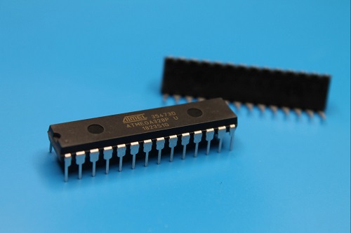
The ATmega328P is a low-power CMOS 8-bit microcontroller based on the enhanced AVR RISC architecture, featuring many pins and functions. Developed by Atmel Corporation (now part of Microchip Technology), it utilizes 8-bit CMOS technology and RISC CPU design, enhancing its performance and power efficiency with features like automatic sleep and an internal temperature sensor.
The ATmega328P chip offers internal protection and various programming methods, allowing the prioritization of this controller under different circumstances. This IC enables modern communication methods with other modules and the microcontroller itself. Thanks to these details, the usage of the ATmega328P microcontroller is rapidly increasing daily.
Pin Configuration
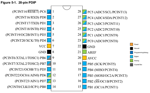
The ATMEGA328P chip has 28 general-purpose input/output (GPIO) pins, with each pin's usage and pin diagram configuration detailed in the following diagram.
ATmega328P Features
High performance, low power AVR 8-bit microcontroller:
- Advanced RISC architecture;
- High endurance non-volatile memory segments;
- Power-on reset and programmable brown-out detection;
- Internal calibrated oscillator;
- External and internal interrupt sources;
- Six sleep modes: Idle, ADC Noise Reduction, Power-save, Power-down, Standby, and Extended Standby.
ATmega328P Specifications
- Flash Memory: 32K
- SRAM: 2KB
- EEPROM Memory: 1KB
- CPU Speed: 20MHZ
- Interface Type: I2C, SPI, USART
- Power Supply Voltage Min: 1.8V Max: 5.5V
- Power Supply for Surface Mount Devices: Surface mount
- Package Type: PDIP/TQFP
- Pin Count: 28-PDIP, 32-TQFP
- Operating Temperature Range: -40°C to +85°C
- Input/Output Lines: 23
- Number of ADC Inputs: 8
- 8-bit Timer/Counter: 2
- 16-bit Timer/Counter: 1
- PWM: 6
- Programming Modes: ISP, IAP, H/PV
- Simulation Mode: debugWIRE
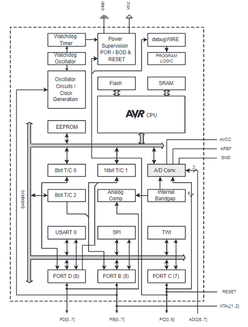
Functional Diagram
Application Areas
Most embedded systems, such as those based on embedded systems technology, use the ATmega328 for performing various operations due to its extensive examples and help material available online.
It is utilized in Arduino, making it one of the most popular controllers.
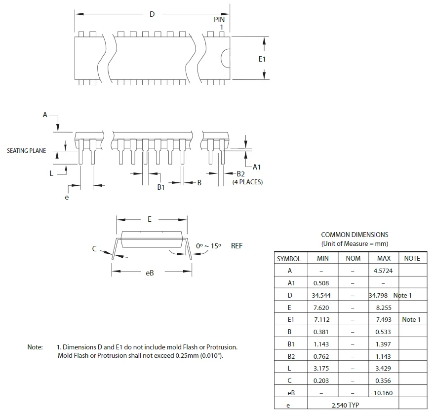
Design Schematic
How to Use the ATmega328P
Using the ATMEGA328P is similar to any other controller, fundamentally centered around programming. Initially, the controller is programmed by writing the relevant program files to its flash memory. Once this code is dumped, the controller executes this code and provides appropriate responses.
The entire process of using the ATMEGA328 includes:
Listing the functions the controller is to perform.
Writing these functions in a programming language within an Integrated Development Environment (IDE) program.
ATMEGA328P programming can also be done in the ARDUINO IDE.
After writing the program, the next stage involves compiling the code to identify and correct errors.
Have the IDE generate a hex file for the written program after compiling.
This hex file contains the machine code that should be written in the controller's flash memory.
Choose a programming device to establish communication between the PC and ATMEGA328P (usually an SPI programmer made for AVR controllers). You can also use the ARDUINO UNO board for ATMEGA328P programming.
Run the programmer software and select the appropriate hex file.
Use this program to burn the hex file into the ATMEGA328P flash memory.
Disconnect the programmer, connect the controller's relevant peripherals, and then power up the system.
Differences Between ATmega328, ATmega328P, and ATmega328PU
For ordinary users, it's hard to understand why there are different markings on the crystals and which one to choose. Let's try to clarify:
The difference between the first two crystal models is minimal in traditional application scenarios, making them essentially interchangeable.
Compared to the Atmega328, the ATmega328P significantly reduces power consumption, as reflected in the technical specifications. Therefore, the ATmega328P adopted a more refined technology process in the early stages of development. This usually means that these chips are more expensive. The low-power AVR microcontrollers classified with PicoPower technology make the ATmega328P more suitable for battery-powered devices, where energy consumption control measures are necessary.
The chip signatures of different options vary, and when reading them with programs like Avrdude, you may encounter error messages for atmega328p if the microcontroller type is specified incorrectly.
Only the Atmega328P supports the TQFP32 package, while the TQFP328 package is incompatible, related to the crystal size. For the latter, crystal thickness is a limiting factor.
The Atmega328 lacks a low-power detector fuse that can further reduce power consumption and disable BOD (Brown-Out Detect). This fuse exists in the second model, a feature only visible in the PicoPower series versions ending with 48PA, 88PA, 168PA, 328P, etc., and also applies to BODS, and BODSE fuses.
There are subtle differences in the command system involving navigation instructions, although, in this respect, chips of both variants can run compiled programs.
The letters "PU" represent the crystal's package type, i.e., a DIP28 plastic package. The ATmega328 is easily installed in such packaging, thus the addition of this suffix. Moreover, other package variants are indicated by letter combinations like AU, MU, etc.
The Arduino based on the atmega328p mini is a simplified choice as it omits the USB to serial part. The atmega328p pro mini is commonly known to be a form of the atmega328p au. However, for some devices, this size may be too small, and the PU model is more appropriate.
Microcontrollers are widely used in various devices, including the atmega328p test transistor and the atmega328p nano 3.0 controller.
1ATmega328P Alternatives
ATMEGA8535, ATMEGA16, ATMEGA32,
Frequently Asked Questions [FAQ]
1. What is the AVR architecture of ATmega328P?
Instructions in the program memory are executed with a single-level pipelining. While one instruction is executed, the next instruction is pre-fetched from the program memory. This concept enables instructions to be executed in every clock cycle.
2. What is the disadvantage of ATmega328P?
A major con for commercial use is that it is single source, proprietary architecture. Pros : These can be such as ATmega328 is a versatile chip. It has Adc, I2c,pwm support,40 pin ic,etc. Cons: atmega328 is expensive when considering small tasks.
3. Is ATmega328P analog or digital?
The Atmel ATmega328P microcontroller used on the Arduino Uno has an analog-to-digital conversion (ADC) module capable of converting an analog voltage into a 10-bit number from 0 to 1023 or an 8-bit number from 0 to 255. The input to the module can be selected to come from any one of six inputs on the chip.
4. Does ATmega328P have eeprom?
The supported micro-controllers on the various Arduino and Genuino boards have different amounts of EEPROM: 1024 bytes on the ATmega328P, 512 bytes on the ATmega168 and ATmega8, 4 KB (4096 bytes) on the ATmega1280 and ATmega2560. The Arduino and Genuino 101 boards have an emulated EEPROM space of 1024 bytes.
About us
ALLELCO LIMITED
Read more
Quick inquiry
Please send an inquiry, we will respond immediately.
Comprehensive Understanding of the 78M05 Chip
on March 22th
The Function and Working Principle of BTN8982TA
on March 15th
Popular Posts
-

What is GND in the circuit?
on January 1th 3271
-

RJ-45 Connector Guide: RJ-45 Connector Color Codes, Wiring Schemes, R-J45 Applications, RJ-45 Datasheets
on January 1th 2815
-

Understanding Power Supply Voltages in Electronics VCC, VDD, VEE, VSS, and GND
on November 20th 2635
-

Fiber Connector Types: SC Vs LC And LC Vs MTP
on January 1th 2265
-

Comparison Between DB9 and RS232
on January 1th 1881
-

What Is An LR44 Battery?
Electricity, that ubiquitous force, quietly permeates every aspect of our daily lives, from trivial gadgets to life-threatening medical equipment, it plays a silent role. However, truly grasping this energy, especially how to store and efficiently output it, is no easy task. It is against this background that this article will focus on a type of coin cell battery that may seem insignificant on the...on January 1th 1846
-

Understanding the Fundamentals:Inductance Resistance, andCapacitance
In the intricate dance of electrical engineering, a trio of fundamental elements takes center stage: inductance, resistance, and capacitance. Each bears unique traits that dictate the dynamic rhythms of electronic circuits. Here, we embark on a journey to decipher the complexities of these components, to uncover their distinct roles and practical uses within the vast electrical orchestra. Inductan...on January 1th 1806
-

What Is RF and Why Do We Use It?
Radio Frequency (RF) technology is a key part of modern wireless communication, enabling data transmission over long distances without physical connections. This article delves into the basics of RF, explaining how electromagnetic radiation (EMR) makes RF communication possible. We will explore the principles of EMR, the creation and control of RF signals, and their wide-ranging uses. The article ...on January 1th 1800
-

CR2430 Battery Comprehensive Guide: Specifications, Applications and Comparison to CR2032 Batteries
What is CR2430 battery ?Benefits of CR2430 BatteriesNormCR2430 Battery ApplicationsCR2430 EquivalentCR2430 VS CR2032Battery CR2430 SizeWhat to look for when buying the CR2430 and equivalentsData Sheet PDFFrequently Asked Questions Batteries are the heart of small electronic devices. Among the many types available, coin cells play a crucial role, commonly found in calculators, remote controls, and ...on January 1th 1797
-
Comprehensive guide to hFE in transistors
Transistors are crucial components in modern electronic devices, enabling signal amplification and control. This article delves into the knowledge surrounding hFE, including how to select a transistor's hFE value, how to find hFE, and the gain of different types of transistors. Through our exploration of hFE, we gain a deeper understanding of how transistors work and their role in electronic circu...on November 20th 1782
