Achieving Peak Performance with the Maximum Power Transfer Theorem
The principle of the Maximum Power Transfer Theorem is a foundation in electrical engineering, underpinning efficient circuit design and optimal power delivery across diverse applications from industrial to consumer electronics. This theorem theorizes that for a source with a finite internal resistance, maximum power is delivered to the load when the load resistance is exactly equal to the source's internal resistance. This article digs into a multifaceted exploration of this theorem, examining its theoretical underpinnings through the lens of Thevenin's theorem and its practical implications in various applications, ranging from DC circuits to complex AC systems. By dissecting the mathematical formulation and employing calculus to derive conditions for maximum power transfer, the article not only clarifies the theoretical aspects but also bridges the gap to real-world applications. It scrutinizes the trade-offs between maximum power transfer and efficiency, especially pertinent in energy-sensitive applications, and extends the discussion to the strategic use of impedance matching in enhancing system performance in audio systems, power electronics, and telecommunications.
Catalog
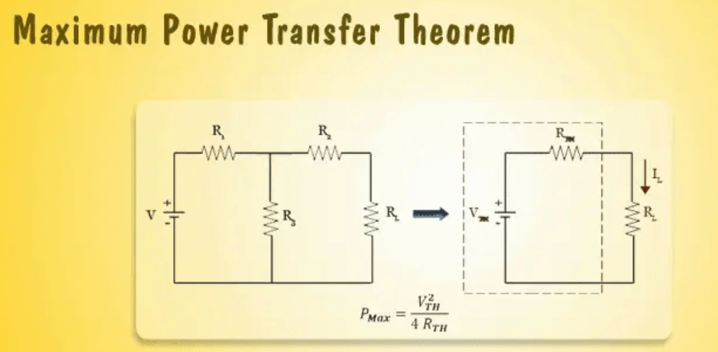
Figure 1: Maximum Power Transfer Theorem
Values of the Maximum Power Transfer Theorem
The Maximum Power Transfer Theorem is key in DC circuit design and power optimization. It states that to maximize power transfer from a source to a load, the load resistance must equal the source's internal resistance. This condition ensures optimal power delivery.
Using Thevenin's theorem, a DC power supply system can be modeled as a voltage source in series with a resistor. This model simplifies power transfer calculations. According to Ohm's law, power P is given by P = I2R where I is current and R is resistance. The power delivered to the load is maximized when the load resistance RL matches the source resistance RS. At this point, the voltage across the load is half the source voltage, optimizing the power delivered.
Achieving maximum power transfer involves fine-tuning the load resistance to match the source's internal resistance. This is done through iterative adjustments and measurements. For example, a circuit diagram with Thevenin’s equivalent and a load resistor can illustrate the impact of resistance adjustments on power transfer efficiency.
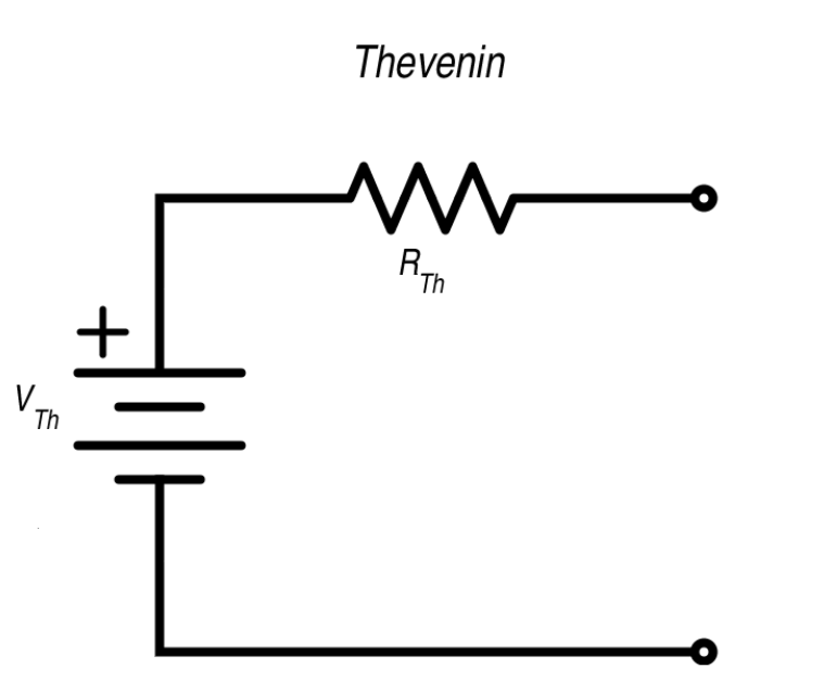
Figure 2: Illustrative Example of Maximum Power Transfer
Example of Maximum Power Transfer
To understand the practical application of the Maximum Power Transfer Theorem, let's examine a Thevenin equivalent circuit. Set the Thevenin resistance at 0.8 ohms. For optimal power transfer, the load resistance should also be 0.8 ohms. Under these conditions, the circuit achieves a power output of approximately 39.2 watts.
Now, consider what happens when you change the load resistance. If you adjust it to 0.5 ohms or 1.1 ohms, the power dissipation changes significantly. At 0.5 ohms, the circuit sees an increase in current but lower efficiency due to a higher voltage drop across the internal resistance. At 1.1 ohms, the current flow decreases, leading to lower power dissipation. This demonstrates that power output is maximized only when the load resistance matches the source resistance.
The theorem is not just theoretical; it is dynamic in designing efficient power systems. For example, in radio transmitter design, matching the transmitter's output impedance with the antenna's impedance maximizes signal strength and range. In solar power systems, grid-tied inverters must match the inverter's output impedance with the grid's impedance to optimize power transfer, enhancing the efficiency and reliability of solar installations.
Understanding the Trade-off: Maximum Power vs. Maximum Efficiency
The Maximum Power Transfer Theorem distinguishes between maximizing power transfer and achieving maximum efficiency, particularly in AC power systems. In AC power distribution, the goal is to enhance efficiency, which requires a lower generator impedance compared to the load impedance. This approach is different from the theorem's guideline, which advises matching impedances for optimal power transfer.

Figure 3: Audio Systems
In high-fidelity audio systems, it is significant to maintain a low output impedance on amplifiers relative to a higher speaker load impedance. This setup minimizes power loss and preserves sound quality, showcasing a deviation from the theorem's recommendation for maximum power transfer.

Figure 4: RF Amplifiers
For RF amplifiers, where low noise is risky, engineers often use impedance mismatching. This strategy reduces noise interference, contrary to the theorem's suggestions. The Maximum Power Transfer Theorem focuses on maximizing power output but does not consider efficiency or noise, which are more needed in these scenarios.
Unveiling the Formula for Maximum Power Transfer
The foundation of the Maximum Power Transfer Theorem is a simple mathematical expression that connects the output power across a load (PL) to the DC source characteristics and the load's resistance (RL) The formula is:

Here, VTH is the Thevenin equivalent voltage, and RTh is the Thevenin equivalent resistance of the source. This formula is required for identifying the optimal conditions for power transfer.
To find the conditions for maximum power transfer, we use calculus. By setting the derivative of the power equation  to zero, we see that maximum power transfer happens when the load resistance RL equals the Thevenin resistance RTh . This ensures that the voltage across the load is half of the source voltage, leading to the most efficient power delivery in the given circuit configuration.
This theoretical framework is key in both academic studies and practical applications. It provides a clear guideline for engineers designing circuits where efficient power transfer is a must.
Detailed Proof and Analysis of the Maximum Power Transfer Theorem
Proving the Maximum Power Transfer Theorem is the ultimate example of using calculus in electrical engineering. The process starts by converting any circuit into its Thevenin equivalent. This simplifies the circuit to a single voltage source(VTh) and a series resistance (RTh).
The theorem states that the power dissipated across the load resistor (RL) is maximized under specific conditions. We begin by setting up the power dissipation formula:

To determine the condition for maximum power, we take the derivative of PL concerning RL and set it to zero:

By solving this equation through differentiation and algebraic simplification, we find that RL = RTh is the point of maximum power transfer. This means the load resistance that maximizes power transfer is equal to the Thevenin resistance of the source. Further verification, such as second derivative tests or plotting the function, confirms that at RL = RTh power dissipation reaches its peak.
Evaluating Efficiency in Maximum Power Transfer Scenarios
The Maximum Power Transfer Theorem helps optimize power transfer, but its efficiency is limited to 50%. This efficiency comes from the ratio of the power delivered to the load to the total power output by the source. When the load resistance (RL)equals the Thevenin resistance RTh both resistances consume equal power, splitting the source power equally between the load and the internal resistance.
To calculate this, consider the total power supplied by the source:

When RL = RTh , the power across RL is:

Thus, the efficiency  as the ratio of the power across the load to the total power, is:

This reveals a significant trade-off in system design. Optimizing for maximum power transfer often means sacrificing efficiency.

Figure 5: Impedance Matching in Amplifier Circuits
Optimizing Impedance Matching for Superior Power Transfer
Impedance matching, a technique from the Maximum Power Transfer Theorem, is settling in the output stages of amplifier circuits. This process involves adjusting the impedance of loudspeakers to match the amplifier's output impedance using matching transformers. This alignment optimizes the amplifier's ability to transfer maximum power to the loudspeakers, enhancing overall sound power output. By matching impedance, the amplifier operates at its most efficient power transfer conditions. This maximizes audio output and preserves sound fidelity by minimizing losses that occur when impedances are mismatched. These losses often appear as heat or reflected power, which can degrade performance and potentially damage the amplifier or speakers.
In practice, implementing impedance matching involves selecting transformers that can handle the amplifier's power rating and provide the correct transformation ratio to match the speaker's impedance. This ensures that the energy from the amplifier is efficiently converted into sound energy rather than wasted. Consequently, the quality and volume of the audio output are enhanced.
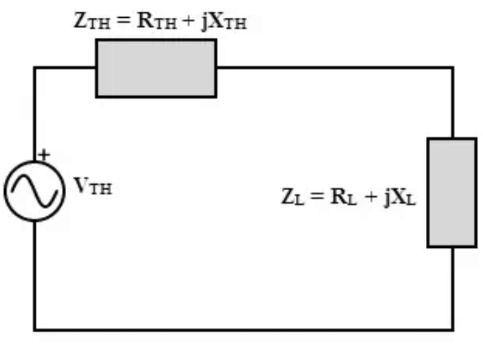
Figure 6: Maximum Power Transfer Theorem for DC and AC Circuits
Applying the Maximum Power Transfer Theorem in AC and DC Circuits
The Maximum Power Transfer Theorem is an ultimate principle in electrical engineering that applies to both DC and AC circuits, though its implementation varies between the two.
For DC circuits, the theorem states that maximum power transfer occurs when the load resistance is equal to the source resistance. This alignment is serious for designing efficient power systems and is particularly significant in battery-operated devices and solar power systems. For instance, in solar panel systems, power optimizers adjust the load's effective resistance to match the solar cells' optimal output resistance, thereby maximizing energy transfer and enhancing system efficiency. This approach not only improves efficiency but also extends the lifespan of the energy source by minimizing power losses.
In AC circuits, the application of the theorem is more complex due to the presence of phase angles and reactive components. Maximum power transfer in AC circuits occurs when the load impedance is the complex conjugate of the source impedance. This involves aligning the load's reactive component to be equal and opposite to that of the source, effectively canceling out reactive elements and aligning phase angles. This principle is used in systems where phase distortion can severely affect performance, such as RF transmitters and audio amplifiers. Resistive and reactive components must be carefully calculated and balanced before use, typically capacitors and inductors, to adjust the phase, thereby maximizing power efficiency and improving the quality and reliability of the system.
Applications of the Maximum Power Transfer Theorem
The Maximum Power Transfer Theorem plays a serious role in enhancing efficiency and performance across various technologies, particularly in electronic devices, solar panel systems, and sound systems where optimal impedance matching is needed.

Figure 7: Electronic Devices
In electronic devices, the theorem ensures that power amplifiers deliver maximum power to the load. For instance, in wireless communication systems, engineers carefully match the impedance of the transmitter to that of the antenna to minimize power loss and maximize signal efficiency. During practical operations, engineers use network analyzers to measure and adjust impedance, fine-tuning components like inductors and capacitors to achieve the desired match. These adjustments significantly impact overall performance, highlighting the theorem's importance in real-world applications.

Figure 8: Solar Panel Systems
In solar panel systems, the Maximum Power Transfer Theorem optimizes energy conversion. The power output of a solar panel depends on the load impedance presented by the inverter or charge controller. Engineers use Maximum Power Point Tracking (MPPT) algorithms to dynamically adjust the load impedance to match the panel's internal impedance, ensuring maximum power extraction under varying sunlight conditions. This involves continuous monitoring and real-time adjustments, requiring sophisticated software algorithms and data analysis. By accounting for subtle variations in sunlight and temperature, this process is both complex and key for maximizing efficiency.

Figure 9: Sound Systems
In sound systems, proper impedance matching is dynamic for high-quality audio output. Audio engineers use the theorem to match the impedance of speakers with amplifiers, ensuring maximum power transfer and minimizing distortion for clear sound. During setup, engineers employ tools like impedance bridges and audio analyzers to fine-tune the system. This precise matching often involves adjusting crossover networks and selecting appropriate speaker cables, demonstrating the importance of detail in achieving superior sound quality.
Implications of the Maximum Power Transfer Theorem
The Maximum Power Transfer Theorem offers notable benefits, such as enhanced power delivery and reduced component stress, leading to safer and more efficient circuit designs. However, it also has limitations, including a 50% efficiency cap and inapplicability to non-linear systems.
The theorem ensures that the load receives maximum power from the source when the load impedance matches the source impedance. Practically, this involves engineers using impedance-matching techniques during circuit design. To illustrate, in RF circuit design, network analyzers and impedance bridges measure and adjust the impedance of various components, ensuring optimal power delivery. This precise matching minimizes power loss, settling in high-frequency applications where even small mismatches can lead to significant inefficiencies.
By ensuring maximum power transfer, the theorem reduces stress on components. Matching impedances balances current and voltage levels, preventing excessive heat and potential damage to circuit elements. Engineers use thermal imaging and current probes to monitor component performance under load. Adjustments to heat sinks and cooling systems are often required to maintain optimal conditions, enhancing circuit longevity and reliability.
Reduced component stress contributes to safer circuit designs. In power electronics, proper impedance matching prevents overheating and electrical failures. Engineers conduct detailed simulations and stress tests to ensure components operate within safe limits. This involves modeling the thermal and electrical behavior of the circuit using software tools, followed by physical testing to validate the models. This iterative process ensures the final design is both efficient and safe.
Despite its advantages, the theorem has limitations. A major limitation is the 50% efficiency cap, meaning only half of the power supplied by the source reaches the load, while the other half is dissipated in the source impedance. This is particularly relevant in battery-powered and energy-harvesting applications, where efficiency is unsafe. Engineers must balance the need for maximum power transfer with overall efficiency requirements, often opting for designs that deviate slightly from the theorem to achieve higher efficiency.
The theorem does not apply to non-linear systems, where the relationship between voltage and current is not proportional. In practical scenarios, such as switching power supplies and digital circuits, non-linear components like transistors and diodes are common. Engineers use alternative techniques, such as load-line analysis and small-signal modeling, to optimize power transfer in these systems. These methods involve detailed characterization of the non-linear behavior of components and specialized simulation tools to predict and enhance performance.
Solving Network Problems Using the Maximum Power Transfer Theorem
Implementing the Maximum Power Transfer Theorem in network analysis involves a systematic approach. This includes identifying the load resistance, calculating the Thevenin resistance and voltage, and applying the theorem to determine optimal power transfer conditions.
First, identify the load resistance (Rload) in the circuit. This involves examining the circuit schematic and using tools like ohmmeters or impedance analyzers to measure the load component's resistance. Accurate measurement is key, as even minor inaccuracies can affect the overall analysis. Engineers must calibrate measurement tools and consider the temperature coefficient of resistive materials for precision.
Next, calculate the Thevenin equivalent resistance RTh and voltage VTh:
Open-Circuit Voltage (VTh ): Measure or calculate the voltage across the load terminals with the load removed. Use a high-impedance voltmeter to avoid loading the circuit and distorting the measurement.
Thevenin Resistance (RTh ): Determine the equivalent resistance seen from the load terminals with all independent voltage sources replaced by short circuits and independent current sources by open circuits. Engineers often use simulation software like SPICE to model the circuit and accurately compute the Thevenin resistance. Consider parasitic elements and component tolerances during this stage.
With RTh and VTh determined, apply the theorem to ensure maximum power transfer by matching the load resistance to the Thevenin resistance:
Adjust the load resistance to match RTh. This might involve selecting a load resistor with the closest possible value or using a variable resistor (potentiometer) for fine-tuning. Monitor the power delivered to the load using power meters and thermal sensors to ensure safe and optimal operation.
After initial adjustments, verify the performance. Use oscilloscopes and spectrum analyzers to check voltage, current, and power waveforms. Fine-tuning may be required to account for real-world non-idealities, such as contact resistance and temperature variations.

Figure 10: Transmission Line Considerations
Transmission Line Performance with the Maximum Power Transfer Theorem
In systems involving transmission lines (such as coaxial cables and twisted pair cables), accurate impedance matching at the source and load ends is beneficial to maintain signal integrity and prevent signal reflections, which can cause interference, signal attenuation, standing waves, and power loss. Engineers employ Time Domain Reflectometry (TDR) to measure and visualize these reflections by injecting a test signal and analyzing the reflected signals to identify mismatches and make needed adjustments.
Characterizing the Transmission Line
Use a network analyzer to measure the characteristic impedance of the transmission line. This tool sends a range of frequencies through the line and measures the reflected signals to determine the impedance.
Calibrate the network analyzer using known standards to ensure accurate measurements, compensating for any inherent errors in the measurement system.
Matching the Source Impedance: Adjust the source impedance to match the transmission line's characteristic impedance. This may involve adding matching networks, such as series or parallel resistors, capacitors, or inductors. Use an oscilloscope to verify the source signal integrity. Look for a clean waveform without distortions, indicating minimal reflections.
Matching the Load Impedance: Adjust the load impedance to match the transmission line's characteristic impedance. This might involve fine-tuning the load using variable components or designing custom impedance-matching networks. Measure the signal at the load end using an oscilloscope and network analyzer to ensure the waveform remains undistorted, confirming successful impedance matching.
High-Speed and Analog Signal Contexts: In high-speed digital circuits and analog signal applications, the seriousness of impedance matching escalates with higher frequencies, where issues like crosstalk, electromagnetic interference (EMI), and attenuation become more pronounced. Engineers tackle these challenges through meticulous design and testing, ensuring that transmission lines are routed with controlled impedance using PCB design software equipped with integrated impedance calculators for designing traces with the correct width and spacing. They implement proper grounding and shielding techniques, such as ground planes, shielding enclosures, and differential signaling, to minimize EMI. In addition, engineers design filters to mitigate unwanted frequencies and noise using filter design software and circuit simulators and implement signal conditioning circuits like amplifiers and attenuators to maintain signal quality over long distances. Fine-tuning these circuits ensures they match the impedance and frequency characteristics of the transmission line.
Subtle Operational Considerations: Temperature effects can cause transmission line characteristics to vary, necessitating the use of temperature-compensating materials and designs to maintain consistent impedance matching. Furthermore, real-world components have tolerances that can affect impedance matching; thus, selecting high-precision components and performing tolerance analysis during the design phase is needed to mitigate these issues. In systems experiencing dynamic load conditions, implementing adaptive impedance matching techniques, such as electronically tunable matching networks, is key to maintaining optimal performance.
Conclusion
The Maximum Power Transfer Theorem serves as a needed framework for optimizing power delivery in electrical circuits, balancing the intricacies of theoretical electrical principles with the practical demands of modern engineering applications. While it provides a method to maximize power output, it also introduces a risky consideration of efficiency, particularly relevant in today’s energy-conscious environment. The detailed examination of the theorem’s applications—from solar panel systems to sophisticated audio setups—underscores its versatility and useful role in enhancing the performance and reliability of technological systems. Nevertheless, the inherent efficiency cap and its limited applicability to non-linear systems prompt a nuanced application, encouraging engineers to sometimes deviate from the theorem to prioritize overall system efficiency over mere power maximization. Thus, this theorem not only enriches our understanding of electrical circuit behavior but also guides engineering decisions in a landscape where power efficiency and system optimization are dominant.
Frequently Asked Questions [FAQ]
1. What is the maximum power transfer theorem and Norton's theorem?
Maximum Power Transfer Theorem: This principle states that to obtain maximum external power from a source with a finite internal resistance, the resistance of the load must equal the resistance of the source.
Norton’s Theorem: This theorem simplifies a network into a single current source and parallel resistance. It states that any two-terminal linear circuit can be replaced by an equivalent circuit consisting of a Norton current source in parallel with a Norton resistance.
2. What is the maximum power transfer theorem complex?
When referred to as "complex," this usually means applying the theorem in circuits where the components, including sources and loads, have complex impedance rather than purely resistive elements. The condition for maximum power transfer in this context is that the load impedance should be the complex conjugate of the source impedance.
3. What is the maximum power principle?
This is another term often used interchangeably with the Maximum Power Transfer Theorem. It refers to the guideline for optimizing the power output by adjusting the load to match the source’s internal resistance or impedance.
4. What are the steps in the maximum power transfer theorem?
Identify the Source Resistance: Determine the internal resistance of the source or the Thevenin resistance seen from the load.
Calculate or Adjust Load Resistance: Set the load resistance equal to the source's internal resistance.
Verify or Apply: In practical scenarios, this might involve adjusting a variable resistor or calculating the expected load to ensure it matches the source resistance for maximum efficiency.
5. What is the advantage of the maximum power transfer theorem?
The primary advantage is its ability to optimize the efficiency of power delivery from a source to a load, particularly useful in communications (like maximizing signal strength across an antenna) and other electronic applications where power efficiency is serious. However, this often comes at the cost of increased energy loss in the source itself, which might not always be desirable in power-sensitive applications.
About us
ALLELCO LIMITED
Read more
Quick inquiry
Please send an inquiry, we will respond immediately.

What Is RF and Why Do We Use It?
on June 20th

Static Electricity
on June 19th
Popular Posts
-

What is GND in the circuit?
on January 1th 2937
-

RJ-45 Connector Guide: RJ-45 Connector Color Codes, Wiring Schemes, R-J45 Applications, RJ-45 Datasheets
on January 1th 2499
-

Fiber Connector Types: SC Vs LC And LC Vs MTP
on January 1th 2089
-

Understanding Power Supply Voltages in Electronics VCC, VDD, VEE, VSS, and GND
on November 9th 1888
-

Comparison Between DB9 and RS232
on January 1th 1761
-

What Is An LR44 Battery?
Electricity, that ubiquitous force, quietly permeates every aspect of our daily lives, from trivial gadgets to life-threatening medical equipment, it plays a silent role. However, truly grasping this energy, especially how to store and efficiently output it, is no easy task. It is against this background that this article will focus on a type of coin cell battery that may seem insignificant on the...on January 1th 1712
-

Understanding the Fundamentals:Inductance Resistance, andCapacitance
In the intricate dance of electrical engineering, a trio of fundamental elements takes center stage: inductance, resistance, and capacitance. Each bears unique traits that dictate the dynamic rhythms of electronic circuits. Here, we embark on a journey to decipher the complexities of these components, to uncover their distinct roles and practical uses within the vast electrical orchestra. Inductan...on January 1th 1652
-

CR2430 Battery Comprehensive Guide: Specifications, Applications and Comparison to CR2032 Batteries
What is CR2430 battery ?Benefits of CR2430 BatteriesNormCR2430 Battery ApplicationsCR2430 EquivalentCR2430 VS CR2032Battery CR2430 SizeWhat to look for when buying the CR2430 and equivalentsData Sheet PDFFrequently Asked Questions Batteries are the heart of small electronic devices. Among the many types available, coin cells play a crucial role, commonly found in calculators, remote controls, and ...on January 1th 1548
-
What Is RF and Why Do We Use It?
Radio Frequency (RF) technology is a key part of modern wireless communication, enabling data transmission over long distances without physical connections. This article delves into the basics of RF, explaining how electromagnetic radiation (EMR) makes RF communication possible. We will explore the principles of EMR, the creation and control of RF signals, and their wide-ranging uses. The article ...on January 1th 1537
-

CR2450 vs CR2032: Can The Battery Be Used Instead?
Lithium manganese batteries do have some similarities with other lithium batteries. High energy density and long service life are the characteristics they have in common. This kind of battery has won the trust and favor of many consumers because of its unique safety. Expensive tech gadgets? Small appliances in our homes? Look around and you'll see them everywhere. Among these many lithium-manganes...on January 1th 1507
HOT Part Number
-

BZV55C12
Microchip Technology
DIODE ZENER
TFA9887UK/N1,023
NXP Semiconductors
AUDIO AMPLIFIER, 1 FUNC, PBGA29
TLC1541IFN
Texas Instruments
IC ADC 10BIT SAR 20PLCC
NSV50350ADT4G
onsemi
IC CURRENT REGULATOR 10% DPAK
FCPF22N60NT
onsemi
MOSFET N-CH 600V 22A TO220F
LT1009CD
Texas Instruments
IC VREF SHUNT 0.4% 8SOIC
VI-J3Y-EW
Vicor Corporation
DC DC CONVERTER 3.3V 66W
BUK9614-60E118
NXP USA Inc.
NOW NEXPERIA BUK9614-60E - POWER
FDB4020P
onsemi
MOSFET P-CH 20V 16A TO263AB
MCC95-08IO1B
IXYS
MOD THYRISTOR DUAL 800V TO-240AA
EMB2T2R
Rohm Semiconductor
TRANS 2PNP PREBIAS 0.15W EMT6
S25FL128SAGMFI010
Infineon Technologies
IC FLASH 128MBIT SPI/QUAD 16SOIC
M-FIAM9H22
Vicor Corporation
FILTER MILITARY COTS 28 VIN
SN65HVS881PWP
Texas Instruments
IC SERIALIZER 1MBPS 28HTSSOP
HYC9088AR-LF
Microchip Technology
IC TXRX ARCNET COAX 20SIP
MSP430G2210ID
Texas Instruments
IC MCU 16BIT 2KB FLASH 8SOIC
HMC1021Z-RC
Honeywell Aerospace
SENSOR MR WHEAT BRIDGE 8PIN
LB1909MC-BH
onsemi
IC MTR DRV BIPOLR 2.5-16V 10SOIC -

74LCX646MSA
Fairchild Semiconductor
IC TXRX NON-INVERT 3.6V 24SSOP
TCAN1051GVDQ1
Texas Instruments
IC TRANSCEIVER HALF 1/1 8SOIC
FQD3N40TM
onsemi
MOSFET N-CH 400V 2A DPAK
SN75ALS170ADW
Texas Instruments
IC TRANSCEIVER HALF 3/3 20SOIC
0603YA270K4T2A
KYOCERA AVX
CAP CER 27PF 16V NP0 0603
ATMEGA169V-8AU
Atmel
IC MCU 8BIT 16KB FLASH 64TQFP
P6SMB200AHE3/52
Vishay General Semiconductor - Diodes Division
TVS DIODE 171VWM 274VC DO214AA
MMBZ5237BLT1H
onsemi
DIODE ZENER 8.2V .225W SOT23
PCI2050GHK
Texas Instruments
IC INTERFACE SPECIALIZED 209BGA
AD8604ARUZ
Analog Devices Inc.
IC CMOS 4 CIRCUIT 14TSSOP
MPC8313VRAFF
NXP USA Inc.
IC MPU MPC83XX 333MHZ 516BGA
LSM115JE3/TR13
Microchip Technology
DIODE SCHOTTKY 15V 1A DO214BA
STM6321RWY6F
STMicroelectronics
IC SUPERVISOR 1 CHANNEL SOT23-5
74F37PC
onsemi
IC GATE NAND 4CH 2-INP 14DIP
LM2576S-12/NOPB
Texas Instruments
IC REG BUCK 12V 3A TO263-5
L6225N
STMicroelectronics
IC MTR DRV BIPLR 8-52V 20-PWRDIP
MC10EPT20DTR2
onsemi
IC TRANSLATOR UNIDIR 8TSSOP
MAX6126BASA50+
Analog Devices Inc./Maxim Integrated
IC VREF SERIES 0.06% 8SOIC -

PMV30XN,215
NXP USA Inc.
MOSFET N-CH 20V 3.2A TO236AB
KSZ8091RNBCA
Microchip Technology
IC TRANSCEIVER FULL 1/1 32QFN
MSP430FE4252IPMR
Texas Instruments
IC MCU 16BIT 16KB FLASH 64LQFP
MSP430FR5739IRHAR
Texas Instruments
IC MCU 16BIT 16KB FRAM 40VQFN
74F240PC
onsemi
IC BUFFER INVERT 5.5V 20DIP
BUK9875-100A/CUX
NXP USA Inc.
7A, 100V, 0.084OHM, N-CHANNEL MO
AT27BV020-90TC
Microchip Technology
IC EPROM 2MBIT PARALLEL 32TSOP
TRF250-120
Littelfuse Inc.
PTC RESET FUSE 60V 120MA RADIAL
ADP1871ACPZ-0.6-R7
Analog Devices Inc.
IC REG CTRLR BUCK 10LFCSP
OP193FS-REEL
Analog Devices Inc.
IC OPAMP GP 1 CIRCUIT 8SOIC
LTC2376CMS-20#TRPBF
Analog Devices Inc.
IC ADC 20BIT SAR 16MSOP
CY7C131E-55JXC
Infineon Technologies
IC SRAM 8KBIT PARALLEL 52PLCC
GRM188R71H473KA61J
Murata Electronics
CAP CER 0.047UF 50V X7R 0603
LMX2324TM
Texas Instruments
IC PLL FREQ SYNTH 16TSSOP
UCC2813QDR-3Q1
Texas Instruments
IC REG CTRLR MULT TOPOLOGY 8SOIC
1812JC470JAT1A
KYOCERA AVX
CAP CER 47PF 4KV X7R 1812
2SD1207S-AE
Sanyo
TRANS NPN 50V 2A 3MP
CD40192BCN
onsemi
IC DECADE COUNTER 4-BIT 16DIP