74LS76 Dual JK Flip-Flop
The 74LS76 Dual JK Flip-Flop is a small but widely used electronic component in digital circuits. It's often used in systems that need to manage on/off states and timing. This chip contains two JK flip-flops, which are circuits that can hold and control a single bit of data ( a 0 or a 1). In this guide, we'll take a detailed look at how the 74LS76 works, its pin layout, and how it's used in different types of electronics, such as counters and memory units. By the end, you'll have a clear understanding of how this chip fits into various digital projects and how it helps control the flow of data.Catalog
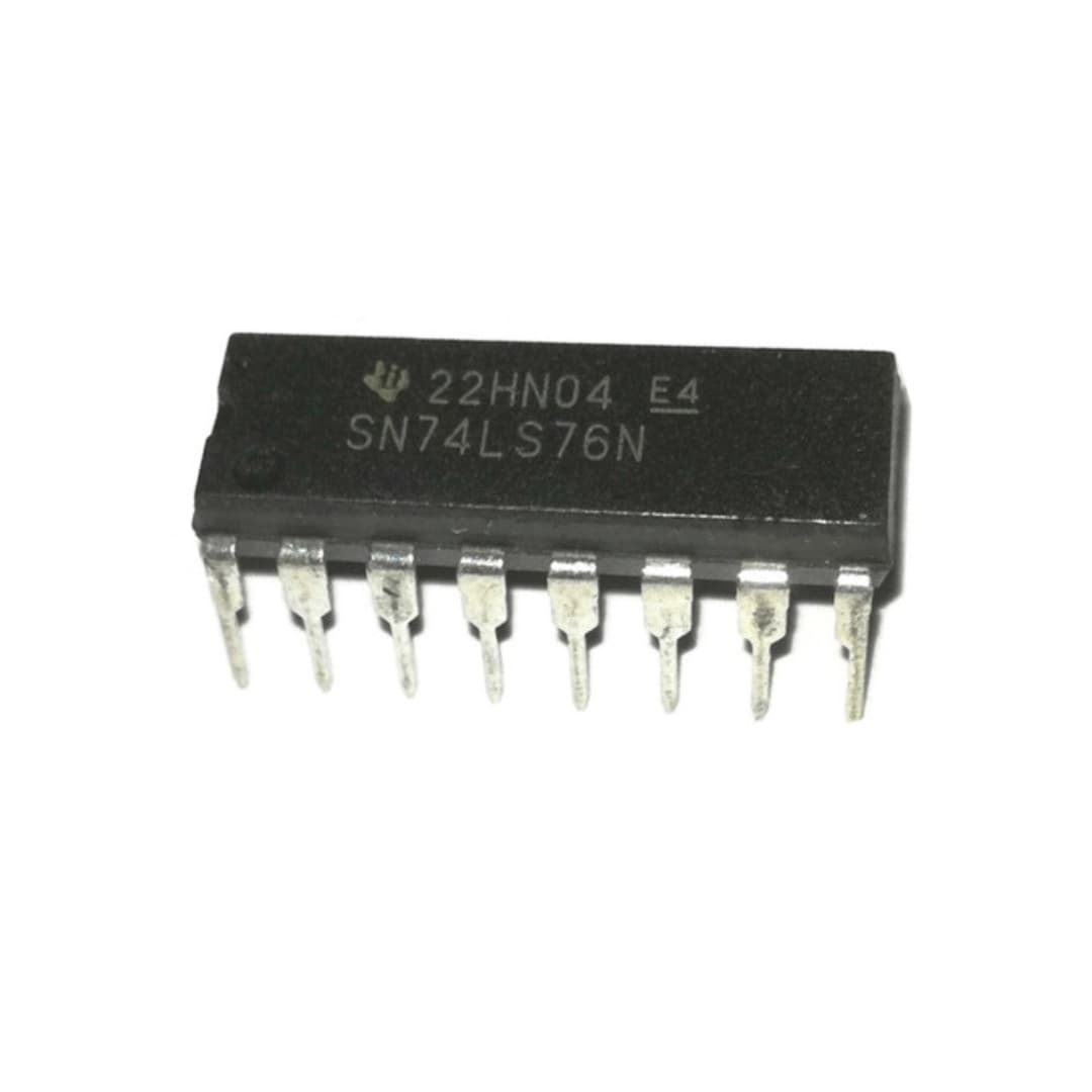
Figure 1: 74LS76 Dual JK Flip-Flop Chip
What Is the 74LS76?
The 74LS76 is a small electronic chip that contains two JK flip-flops. A flip-flop is a type of digital circuit that can switch between two states, which means it can store one bit of data (either a 0 or a 1). Flip-flops are useful in many digital systems because they help control and remember information. The 74LS76 is often used in systems where it's important to manage binary (on/off) states, especially when timing is controlled by a clock signal.
Inputs and Outputs
Each of the two JK flip-flops in the 74LS76 has several inputs (signals you give it) that control how it works: J, K, Clock Pulse (CP), Direct Set (S), and Direct Clear (R). These inputs allow the chip to handle many different tasks in digital systems.
J and K Inputs - These inputs decide what the flip-flop will do when it gets a clock signal. The J input makes the flip-flop "set," which means it will turn on (or go to 1). The K input makes it "reset," meaning it will turn off (or go to 0). If both J and K are on (1), the flip-flop will switch to the opposite state — if it was on, it will turn off, and if it was off, it will turn on.
Clock Input (CP) - The clock input controls when the flip-flop looks at the J and K inputs and decides whether to change its state. In the 74LS76, the flip-flop can change its state when the clock signal either goes up (from low to high) or goes down (from high to low), depending on how it’s set up. This makes the chip good for working with timing in digital systems.
Direct Set (S), and Direct Clear (R) - These inputs allow the flip-flop to directly set its output without waiting for the clock. The preset (S) input makes the flip-flop immediately turn on (1), while the clear (R) input makes it turn off (0). These controls are helpful for quickly resetting or starting up the system without needing the clock signal to trigger the changes.
Pin Configuration of 74LS76
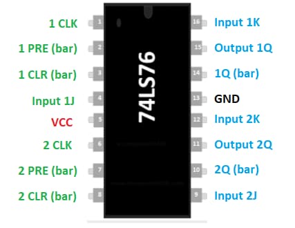
Figure 2: Pin Configuration of 74LS76
The 74LS76 is a popular integrated circuit that contains two JK flip-flops, each with specific pins to control its operations. Below is a simple explanation of what each of the 16 pins on this chip does.
• Pin 1 (1 CLK): This pin is the clock input for the first flip-flop. When the signal connected to this pin changes from HIGH to LOW, it triggers a change in the flip-flop’s state.
• Pin 2 (1 PRE'): This is the preset pin for the first flip-flop. If this pin is activated (set LOW), it forces the flip-flop’s output to become HIGH.
• Pin 3 (1 CLR'): This is the clear pin for the first flip-flop. When this pin is activated (set LOW), it resets the output of the flip-flop, making it LOW.
• Pin 4 (1J): This is the J input for the first flip-flop. It works with the K input (Pin 16) to determine how the flip-flop behaves during the clock cycle.
• Pin 5 (Vcc): This is where the power supply is connected. Typically, the chip requires a 5-volt supply to work properly.
• Pin 6 (2 CLK): This pin is the clock input for the second flip-flop, working in the same way as Pin 1 does for the first flip-flop. A signal going from HIGH to LOW triggers a state change in the second flip-flop.
• Pin 7 (2 PRE'): This pin sets the output of the second flip-flop to HIGH when activated (set LOW).
• Pin 8 (2 CLR'): This is the clear pin for the second flip-flop. When it is activated (set LOW), it resets the output to LOW.
• Pin 9 (2J): The J input for the second flip-flop. Like the J input for the first flip-flop, this works together with the K input to control the flip-flop’s behavior during the clock cycle.
• Pin 10 (2Q'): This is the inverted (opposite) output of the second flip-flop. It gives the opposite value of the regular output.
• Pin 11 (2Q): This is the regular output of the second flip-flop. It changes state based on the clock signal and the values of the J and K inputs.
• Pin 12 (2 K): This is the K input for the second flip-flop. Along with the J input (Pin 9), it determines what happens to the flip-flop during the clock cycle.
• Pin 13 (GND): This pin connects to ground, which provides the reference voltage for the circuit.
• Pin 14 (1Q'): This is the inverted (opposite) output for the first flip-flop. It provides the opposite value of the regular output.
• Pin 15 (1Q): This is the regular output for the first flip-flop. It changes based on the clock signal and the J and K inputs.
• Pin 16 (1k): This is the K input for the first flip-flop, working with the J input (Pin 4) to control the flip-flop's behavior during the clock cycle.
Features and Specifications of the 74LS76
The 74LS76 is a popular integrated circuit (IC) used in many digital systems because it combines speed and low power consumption. It's part of the 74LS family, which is known for its reliable performance in logic-based circuits. Let's take a closer look at some of the main features and specifications of the 74LS76, and why it works well in different types of circuits.
Operating Voltage
The 74LS76 works well with a voltage range of 2 volts to 6 volts. This range gives it the ability to function in various systems, especially those that operate on low or medium power. Many digital systems, including microcontrollers and other similar circuits, use voltages within this range, so the 74LS76 can fit into those systems easily.
Input Voltage Levels
There are two important voltage points that help the 74LS76 decide if a signal is HIGH or LOW:
Minimum High-Level Input Voltage: For the 74LS76 to read a signal as HIGH, the voltage must be at least 2 volts. This means the IC will only recognize a HIGH signal if the voltage is at this level or higher, ensuring it reads signals correctly even if there are slight changes in voltage.
Maximum Low-Level Input Voltage: If the voltage is 0.8 volts or less, the 74LS76 reads the signal as LOW. This helps the IC tell the difference between a LOW and HIGH signal even if the system has small voltage differences.
These voltage levels make sure the 74LS76 can properly understand the signals it receives, which is helpful in circuits where the input voltages might vary slightly. It makes the IC reliable for handling digital signals and working with other parts of the system.
Operating Temperature Range
The 74LS76 can work in a wide range of temperatures, from as cold as -55°C to as hot as 125°C. This allows it to be used in systems that may be exposed to extreme heat or cold, such as outdoor equipment or machines that generate a lot of heat. No matter the temperature, the 74LS76 can keep working without problems, making it a good choice for tough environments where temperature changes are common.
Package Types
The 74LS76 comes in different packaging options, including PDIP (Plastic Dual In-line Package), GDIP (Glass Dual In-line Package), and PDSO (Plastic Small Outline). These different packages make the 74LS76 flexible for various uses. PDIP is easy to handle and often used in early stages of building a circuit since it fits well with breadboards. PDSO, on the other hand, is more compact and is used in smaller devices where space is limited. Because of these packaging options, the 74LS76 can be used in many different types of electronic projects and designs.
How Does the 74LS76 JK Flip-Flop Work?
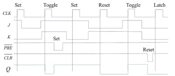
Figure 3: JK Flip-Flop Timing
The 74LS76 contains two separate JK flip-flops, and each one operates based on its input signals. The output of the flip-flop, labeled as Q, is controlled by the combination of J, K, and the clock signal. The JK flip-flop can remember its current state or change it depending on the inputs. Let's take a closer look at how it works.
JK Flip-Flop Functionality
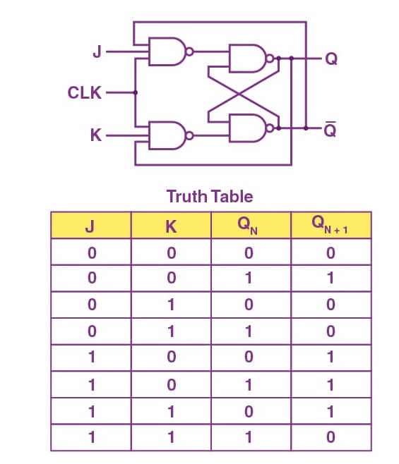
Figure 4: JK Flip-Flop Truth Table
The JK flip-flop changes its output based on the values of J and K at the moment when a clock pulse happens. The clock signal acts like a trigger. Here's what happens with different combinations of J and K:
When J = 0 and K = 0: The output stays the same. In other words, Q doesn't change, and it holds the value it already had before the clock pulse.
When J = 0 and K = 1: The output becomes LOW, meaning Q is set to 0. This is called a "reset," where the flip-flop forces the output to 0.
When J = 1 and K = 0: The output becomes HIGH, meaning Q is set to 1. This is called a "set," where the flip-flop forces the output to 1.
When J = 1 and K = 1: The output switches to the opposite state. This means if Q was 1 before, it will become 0, and if it was 0, it will become 1. This process is called toggling, and it's especially useful in creating counters.
Example: 3-Bit Counter Design
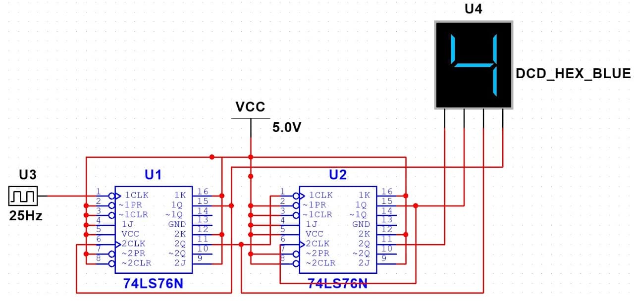
Figure 5: 3-Bit Counter Using 74LS76
One common use of the 74LS76 JK flip-flop is in making counters. In a 3-bit counter, three JK flip-flops are connected one after another, and each flip-flop represents one bit of a binary number.
In this setup, the first flip-flop toggles every time the clock pulse happens. The second flip-flop changes its state whenever the first flip-flop switches from HIGH to LOW. The third flip-flop changes when the second one switches, and so on. This way, the three flip-flops count from 000 to 111 in binary, which represents the numbers 0 to 7 in decimal.
To make sure the flip-flops change states at the right times, an AND gate is often added. This gate helps control the timing of when the flip-flops change, ensuring the counting process runs smoothly. Once the flip-flops generate the binary output, it can be displayed. For example, a BCD-to-7-segment decoder like the 74LS48 can convert the binary number into a format that can be shown on a 7-segment display.
Applications of 74LS76
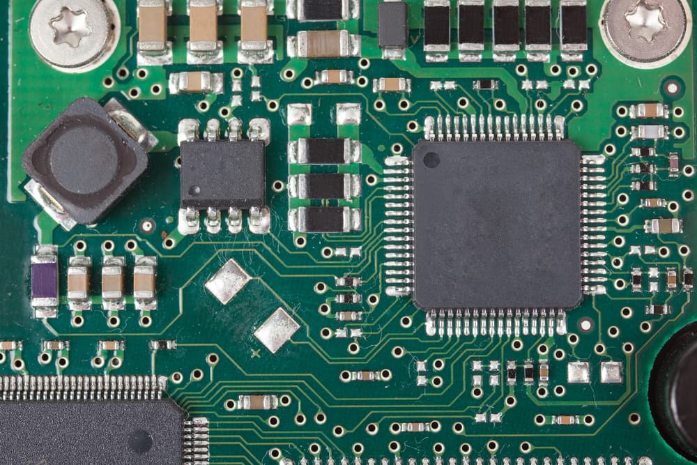
Figure 6: 74LS76 in a Memory Circuit
The 74LS76 is a useful JK flip-flop integrated circuit (IC) that is widely used in different types of digital circuits. Its main job is to store binary data (0s and 1s) and hold its state until new input changes that state. Below are some of the main ways the 74LS76 is applied in digital systems:
Shift Registers
In digital circuits, shift registers are used to move data from one place to another in a specific order, usually one bit at a time. The 74LS76 is good for this job because its JK flip-flop setup can hold each bit of data and move it when the clock signal is given. This ability is useful in devices that need to convert data from parallel form (many bits at once) to serial form (one bit at a time) or vice versa. For example, in digital communication systems, data often needs to be sent in a sequence, and the 74LS76 helps with this task by shifting bits correctly through the circuit.
Memory and Control Registers
The 74LS76 is often used in computers and microprocessors as part of memory and control registers. These registers act like temporary holding areas for data that the processor is currently working with. Control registers hold information that tells the processor how to operate or what to do next, while memory registers store data that is being calculated or processed. The 74LS76 works well here because its flip-flop design allows it to store data in a stable way until the processor needs it.
Counters
The 74LS76 is also commonly used in counters, which are devices that count things like the number of pulses from a clock signal or the number of events happening over time. Counters are used to create devices that manage timing, measure frequencies, or track how many times something occurs. The 74LS76 flip-flop changes its state with each clock pulse, which allows it to count upward or downward, depending on how it is connected in the circuit.
Latches
In some situations, it's necessary to hold a specific piece of data until a new command or signal tells the circuit to change it. This is where the 74LS76 is handy in latch circuits. A latch circuit holds onto a piece of data until an input tells it to change. This feature is useful in systems that need to keep an output steady, such as when holding memory addresses or managing temporary data buffers in communication systems.
EEPROM Circuits
The 74LS76 can also be used in circuits with EEPROM (Electrically Erasable Programmable Read-Only Memory), which are memory chips that can be written to and erased electrically. While the 74LS76 does not store data itself, it helps manage the signals that control the flow of data to and from the EEPROM. The flip-flop structure of the 74LS76 helps keep track of important control signals and ensures the proper timing for reading or writing data, which helps the EEPROM work properly.
Equivalent ICs and Alternatives
If the 74LS76 is not available, other integrated circuits can be used to do the same job. Some commonly used equivalent ICs include the 74LS73, MC74HC73A, and SN7476. These ICs have similar functions and can often be used in place of the 74LS76. Other alternative JK flip-flop chips, such as the 74LS107 and 4027B, can also serve the same purpose in most circuits. While these alternatives might have slight differences in how they work, such as needing more or less power or running at different speeds, they can generally be swapped in without causing problems for the circuit.
Conclusion
74LS76 is a useful JK flip-flop chip that helps store and control data in digital circuits. Its two flip-flops, along with various input and output controls, allow it to handle binary data and work with timing signals effectively. This makes it a common choice for tasks like counting, storing memory, and shifting data from one place to another. By learning about its pin connections and how it operates, you can see how the 74LS76 fits into a wide range of electronics projects. Whether you're building a counter, managing memory, or processing signals, this chip can help you do it in an efficient and reliable way.
Frequently Asked Questions [FAQ]
1. What are the key features and functions of the 74LS76 Dual JK Flip-Flop?
The 74LS76 is a small chip that has two separate JK flip-flops inside. These flip-flops can store and change binary data (either 0 or 1). The main features include inputs labeled J and K, a clock input, and special preset and clear functions. It reacts to changes in the clock signal, meaning it changes when the clock signal moves from low to high or high to low. It’s used for storing data, flipping between two states, and counting in digital circuits.
2. How does the clock input affect the operation of the 74LS76 JK Flip-Flop?
The clock input controls when the flip-flop will check the J and K inputs to decide if it should change its state. The flip-flop will only change at the exact moment when the clock signal rises or falls. If there is no clock signal change, the flip-flop holds onto its current state. So, the clock input is what triggers or “activates” the flip-flop to do its job at the right time.
3. What are the pin configurations and their roles in the 74LS76 Dual JK Flip-Flop?
The 74LS76 has 16 pins, with each flip-flop inside the chip having its own set of inputs and outputs. The J and K pins decide how the flip-flop will behave (set or reset). The clock (CLK) pin triggers the change in state. The preset (PRE) and clear (CLR) pins force the output to be 1 (on) or 0 (off) instantly, without waiting for the clock signal. The outputs are Q and Q’, where Q’ is just the opposite of Q. There are also pins for connecting power (Vcc) and ground (GND).
4. How can the 74LS76 be used in designing counters and digital circuits?
The 74LS76 is often used to make counters by connecting more than one flip-flop in a row. The output of one flip-flop can trigger the next, allowing them to count in binary, which means going through a sequence of 0s and 1s. The flip-flop’s toggle feature, which happens when both J and K are set to high, makes it very useful for digital circuits that need to count or switch states in an organized way, like frequency dividers or systems that track the order of steps.
5. What are the common applications and alternatives for the 74LS76 JK Flip-Flop?
The 74LS76 is used in devices like memory storage, frequency dividers, binary counters, and shift registers. These are all tools that work with binary data, counting, or shifting bits around. If the 74LS76 isn’t available, there are other chips like the 74LS73, 74LS107, and SN7476 that can do the same job. They have similar features but may use slightly different amounts of power or respond to signals in a slightly different way.
About us
ALLELCO LIMITED
Read more
Quick inquiry
Please send an inquiry, we will respond immediately.
The 500 Ohm Resistor: Key Features & Practical Uses
on September 11th
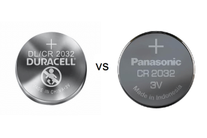
DL2032 Vs. CR2032
on September 11th
Popular Posts
-

What is GND in the circuit?
on January 1th 3036
-

RJ-45 Connector Guide: RJ-45 Connector Color Codes, Wiring Schemes, R-J45 Applications, RJ-45 Datasheets
on January 1th 2606
-

Fiber Connector Types: SC Vs LC And LC Vs MTP
on January 1th 2162
-

Understanding Power Supply Voltages in Electronics VCC, VDD, VEE, VSS, and GND
on November 13th 2064
-

Comparison Between DB9 and RS232
on January 1th 1788
-

What Is An LR44 Battery?
Electricity, that ubiquitous force, quietly permeates every aspect of our daily lives, from trivial gadgets to life-threatening medical equipment, it plays a silent role. However, truly grasping this energy, especially how to store and efficiently output it, is no easy task. It is against this background that this article will focus on a type of coin cell battery that may seem insignificant on the...on January 1th 1754
-

Understanding the Fundamentals:Inductance Resistance, andCapacitance
In the intricate dance of electrical engineering, a trio of fundamental elements takes center stage: inductance, resistance, and capacitance. Each bears unique traits that dictate the dynamic rhythms of electronic circuits. Here, we embark on a journey to decipher the complexities of these components, to uncover their distinct roles and practical uses within the vast electrical orchestra. Inductan...on January 1th 1704
-

CR2430 Battery Comprehensive Guide: Specifications, Applications and Comparison to CR2032 Batteries
What is CR2430 battery ?Benefits of CR2430 BatteriesNormCR2430 Battery ApplicationsCR2430 EquivalentCR2430 VS CR2032Battery CR2430 SizeWhat to look for when buying the CR2430 and equivalentsData Sheet PDFFrequently Asked Questions Batteries are the heart of small electronic devices. Among the many types available, coin cells play a crucial role, commonly found in calculators, remote controls, and ...on January 1th 1640
-

What Is RF and Why Do We Use It?
Radio Frequency (RF) technology is a key part of modern wireless communication, enabling data transmission over long distances without physical connections. This article delves into the basics of RF, explaining how electromagnetic radiation (EMR) makes RF communication possible. We will explore the principles of EMR, the creation and control of RF signals, and their wide-ranging uses. The article ...on January 1th 1618
-

Comprehensive guide to hFE in transistors
Transistors are crucial components in modern electronic devices, enabling signal amplification and control. This article delves into the knowledge surrounding hFE, including how to select a transistor's hFE value, how to find hFE, and the gain of different types of transistors. Through our exploration of hFE, we gain a deeper understanding of how transistors work and their role in electronic circu...on November 13th 1561
HOT Part Number
-

1N5335B
Microsemi Corporation
DIODE ZENER 3.9V 5W T18
VI-263-IY
Vicor Corporation
DC DC CONVERTER 24V 50W
TSV632IDT
STMicroelectronics
IC OPAMP GP 2 CIRCUIT 8SOIC
AS1217MY
onsemi
INTEGRATED CIRCUIT
ADA4807-2ARMZ
Analog Devices Inc.
IC VOLTAGE FEEDBACK 2 CIRC 8MSOP
BCM5482SHEA2KFBG
Broadcom Limited
DUAL PORT 10/100/1000BASE-T PH S
URB2415LD-30WR3
Mornsun America, LLC
DC DC CONVERTER 15V 30W
QMK325B7224KN-L
Taiyo Yuden
CAP CER 0.22UF 250V X7R 1210
C4532X5R1A476M280KA
TDK Corporation
CAP CER 47UF 10V X5R 1812
MAX1617MEE
Analog Devices Inc./Maxim Integrated
SENSOR DIGITAL -55C-125C 16QSOP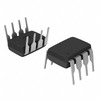
OPA2658P
Texas Instruments
IC OPAMP CFB DUAL WIDEBAND 8DIP
GRM2165C2A182JA01J
Murata Electronics
CAP CER 1800PF 100V C0G/NP0 0805
SMAJ12A-TR
STMicroelectronics
TVS DIODE 12VWM 25.3VC SMA
TC213L8F133FACKXUMA1
Infineon Technologies
IC MCU 32BIT 512KB FLASH 100TQFP
08052A471JAT4A
KYOCERA AVX
CAP CER 470PF 200V C0G/NP0 0805
C3216CH2J391K060AA
TDK Corporation
CAP CER 390PF 630V CH 1206
TPS389001DSER
Texas Instruments
IC SUPERVISOR 1 CHANNEL 6WSON
BZX84C30S-7-F
Diodes Incorporated
DIODE ZENER ARRAY 30V SOT363 -

DMN2015UFDE-7
Diodes Incorporated
MOSFET N-CH 20V 10.5A 6UDFN
K32W041AMZ
NXP USA Inc.
IC MCU K32W041 MCM 40HVQFN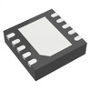
LT3485EDD-2#PBF
Analog Devices Inc.
IC CHARGER PHOTOFLASH 10-DFN
SI8231BB-D-ISR
Skyworks Solutions Inc.
DGTL ISO 2.5KV GATE DRVR 16SOIC
THS4062CDR
Texas Instruments
IC VOLTAGE FEEDBACK 2 CIRC 8SOIC
AD9058AJD
Analog Devices Inc.
IC ADC 8BIT FLASH 48CDIP
VI-711610B
Vicor Corporation
DC DC CONVERTER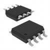
DMN3112SSS-13
Diodes Incorporated
MOSFET N-CH 30V 6A 8SOP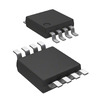
MAX4377HAUA
Analog Devices Inc./Maxim Integrated
IC CURRENT SENSE 2 CIRCUIT 8UMAX
C3216X7R2E683K160AA
TDK Corporation
CAP CER 0.068UF 250V X7R 1206
GRM033R71E331KA01J
Murata Electronics
CAP CER 330PF 25V X7R 0201
TF252TH-4-TL-H
onsemi
JFET N-CH 1MA 3VTFP
GRM0225C1E8R8DA03L
Murata Electronics
CAP CER 8.8PF 25V C0G/NP0 01005
1808CC102KAT9A
KYOCERA AVX
CAP CER 1000PF 630V X7R 1808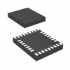
LP3936SLX
Texas Instruments
IC LED DRV RGLTR PWM 32TLGA
VOL617A-3T
Vishay Semiconductor Opto Division
OPTOISOLATOR 5KV TRANS 4-LSOP
74F14PC
Fairchild Semiconductor
IC INVERT SCHMITT 6CH 1-IN 14DIP
STM1811LWX7F
STMicroelectronics
IC SUPERVISOR 1 CHANNEL SOT23-3 -

T627081564DN
Powerex Inc.
SCR 800V 235A T62
08055C473KAT2P
KYOCERA AVX
CAP CER 0.047UF 50V X7R 0805
PEF42065HLV1.2
Lantiq
XWAY SMART SLIC-R VOIP ACCESS SO
SE15PDHM3/84A
Vishay General Semiconductor - Diodes Division
DIODE GEN PURP 200V 1.5A DO220AA
LM3671MF-1.2
Texas Instruments
IC REG BUCK 1.2V 600MA SOT23-5
9007-05-00
Coto Technology
RELAY REED SPST 500MA 5V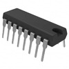
CD74HC238E
Texas Instruments
IC DECODER/DEMUX 1X3:8 16DIP
FAR-G5KK-911M50-D4KE-Z
Taiyo Yuden
FILTER SAW 911.5MHZ 10SMD
74HC132PW,118
NXP USA Inc.
IC GATE NAND 4CH 2-INP 14-TSSOP
MT25QL256ABA1EW9-0SIT
Micron Technology Inc.
IC FLASH 256MBIT SPI 8WPDFN
PM8562B-F3EI
Microchip Technology
IC INTERFACE SPECIALIZED PFX-L
CL10X475KQ8NNNC
Samsung Electro-Mechanics
CAP CER 4.7UF 6.3V X6S 0603
CL21F106ZQFNNNF
Samsung Electro-Mechanics
CAP CER 10UF 6.3V Y5V 0805
X9400WS24IZ-2.7T1
Renesas Electronics America Inc
IC DGTL POT 10KOHM 64TAP 24SOIC
TC1017-2.9VCTTR
Microchip Technology
IC REG LINEAR 2.9V 150MA SOT23-5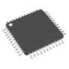
PIC16C74B-20I/PT
Microchip Technology
IC MCU 8BIT 7KB OTP 44TQFP
TEST2600
Vishay Semiconductor Opto Division
PHOTOTRANSISTOR 850 TO 980 NM
MX25L8006EM1J-12G
Macronix
IC FLASH 8MBIT SPI 86MHZ 8SOP