Understanding Three-Phase Transformer Connections in Electrical Power Systems
In the industrial and commercial sectors, three-phase transformers play a role for the effective transmission and distribution of electrical power. By combining three single-phase transformers into one unit, they reduce costs, size, and weight. These transformers ensure even distribution of electrical energy between high and low voltage windings, regardless of their construction type. This article explains their construction, operation, and connection configurations, helping you to understand their functionality and applications. It starts with core-type and shell-type designs, which manage magnetic flux and minimize energy losses. It also covers operational principles, magnetic flux balancing, and connection types like delta/delta, delta/wye, wye/delta, and wye/wye, along with specialized connections like Scott and zig-zag. Examples and comparisons between dry-type and liquid-filled transformers are provided to help engineers choose the right transformer for optimal performance and reliability.
Catalog
Three-Phase Transformer Construction
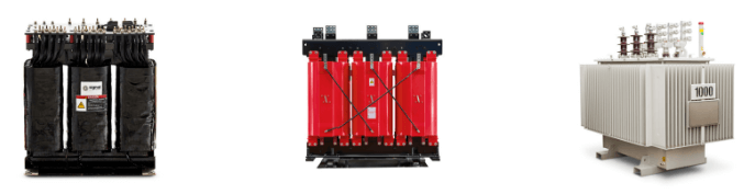
Figure 1: Three Phase Transformer Construction
They combine three single-phase transformers into one, saving money, space, and weight. The core has three magnetic circuits that balance the magnetic flow between high and low voltage parts. This design is different from three-phase shell-type transformers, which group three cores together but don’t merge them. It makes the system more efficient and reliable compared to single-phase systems.
A common design for three-phase transformers is the three-limb core-type. Each limb supports its own magnetic flow and acts as a return path for the others, creating three flows that are each 120 degrees out of phase. This phase difference keeps the magnetic flow's shape almost sinusoidal, which ensures a stable output voltage, reduces distortions and losses, and improves performance and lifespan. This simple and effective design is popular for standard uses.
Core Type
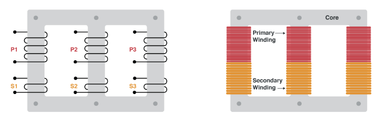
Figure 2: Core Type
In core type construction for three-phase transformers, the design focuses on three main cores, each paired with two yokes. This structure effectively distributes magnetic flux. Each core supports primary and secondary windings, which are coiled in a spiral around the core legs. This setup ensures that each leg carries both high voltage (HV) and low voltage (LV) windings, balancing the electrical load and magnetic flux distribution.
Another feature of core type transformers is reducing eddy current losses. Eddy currents, induced within conductors by a changing magnetic field, can cause energy losses and reduce efficiency. To minimize these losses, the core is laminated. This involves stacking thin layers of magnetic material, each insulated from the others, to confine the eddy currents and reduce their impact.
The positioning of windings is another design aspect. Low voltage windings are placed closer to the core. This placement simplifies insulation and cooling, as LV windings operate at lower voltages, requiring less insulation. Insulation and oil ducts are introduced between the LV windings and the core to enhance cooling and prevent overheating, ensuring the transformer's longevity.
High voltage windings are placed above the LV windings, also insulated and spaced with oil ducts. These oil ducts are best for cooling and maintaining the effectiveness of the insulation system under high voltage. This detailed arrangement of windings and laminated core allows core type transformers to handle high voltages efficiently, with minimal energy losses and high stability. These design principles make core type transformers ideal for applications requiring efficient magnetic flux management and high voltage operation.
Shell Type
Shell type transformers offer a different approach to three-phase transformer construction, characterized by a unique design and operational benefits. This design involves stacking three individual single-phase transformers to form a three-phase unit, unlike core type transformers where the phases are interdependent. In shell type transformers, each phase has its own magnetic circuit and operates independently. The independent magnetic circuits are arranged parallel to each other, ensuring that the magnetic fluxes are in phase but do not interfere with one another. This separation contributes greatly to the transformer’s stability and consistent performance.
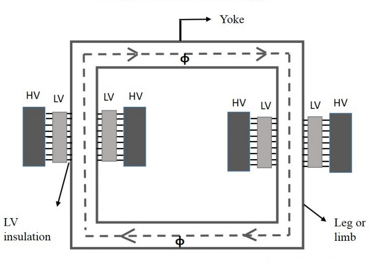
Figure 3: Shell Type
Advantage of shell type transformers is reduced waveform distortion. The independent operation of each phase results in cleaner and more stable voltage waveforms compared to core type transformers. This is important in applications where voltage quality is compromised, such as in sensitive industrial and commercial systems where distortion can lead to equipment malfunction.
Shell type transformers are also efficient. Each phase can be optimized for its specific load conditions independently, enhancing reliability and efficiency. The reduced waveform distortion minimizes harmonic losses, further improving the transformer's efficiency and lifespan.
The construction and operation of both core type and shell type transformers helps engineers and technicians choose the right transformer for their electrical systems. Whether the need is for handling high voltages, minimizing energy losses, or ensuring stable voltage supply, selecting the appropriate transformer type ensures optimal performance.
Working of Three-Phase Transformers
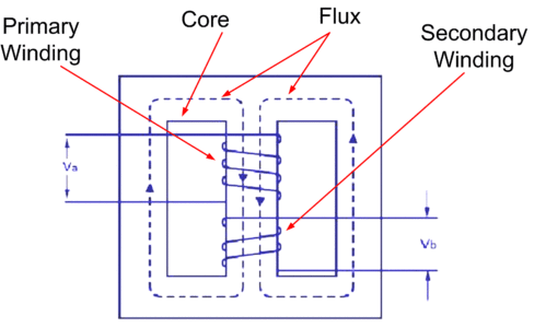
Figure 4: Working of Three Phase Transformer
Three cores spaced 120 degrees apart are used in three-phase transformers to guarantee effective interaction of the magnetic fluxes generated by the primary windings. The transformer's core handles magnetic flux generated by currents IR, IY, and IB in the primary windings. These currents create magnetic fluxes ɸR, ɸY, and ɸB. Connected to a three-phase power supply, these currents induce magnetic flux in the cores.
In a balanced system, the sum of the three-phase currents (IR + IY + IB) is zero, leading to zero combined magnetic flux (ɸR + ɸY + ɸB) in the center leg. Thus, the transformer can function without the center leg, as the other legs handle the flux independently. Three-phase transformers distribute power evenly across three phases, reducing energy losses and enhancing power supply stability. Flux balance in the core structure required for efficient transformer operation. The distribution of magnetic flux within the core of a three-phase transformer must be balanced for it to function. The 120-degree placement of cores and precise induction of currents ensure efficient operation.
Three-Phase Transformer Connections
To meet different requirements, three-phase transformer windings can be coupled in a variety of ways. "Star" (wye), "delta" (mesh), and "interconnected-star" (zig-zag) are the three primary types of connections. Combinations can include primary delta-connected with secondary star-connected, or vice versa, depending on the application.
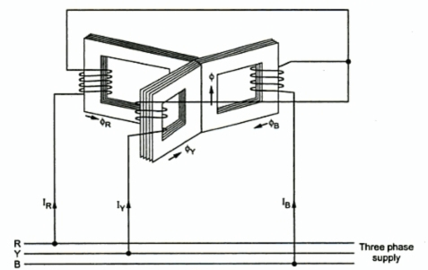
Figure 5: Three-Phase Transformer Connections
Delta/Delta Connection
The delta/delta connection is widely used when a single secondary voltage is require or when the primary load mainly consists of three-phase equipment. This setup is common in industrial settings with large three-phase motor loads operating at 480 V or 240 V, and with minimal 120 V lighting and receptacle needs. The turns ratio between the primary and secondary windings aligns with the required voltages, making this setup less suitable for different voltage transformations.
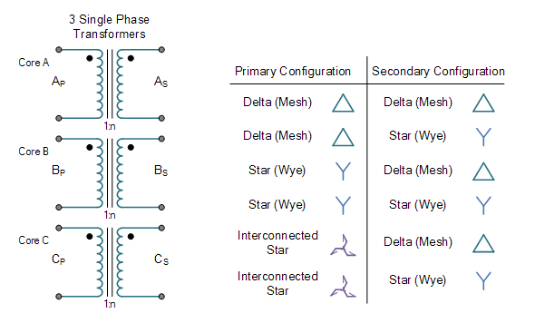
Figure 6: Symbol for Delta/Delta Transformer
Figure 7: Connection Diagram for Delta/Delta Transformer
Advantages
The delta/delta connection offers several advantages. One benefit is the reduced phase current, which is only 57.8% of the line current. This reduction allows for smaller conductors for each single-phase transformer compared to the line conductors supplying the three-phase load, lowering material costs and simplifying the system. Additionally, harmonic currents tend to cancel out, improving the transformer's ability to isolate electrical noise between primary and secondary circuits. This results in a stable secondary voltage with minimal fluctuations during load surges. If a single-phase transformer fails, the system can still deliver three-phase voltage through an open delta configuration, albeit at a reduced capacity of 58%.
Disadvantages
Despite these benefits, the delta/delta connection has notable drawbacks. It provides only one secondary voltage, which may require additional transformers for different voltage needs, increasing system complexity and cost. The primary winding conductors must be insulated for the full primary voltage, necessitating extra insulation for high-voltage applications. Another disadvantage is the lack of a common ground point on the secondary side, which can lead to high voltages to ground, posing safety risks and potential equipment damage.
Delta/Wye Connection
The delta/wye connection is a common transformer setup used on different secondary voltages. It's great for systems that need to provide various voltage levels at the same time. For example, in factories and commercial buildings, there's often a need for high voltage for heavy machinery and lower voltage for lighting and general use outlets. A typical use might include providing 208 V for motors and 120 V for lights and outlets. The delta/wye connection can handle these different voltage needs well.
In this setup, the primary winding is in a delta (Δ) shape, and the secondary winding is in a wye (Y) shape. The delta connection on the primary side is good for handling high power loads, giving a strong and stable power supply. This is useful in industrial settings with large motors and heavy equipment. The delta arrangement also helps reduce certain types of electrical noise, ensuring a cleaner power supply to the connected devices.
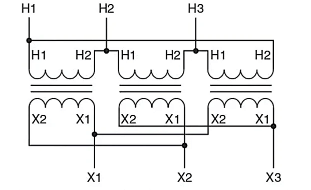
Figure 8: Symbol for Delta/Wye Transformer

Figure 9: Connection Diagram for Delta/Wye Transformer
Advantages
The wye connection allows the secondary line voltage to be 1.73 times greater with the same number of turns on the primary and secondary windings of each single-phase transformer, which is beneficial for step-up transformer applications. The secondary windings require less insulation since they do not need to be insulated for the full secondary line voltage. The availability of multiple voltages on the secondary side can eliminate the need for additional transformers to supply 120 V loads in a three-phase system with a 208 V line voltage. Benefit is the presence of a common point on the secondary side to ground the system, limiting the voltage potential to ground and preventing it from exceeding the secondary-phase voltage.
Disadvantages
However, the delta/wye connection has its disadvantages. The primary windings must be insulated for the full three-phase line voltage, requiring extra insulation, especially for high-voltage step-down applications. The secondary wye connection does not cancel out harmonic currents, impacting the transformer's stability and efficiency. The secondary windings have to carry the entire three-phase line current, which means that they have to be bigger than in a delta system with the same capacity.
Wye/Delta Connection
The Y/Δ transformer connection, also called the wye/delta connection, is a common setup in electrical power systems. It's useful when you need a single secondary voltage or when the main load is three-phase equipment like industrial motors and heavy machines. This setup is also often used in step-down transformers to lower high primary voltages to safer and more efficient lower secondary voltages.
In this connection, the primary windings are arranged in a wye (Y) shape, with each winding connected to a common neutral point, which is usually grounded. The secondary windings are arranged in a delta (Δ) shape, forming a loop. Phase relationships and voltage levels are stabilized while three-phase power is transformed with the aid of this setup.
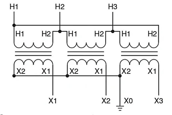
Figure 10: Symbol for Wye/Delta Transformer
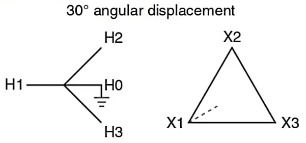
Figure 11: Connection Diagram for Wye/Delta Transformer
Advantages
The turns ratio results in a secondary line voltage that is reduced by a factor of 1.73 (or 57.8%) due to the wye connection, making it beneficial for step-down transformer applications. This ensures that secondary harmonic currents cancel out, providing excellent noise isolation between primary and secondary circuits. The primary windings do not need to be insulated for the full three-phase line voltage, potentially reducing insulation requirements when stepping down from high voltages. Three-phase power can still be delivered using an open delta system in the event of a single-phase transformer failure, but at a 58% lower capacity.
Disadvantages
Wye/delta connection has its disadvantages. Like the delta/delta connection, it only offers a single secondary voltage, requiring additional transformers to supply lighting and receptacle loads. There is no common ground point on the secondary side, leading to high voltages to ground. The primary winding conductors must carry the full three-phase line current, necessitating larger conductors compared to a delta-connected primary of the same capacity. Lastly, the common point of the wye primary windings should be connected to a system neutral to avoid voltage fluctuations with unbalanced loads.
Wye/Wye Connection
The wye/wye transformer connection is rarely used due to its noise transfer, harmonic distortion, communication interference, and phase voltage instability. In a wye/wye setup, the neutral points of both the primary and secondary windings are grounded. While this grounding provides a reference point and can help balance loads, it also allows noise to transfer between the primary and secondary circuits. This means any electrical noise on one side can easily move to the other, harming sensitive electronic equipment and causing inefficiencies.
Wye/wye connections are prone to harmonics, which are unwanted frequencies that distort electrical currents and voltages. Harmonics can come from non-linear loads like rectifiers and variable frequency drives. Unlike other configurations such as delta/wye, wye/wye transformers do not cancel out these harmonics effectively.
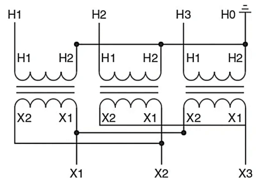
Figure 12: Symbol for Wye/Wye Transformer
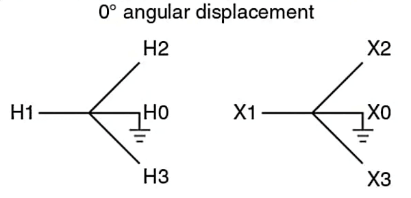
Figure 13: Connection Diagram for Wye/Wye Transformer
Disadvantages
• Sensitive to unbalanced loads, causing unbalanced currents in the windings, which can lead to overheating and reduced efficiency.
• Circulating neutral currents can occur, particularly with unbalanced loads, requiring additional protection measures.
• Grounding a wye/wye transformer is more complex compared to other configurations, resulting in ground loops and safety hazards.
• Voltage distortion from harmonic currents generated by non-linear loads can affect the performance of sensitive equipment and may necessitate additional filtering or mitigation measures.
• Implementing a wye/wye transformer can be more expensive due to the complexity of the connections and the additional measures involved to address issues such as unbalanced loads and neutral currents.
Open Delta or V-V Connection
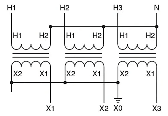
Figure 14: Open Delta or V-V Connection
Two single-phase transformers are used in an open delta connection. This setup is useful when one transformer breaks down or needs maintenance. Even though the initial setup used three transformers, the remaining two can still provide three-phase power but at a reduced capacity of 58%.
In this arrangement, the primary windings of the two transformers are connected in a delta with one leg open. The phase voltages Vab and Vbc are produced in the secondary windings of the two transformers, while Vca is created from the secondary voltages of the other two transformers. This way, a three-phase power supply can keep working with just two transformers instead of three.
When you switch from a balanced delta-delta connection to an open delta, each transformer has to handle much more current. This increase is about 1.73 times the normal amount, which can overload the transformers by 73.2% more than their normal capacity. To prevent overheating and damage during maintenance, you should reduce the load by the same factor of 1.73.
If one phase is expected to go out, the open delta connection can be used to keep things running while you work on the transformers.
Scott Connection
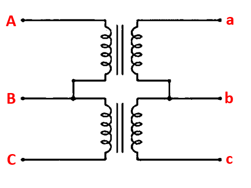
Figure 15: Scott Connection
To create two-phase voltages with a 90° phase shift, the Scott connection of a three-phase transformer uses two transformers: one has a center tap on both windings, and the other has an 86.6% tap. This setup allows the conversion of power between single- and three-phase systems with just two transformers.
The two transformers are magnetically separate but electrically connected. The auxiliary transformer connects in parallel with a 30° phase shift, while the main transformer gets the three-phase supply voltages on its primary winding. For single-phase loads, the windings are connected in parallel on the secondary side. The source voltage goes to the combined secondaries to change single-phase to three-phase, giving a balanced three-phase output.
By keeping transformer cores separate, this magnetic separation allows two transformers to create the third phase voltage needed for three-phase electricity without overloading. For changing single-phase to three-phase or three-phase to single-phase voltage with fewer parts, the Scott connection is a cost-effective choice. The Scott connection is often used to convert three-phase systems to two-phase systems.
Zig-Zag Three-Phase Connection
The zig-zag transformer connection involves splitting each phase winding into two equal halves, with the first half on one core and the second half on another core. This pattern repeats for each phase, resulting in parts of two phases on each limb, with one winding on each limb connected at the endpoints.
When balanced voltages are applied, the system remains passive, with induced voltages canceling each other, establishing the transformer as a high impedance to positive and negative sequence voltages. During unbalanced states, such as ground faults, the windings provide a low impedance path for zero sequence currents, splitting the current evenly into three and returning it to the respective phases. The impedance can be adjusted to set the maximum ground-fault current, or the transformer can be used with a ground resistor to maintain a consistent value across a medium-voltage system.
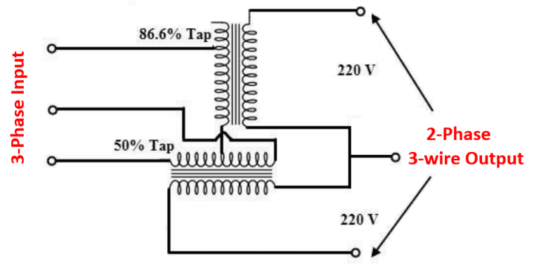
Figure 16: Zig-Zag Three-Phase Connection
Dry-Type and Liquid-Filled Transformers
Three-phase transformers fall into two main categories: dry-type transformers and liquid-filled transformers. Each type has unique characteristics based on their cooling methods and construction.
Dry-Type Transformers
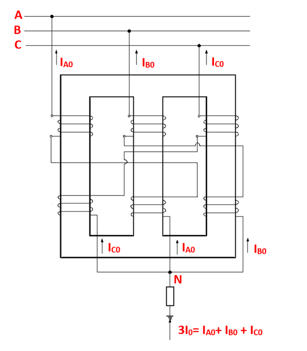
Figure 17: Dry-Type Transformer
Dry-type transformers use air for cooling. They are divided into open frame transformers and cast-resin coil transformers.
Open Frame Transformers: Open frame transformers have exposed resin-impregnated cores and coils and are designed for enclosed spaces. They typically handle voltages up to 1000V and power up to 500 kVA. Their design allows efficient cooling, making them suitable for environments that require low noise and minimal maintenance. However, their exposed nature necessitates a controlled environment to avoid contamination.
Cast-Resin Coil Transformers: In cast-resin coil transformers, each coil is solidly cast in epoxy, providing better protection and reliability. They can handle voltages up to 36.0 kV and power up to 40 MVA. The epoxy encapsulation offers excellent insulation, mechanical strength, and resistance to moisture and contaminants. This makes them ideal for industrial and outdoor settings.
Liquid-Filled Transformers
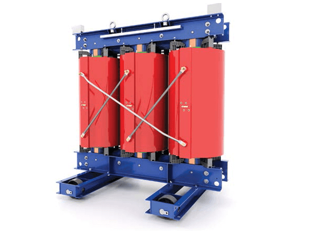
Figure 18: Liquid-Filled Transformer
Liquid-filled transformers are immersed in mineral oil inside vacuum-sealed metal containers. The oil serves as a cooling and insulating medium. These transformers are suitable for higher power and voltage applications, with ratings ranging from 6.0 kV to 1,500 kV and power up to 1000+ MVA. The mineral oil provides superior cooling efficiency and insulation, making them ideal for high-demand industrial and utility applications.
The vacuum-sealed containers protect the components from environmental factors, ensuring durability and reliability. Liquid-filled transformers are preferred for large-scale power distribution due to their ability to handle high loads and maintain stable performance. In order to keep things running smoothly and avoid overheating, heat must be adequately dissipated via the oil immersion.
Conclusion
Three-phase transformers construction, whether core-type or shell-type, valuable on managing magnetic flux and reducing losses. Core-type transformers are suitable for high-voltage operations, while shell-type transformers offer better waveform stability and efficiency. Their operational principles, including balanced magnetic flux distribution and 120-degree core placement, ensure efficiency and reduced energy losses. Specialized connections, such as Scott and zig-zag, enhance their versatility for specific applications. Choosing between dry-type and liquid-filled transformers depends on cooling needs, voltage levels, and environmental conditions. Understanding the technical details and benefits of different transformer types and configurations enables engineers to optimize power systems for stability, efficiency, and longevity.
Frequently Asked Questions [FAQ]
1. What happens if a 3-phase motor loses a phase?
When a 3-phase motor loses one of its phases, the condition is known as single phasing. The motor will try to continue operating, but it will experience several adverse effects. First, the motor will produce less power and run with increased vibration and noise. It will also draw more current on the remaining two phases, leading to overheating and potential damage to the motor windings. If left running under these conditions, the motor can suffer damage, and its lifespan will be reduced. Practically, operators will notice an unusual humming sound, reduced performance, and possibly an increase in temperature of the motor casing.
2. What are three-phase transformers normally connected in?
Three-phase transformers are connected in either a delta (Δ) or wye (Y) configuration. The delta connection forms a closed loop with each transformer winding connected end-to-end, creating a triangle. The wye connection connects each transformer winding to a common neutral point, forming a 'Y' shape. These configurations affect the voltage levels, the distribution of loads, and the method of grounding in the electrical system.
3. What are the terminals of a 3-phase transformer?
A 3-phase transformer has six terminals on the primary side and six on the secondary side. These terminals correspond to the three phases (A, B, and C) and their respective ends (H1, H2, H3 for the primary side and X1, X2, X3 for the secondary side). If the transformer is configured in a wye (Y) connection, there may also be a neutral terminal on both the primary and secondary sides.
4. How many wires does a 3-phase transformer have?
A 3-phase transformer has three primary wires and three secondary wires if connected in delta-delta or delta-wye configuration. If it is connected in wye-wye or wye-delta configuration, there may be an additional neutral wire on either the primary side, the secondary side, or both. Thus, it can have between three to four wires on each side, depending on the configuration and the presence of neutral connections.
5. How many cables for 3-phase?
A 3-phase system uses three power cables, each carrying one phase of the electrical supply. If the system includes a neutral wire, it will have four cables in total. For systems that include an earth (ground) wire, there may be five cables altogether: three phase wires, one neutral wire, and one ground wire.
6. What happens if one phase of a 3-phase transformer fails?
If one phase of a 3-phase transformer fails, it can lead to several problems. The transformer will be unable to supply balanced three-phase power, resulting in an unbalanced load. This condition can cause overheating, increased current in the remaining phases, and possible damage to connected equipment. The power quality will deteriorate, leading to potential malfunction or failure of devices relying on three-phase power. Operators will notice a drop in performance, increased noise, and possible overloading of the electrical system.
7. What is the most common 3-phase connection?
The most common 3-phase connection is the delta-wye (Δ-Y) connection. In this configuration, the primary winding is connected in a delta arrangement, and the secondary winding is connected in a wye arrangement. This setup is widely used because it allows for the transformation of voltages and provides a neutral point for grounding, which enhances safety and stability in the electrical distribution system.
8. Mention the applications of 3-phase transformers.
Power Distribution: They are valuable in the transmission and distribution of electrical power over long distances, reducing voltage levels for safe residential, commercial, and industrial use.
Industrial Equipment: Many industrial machines and motor drives require three-phase power for efficient operation, making these transformers good in industrial settings.
HVAC Systems: Large heating, ventilation, and air conditioning systems often use three-phase power for their compressors and motors.
Renewable Energy Systems: They are used in renewable energy setups, such as wind and solar power plants, to transform and distribute generated power efficiently.
Electrical Grids: They play role in substations and power grids, stepping down high transmission voltages to lower distribution levels.
About us
ALLELCO LIMITED
Read more
Quick inquiry
Please send an inquiry, we will respond immediately.

Understanding Power Supply Voltages in Electronics VCC, VDD, VEE, VSS, and GND
on June 29th
The Future of Energy: Exploring Solar Photovoltaic (PV) Power Systems
on June 28th
Popular Posts
-

What is GND in the circuit?
on January 1th 2942
-

RJ-45 Connector Guide: RJ-45 Connector Color Codes, Wiring Schemes, R-J45 Applications, RJ-45 Datasheets
on January 1th 2501
-

Fiber Connector Types: SC Vs LC And LC Vs MTP
on January 1th 2089
-
Understanding Power Supply Voltages in Electronics VCC, VDD, VEE, VSS, and GND
on November 9th 1895
-

Comparison Between DB9 and RS232
on January 1th 1765
-

What Is An LR44 Battery?
Electricity, that ubiquitous force, quietly permeates every aspect of our daily lives, from trivial gadgets to life-threatening medical equipment, it plays a silent role. However, truly grasping this energy, especially how to store and efficiently output it, is no easy task. It is against this background that this article will focus on a type of coin cell battery that may seem insignificant on the...on January 1th 1714
-

Understanding the Fundamentals:Inductance Resistance, andCapacitance
In the intricate dance of electrical engineering, a trio of fundamental elements takes center stage: inductance, resistance, and capacitance. Each bears unique traits that dictate the dynamic rhythms of electronic circuits. Here, we embark on a journey to decipher the complexities of these components, to uncover their distinct roles and practical uses within the vast electrical orchestra. Inductan...on January 1th 1655
-

CR2430 Battery Comprehensive Guide: Specifications, Applications and Comparison to CR2032 Batteries
What is CR2430 battery ?Benefits of CR2430 BatteriesNormCR2430 Battery ApplicationsCR2430 EquivalentCR2430 VS CR2032Battery CR2430 SizeWhat to look for when buying the CR2430 and equivalentsData Sheet PDFFrequently Asked Questions Batteries are the heart of small electronic devices. Among the many types available, coin cells play a crucial role, commonly found in calculators, remote controls, and ...on January 1th 1555
-

What Is RF and Why Do We Use It?
Radio Frequency (RF) technology is a key part of modern wireless communication, enabling data transmission over long distances without physical connections. This article delves into the basics of RF, explaining how electromagnetic radiation (EMR) makes RF communication possible. We will explore the principles of EMR, the creation and control of RF signals, and their wide-ranging uses. The article ...on January 1th 1541
-

CR2450 vs CR2032: Can The Battery Be Used Instead?
Lithium manganese batteries do have some similarities with other lithium batteries. High energy density and long service life are the characteristics they have in common. This kind of battery has won the trust and favor of many consumers because of its unique safety. Expensive tech gadgets? Small appliances in our homes? Look around and you'll see them everywhere. Among these many lithium-manganes...on January 1th 1512
HOT Part Number
-
LT1790BIS6-2.048#TRMPBF
Analog Devices Inc.
IC VREF SERIES 0.1% TSOT23-6
CC0402JRX7R8BB332
YAGEO
CAP CER 3300PF 25V X7R 0402
ADV212BBCZ-115
Analog Devices Inc.
IC CODEC VID JPEG 2000 121CSBGA
BQ51003YFPR
Texas Instruments
IC WIRELESS PWR RCVR 28DSBGA
VT245AWFQX-ADJ
Analog Devices Inc./Maxim Integrated
IC REG LINEAR QFN SMD
NCV3064DR2G
onsemi
IC REG BUCK BST ADJ 1.5A 8SOIC
FSL126MR
onsemi
IC OFFLINE SWITCH FLYBACK 8DIP
ADS831E
Texas Instruments
IC ADC 8BIT PIPELINED 20SSOP
CC0805KRX7R9BB562
YAGEO
CAP CER 5600PF 50V X7R 0805
TAS5162DDVR
Texas Instruments
IC AMP CLSS D STER 210W 44HTSSOP
T494A226M010AT
KEMET
CAP TANT 22UF 20% 10V 1206
PQ1LA125MSPQ
Sharp Microelectronics
ELECTRONIC COMPONENT OPTO
PS8802-1-F3-AX
CEL
OPTOISOLATOR 2.5KV TRANS 8SOIC
SP310ECT-L/TR
MaxLinear, Inc.
IC TRANSCEIVER FULL 2/2 18SOIC
IRLR3410TRLPBF
Infineon Technologies
MOSFET N-CH 100V 17A DPAK
CD74HC139M
Harris Corporation
IC DECODER/DEMUX 1X2:4 16SOIC
CL31C221JHFNNNE
Samsung Electro-Mechanics
CAP CER 220PF 630V C0G/NP0 1206
BVS-M-R001-1.0
Isabellenhuette USA
RESISTOR - ISA-WELD SHUNT, 0.001 -

ATTINY261A-SU
Microchip Technology
IC MCU 8BIT 2KB FLASH 20SOIC
1N5397-E3/54
Vishay General Semiconductor - Diodes Division
DIODE GEN PURP 600V 1.5A DO204AL
MAX358CWE+
Analog Devices Inc./Maxim Integrated
IC MUX 8:1 1.8KOHM 16SOIC
SI4833ADY-T1-E3
Vishay Siliconix
MOSFET P-CH 30V 4.6A 8SO
AP2114S-1.2TRG1
Diodes Incorporated
IC REG LINEAR 1.2V 1A TO263
PAL16L8ACNL
Vantis
OT PLD, 25NS, PAL-TYPE, TTL, PQC
MC68SEC000AA20B1
NXP USA Inc.
IC MPU M680X0 20MHZ 64QFP
OPA990SIDBVR
Texas Instruments
IC OPAMP GP 1 CIRCUIT SOT23-6
MAX14786EASD+T
Analog Devices Inc./Maxim Integrated
IC TRANSCEIVER FULL 1/1 14SOIC
SN74AUP1T57DCKR
Texas Instruments
IC TRANSLATOR UNIDIR SC70-6
BU4822G-TR
Rohm Semiconductor
IC SUPERVISOR 1 CHANNEL 5SSOP
LTC6994CS6-2#TRMPBF
Analog Devices Inc.
IC DELAY BLOCK 8TAP PROG TSOT23
P6SMB36AT3
onsemi
TVS ZENER UNIDIR 600W 36V SMB
ZXTN25100DGTA
Diodes Incorporated
TRANS NPN 100V 3A SOT223-3
GRM32D7U2J822JW31L
Murata Electronics
CAP CER 8200PF 630V U2J 1210
ADG1212YRUZ
Analog Devices Inc.
IC SW SPST-NOX4 190OHM 16TSSOP
ZDT651TA
Diodes Incorporated
TRANS 2NPN 60V 2A SM8
TC1427CPA
Microchip Technology
IC GATE DRVR LOW-SIDE 8DIP -

SMCJ33A
Littelfuse Inc.
TVS DIODE 33VWM 53.3VC DO214AB
NUC230SE3AE
Nuvoton Technology Corporation
IC MCU 32BIT 128KB FLASH 64LQFP
LMK212B7105KGHTR
Taiyo Yuden
CAP CER 1UF 10V X7R 0805
LMC6042AIN
Texas Instruments
IC CMOS 2 CIRCUIT 8DIP
FUSB2805MLX
onsemi
IC TRANSCEIVER FULL 1/1 32MLP
GRM1885C2A181GA01D
Murata Electronics
CAP CER 180PF 100V C0G/NP0 0603
ISO7730DWR
Texas Instruments
DGTL ISO 5000VRMS 3CH GP 16SOIC
OPA347NA/250
Texas Instruments
IC OPAMP GP 1 CIRCUIT SOT23-5
FH26W-31S-0.3SHW(60)
Hirose Electric Co Ltd
CONN FPC BOTTOM 31POS 0.3MM R/A
LT1765ES8#PBF
Analog Devices Inc.
IC REG BUCK ADJUSTABLE 3A 8SOIC
CY26049ZXI-36T
Infineon Technologies
IC CLK/FREQ SYNTH 16TSSOP
TLC5925IDBQR
Texas Instruments
IC LED DRIVER LINEAR 45MA 24SSOP
BD243CG
onsemi
TRANS NPN 100V 6A TO220
PIC24F16KA102-I/ML
Microchip Technology
IC MCU 16BIT 16KB FLASH 28QFN
SMLJ24A-TP
Micro Commercial Co
TVS DIODE 24VWM 38.9VC DO214AB
FFC2B28-04-G
GCT
CONN FFC FPC 4POS 0.5MM R/A
MT25QU512ABB8E12-0AUT
Micron Technology Inc.
IC FLASH 512MBIT SPI 24TPBGA
F1827RD1400
Sensata-Crydom
DIODE MODULE 1.4KV 25A