MB10S Bridge Rectifier: Features and Applications
The MB10S bridge rectifier holds a place in electrical systems. Its aptitude for efficiently converting AC to DC extends its use across numerous applications, embodying both basic necessity and technical finesse. Delving into its internal composition, such as the pin configuration, unveils a deeper appreciation for its design logic and operational merits. This guide embarks on a detailed exploration of the MB10S bridge rectifier's intricacies, accentuating its role in AC to DC transformation.Catalog
Understanding Bridge Rectifiers
Bridge rectifiers play a fascinating role in transforming alternating current (AC) into direct current (DC). They achieve this through a clever arrangement of diodes configured in a bridge formation. This design not only boosts the output, offering a higher DC voltage, but also reduces ripple effects. These advantages give bridge rectifiers a distinct edge over single and full-wave rectifier circuits. Rectifiers are broadly categorized into half-wave and full-wave types. Full-wave rectifiers can be split further into center-tap and bridge configurations. Among these, the bridge rectifier stands out for its capacity to deliver smoother and more reliable DC outputs. Its use in power circuits ensures a steadier flow of power, addressing the innate your desire for efficiency and reliability in technology.
What is the MB10S Bridge Rectifier?
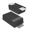
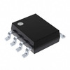
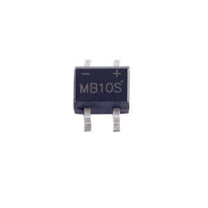
TheMB10S bridge rectifier, known for its compact and efficient design, is encased in an SOIC-4 package. It adeptly handles surges up to 35A and voltages as high as 1000V. This rectifier comprises four diodes, seamlessly facilitating the transition between positive and negative poles, which simplifies the installation and connection process. Built with General Purpose Plastic (GPP) chip technology, it exhibits low leakage current and an impressive surge capacity of 30A. This makes it suitable for applications where space is limited but high performance is a craving that cannot be ignored.
Equivalent Replacements
• DB107
• KBL04
• MB1S
MB10S Bridge Rectifier Symbol, Footprint, and Pin Configuration
The MB10S rectifier bridge comprises four distinct pins:
Pin 1 functions as the positive output terminal. It provides a stable DC voltage, supporting the operation of various electronic devices. In real-world scenarios, the reliability of this connection enhances energy transfer effectiveness and reduces power dissipation, reflecting a deeper commitment to efficiency.
Pin 2 acts as the negative output terminal. Alongside Pin 1, it constructs the DC output necessary for converting AC input to useful DC power. The polarity here demands careful handling to safeguard connected components, echoing the meticulous nature of design.
Pins 3 and 4 serve as AC input terminals, accepting alternating current for rectification purposes. The way the input waveform is managed directly impacts the quality of output. Often, a well-balanced AC input can bolster system stability and performance.
MB10S Bridge Rectifier Specifications
|
Product Attribute |
Attribute Value |
|
Manufacturer |
onsemi |
|
Package / Case |
SOIC-4 |
|
Packaging |
Reel/Cut Tape/MouseReel |
|
Length |
4.95 mm |
|
Width |
4.2 mm |
|
Height |
2.7 mm |
|
Reverse Voltage |
1 kV |
|
Reverse Current |
5 uA |
|
Power Dissipation |
1.4 W |
|
Operating Temperature |
-55 °C ~ 150 °C |
|
Mounting Style |
SMD/SMT |
|
Termination Style |
Solder Pad |
|
Configuration |
Single |
|
Pin Count |
4 |
|
Product Type |
Bridge Rectifiers |
MB10S Bridge Rectifier Features
The MB10S incorporates sophisticated reverse polarity shielding. This mechanism safeguards devices by halting power flow if voltage levels are inverted, thereby providing a protective embrace to components. Such systems help avoid unexpected repairs and minimize the disruption of electronic operations.
Leveraging a four-diode design, the MB10S delivers impressive rectification efficiency. This configuration cuts down on energy waste, making it appealing for applications focused on power savings, like those in renewable energy sectors where efficiency is treasured.
The chip’s robustness in handling high voltage inputs enables integration into a variety of power settings, from low to high. Its use spans household gadgets to complex industrial machines, showcasing the kind of flexibility often seek when crafting adaptable systems.
The Operation of the MB10S Bridge Rectifier
Bridge rectifiers like the MB10S serve as important elements in electronic circuits, transforming alternating current (AC) into direct current (DC). Their structure includes four diodes, precisely configured to achieve this transformation.
In the positive half-cycle of the AC input, a diagonal pair of diodes becomes forward-biased, permitting current flow. This direct routing aids in refining the DC output, catering to the consistent energy transition.
Conversely, during the negative half-cycle, the opposing diagonal pair of diodes is activated. This alternation between conducting pairs maintains a steady stream of unidirectional current, nurturing a reliable DC output.
The Absolute Maximum Ratings for the MB10S Bridge Rectifier
|
Symbol |
Parameter |
Value |
Unit |
|
VRRM |
Maximum Repetitive Reverse Voltage |
1000 |
V |
|
VRMS |
Maximum RMS Bridge Input Voltage |
700 |
V |
|
VR |
DC Reverse Voltage (Rated VR) |
1000 |
V |
|
IF(AV) |
Average Rectified Forward Current at TA = 50°C |
||
|
On Glass-Epoxy PCB |
0.5 |
A | |
|
On Aluminum Substrate |
0.8 |
A | |
|
IFSM |
Non-Repetitive Peak Forward Surge Current |
||
|
8.3 ms Single Half-Sine-Wave |
35 | A | |
|
TSTG |
Storage Temperature Range |
-55 to +150 |
°C |
|
TJ |
Operating Junction Temperature Range |
-55 to +150 |
°C |
MB10S Bridge Rectifier Advantages and Disadvantages
Advantages
• Minimal leakage and surge handling provide exceptional stability. This reliability is use for applications needing consistent performance under varying conditions. In pressure-sensitive industries, such stability becomes a asset.
• Efficient power utilization reduces heat dissipation, enhancing longevity while minimizing maintenance. This efficiency can lower energy costs and extend operational life in energy-aware environments.
• Operates over a wide temperature range from -55°C to 150°C, ensuring functionality in diverse climates and industrial settings.
• High efficiency and notable power conversion capabilities optimize performance, especially where energy conservation is required. This efficiency can transform sustainable technology efforts focused on maximizing energy return on investment.
Disadvantages
• Prolonged recovery time can limit high-frequency performance, requiring careful planning in applications needing quick response. In high-speed tech environments, these limitations demand strategic adjustments to maintain overall system efficiency.
• Compact size often necessitates additional heat dissipation solutions due to substantial thermal output. Effective thermal management poses design and deployment challenges, emphasizing the need for innovative cooling strategies.
• Elevated costs may increase system expenses, affecting budget considerations and cost-benefit analyses. Balancing quality with affordability requires careful financial assessment, weighing long-term benefits against initial costs.
Quality Assessment Techniques for the MB10S Bridge Rectifier
To evaluate if the MB10S rectifier operates effectively, start with a multimeter in diode mode. Anticipated readings for forward voltage generally center around 0.7V, while reverse bias should produce roughly -0.7V. Variations outside these figures might indicate issues.
Testing resistance offers additional perspective on the rectifier's condition. In forward mode: Resistance should near zero, showing the diode conducts correctly. In reverse mode: Expect infinite resistance to affirm the diode's current blocking capacity.
Applications of the MB10S Bridge Rectifier
Power Supply Systems
The MB10S bridge rectifier, converting alternating current (AC) to direct current (DC) with efficiency.
Battery Chargers
Utilized in battery chargers, this component ensures a smooth DC output, a feature that often elicits both technical appreciation and consumer satisfaction, given its reliability in extending battery life.
LED Drivers
In LED drivers, the MB10S contributes to optimal performance by providing consistent power, a characteristic that quietly supports creative and practical lighting solutions.
Small Appliances
The rectifier is present in small appliances, where its infusion of stability and consistency incites confidence, motivating further reliance on these everyday devices.
Motor Controls
Within motor controls, the MB10S assists in delivering streamlined performance, fostering a sense of trust and dependability.
Frequently Asked Questions [FAQ]
1. What is the role of MB10S in modern applications?
The MB10S plays a role in converting AC to DC, finding its way into a variety of devices. These include switch-mode power supplies (SMPS), LED lighting systems, adapters, and even home appliances and telecommunication equipment. Its capability to convert power efficiently influences both device performance and lifespan, especially in an energy-conscious world. You may rely on its reliability to enhance product functionality.
2. What package types are available for the MB10S diode?
The diode is offered in single in-line (SIP) and dual in-line (DIP) packages, allowing flexibility to meet different circuitry demands. Selecting the right package can affect the assembly process and the overall robustness of an application. It weigh these aspects carefully to align the diode with project requirements, achieving a blend of durability and space efficiency.
3. What is the operating input voltage range of MB10S?
The MB10S handles currents of 0.5A across a 50 to 1000 volts range. This versatility aids its application in diverse settings where maintaining power stability is important. It effectively manages fluctuating voltages, ensuring consistent output for delicate components.
4. How does MB10F compare to MB10S?
While both MB10F and MB10S share similarities, the MB10F excels in heat dissipation due to its lower thermal resistance. This feature makes it preferable in environments with intense temperature management needs. You should prioritize such thermal nuances when selecting components for high-efficiency systems, highlighting the delicate balance between selection and system performance.
About us
ALLELCO LIMITED
Read more
Quick inquiry
Please send an inquiry, we will respond immediately.
TIP35C Transistor Overview and Applications
on September 30th
H1102N Pulse Ethernet Transformer: What It Is and How It Works?
on September 30th
Popular Posts
-

What is GND in the circuit?
on January 1th 2933
-

RJ-45 Connector Guide: RJ-45 Connector Color Codes, Wiring Schemes, R-J45 Applications, RJ-45 Datasheets
on January 1th 2488
-

Fiber Connector Types: SC Vs LC And LC Vs MTP
on January 1th 2080
-

Understanding Power Supply Voltages in Electronics VCC, VDD, VEE, VSS, and GND
on November 8th 1877
-

Comparison Between DB9 and RS232
on January 1th 1759
-

What Is An LR44 Battery?
Electricity, that ubiquitous force, quietly permeates every aspect of our daily lives, from trivial gadgets to life-threatening medical equipment, it plays a silent role. However, truly grasping this energy, especially how to store and efficiently output it, is no easy task. It is against this background that this article will focus on a type of coin cell battery that may seem insignificant on the...on January 1th 1709
-

Understanding the Fundamentals:Inductance Resistance, andCapacitance
In the intricate dance of electrical engineering, a trio of fundamental elements takes center stage: inductance, resistance, and capacitance. Each bears unique traits that dictate the dynamic rhythms of electronic circuits. Here, we embark on a journey to decipher the complexities of these components, to uncover their distinct roles and practical uses within the vast electrical orchestra. Inductan...on January 1th 1650
-

CR2430 Battery Comprehensive Guide: Specifications, Applications and Comparison to CR2032 Batteries
What is CR2430 battery ?Benefits of CR2430 BatteriesNormCR2430 Battery ApplicationsCR2430 EquivalentCR2430 VS CR2032Battery CR2430 SizeWhat to look for when buying the CR2430 and equivalentsData Sheet PDFFrequently Asked Questions Batteries are the heart of small electronic devices. Among the many types available, coin cells play a crucial role, commonly found in calculators, remote controls, and ...on January 1th 1537
-

What Is RF and Why Do We Use It?
Radio Frequency (RF) technology is a key part of modern wireless communication, enabling data transmission over long distances without physical connections. This article delves into the basics of RF, explaining how electromagnetic radiation (EMR) makes RF communication possible. We will explore the principles of EMR, the creation and control of RF signals, and their wide-ranging uses. The article ...on January 1th 1533
-

CR2450 vs CR2032: Can The Battery Be Used Instead?
Lithium manganese batteries do have some similarities with other lithium batteries. High energy density and long service life are the characteristics they have in common. This kind of battery has won the trust and favor of many consumers because of its unique safety. Expensive tech gadgets? Small appliances in our homes? Look around and you'll see them everywhere. Among these many lithium-manganes...on January 1th 1502


