DS1302: Pin Function, Principle of Operation and Usage
Catalog
DS1302 Overview
DS1302 is a high-performance, low-power real-time clock chip produced by the American DALLAS company. It has built-in 31 bytes of static RAM and communicates with the CPU through the SPI three-wire interface. This chip supports burst mode and can transmit multiple bytes of clock signals and RAM data at one time. The real-time clock function provides seconds, minutes, hours, day, week, month and year information. When the number of days in the month is less than 31 days, it can automatically adjust and has a leap year compensation function. DS1302 has a wide operating voltage range and can operate between 2.5 and 5.5V. It adopts a dual power supply system, including main power supply and backup power supply, and allows the charging method of the backup power supply to be set, thus having the ability to charge the backup power supply with trickle current.
Alternatives and equivalents:
• DS1302+
• DS1302N
• DS1302S
Characteristics of DS1302
DS1302 has the following key features:
Low power consumption design: The chip adopts a low power consumption design, so it can provide long running time when powered by battery.
Data retention function: DS1302 has a data retention function, which means that the clock and calendar data can still be maintained even when the power is cut off, thereby ensuring data reliability and continuity.
Simplified interface: DS1302 communicates with a microcontroller or other external devices through a serial interface (2-wire or 3-wire). This simplified interface makes it easier to integrate with other systems to implement real-time clock functionality.
Clock and calendar functions: DS1302 can track seconds, minutes, hours, date, month and year. It provides complete clock and calendar functions to accurately record time and date.
Clock accuracy: DS1302 uses a 32.768kHz crystal oscillator to provide a reference clock signal, so it has high clock accuracy. This allows it to provide accurate time information with very small monthly deviations.
Pin Functions and Structure of DS1302
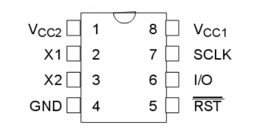
In the pinout of DS1302, VCC1 is the backup power supply, while VCC2 is the main power supply. The DS1302 ensures continuous clock operation even when the main power supply is turned off. This chip will automatically select the power supply method based on the voltage between VCC1 and VCC2: when the voltage of VCC2 is greater than VCC1+0.2V, DS1302 is powered by VCC2; when the voltage of VCC2 is less than VCC1, it is powered by VCC1. X1 and X2 are oscillation sources for external 32.768kHz crystal oscillator. RST is the reset/chip select line. When RST is set high, it will start all data transfers. The functions of RST mainly include two points: one is the control logic, which allows the address/command sequence to be sent into the shift register; the other is to provide a means to terminate single-byte or multi-byte data transfer. During the data transfer process, if RST is set to low level, then the data transfer will be terminated and the I/O pin will become a high impedance state. During power-on operation, in order to ensure that the chip works normally, we must keep RST low before the VCC voltage reaches 2.5V. At the same time, RST can be set high only when SCLK is low. I/O is the input and output terminal of serial data (bidirectional). The specific working method will be explained in detail later. SCLK is always the input terminal and is used for synchronous data transmission.
Precautions for Using DS1302
• Excitation clock frequency: The excitation clock frequency of DS1302 should be below 100kHz to avoid affecting its normal operation.
• Voltage stabilization: DS1302 is also sensitive to the voltage stability of the input power supply, so an appropriate voltage stabilizing circuit needs to be added to the system.
• Temperature: The temperature working range of DS1302 is set between 0°C and 70°C. If the working environment temperature exceeds this range, it may have adverse effects on the normal operation of DS1302.
• Power supply range: The normal operating voltage range of DS1302 is between 2V and 5.5V. If the voltage exceeds this range, it may cause chip damage or long-term operation instability.
• Load capacity: The load current capacity of the DS1302 output signal is limited. If the external LED lights and other equipment have a large load, their normal operation may be affected.
• Anti-static: Since DS1302 is usually in an electrostatic environment, we need to take corresponding measures to prevent it from being interfered by static electricity. For example, before use, we need to connect the ground wire and wear appropriate anti-static gloves and other equipment.
Introduction to the Clock Register of DS1302
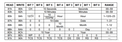
• Register 0: The highest bit CH is a clock stop flag. It is 1 after stopping and 0 when working normally. If VCC1 is floating or the battery is dead, when we power on again next time, read this bit, then this bit will be 1. We can use this bit to determine whether the clock is still running normally after the microcontroller system is powered off. The remaining 7 high-order digits are the tens digits of the second, and the low-order 4 digits are the ones digits of the second.
• Register 1: The highest bit is unused. The upper 3 bits of the remaining 7 bits are the tens digit of the minute, and the lower 4 bits are the ones digit of the minute.
• Register 2: If bit7 is 1, it represents the 12-hour format, and 0 represents the 24-hour format; bit6 is fixed to 0, and bit5 represents the morning in the 12-hour format, and 1 represents the afternoon. In the 24-hour format, it is the same as bit4. Together they represent the tens digit of the hour, and the lower 4 digits represent the ones digit of the hour.
• Register 3: The high 2 bits are fixed to 0, bit5 and bit4 are the tens digits of the date, and the low 4 bits are the units digits of the date.
• Register 4: The high 3 bits are fixed to 0, bit4 is the tens digit of the month, and the low 4 bits are the ones digit of the month.
• Register 5: The upper 5 bits are fixed to 0, and the lower 3 bits represent the day of the week.
• Register 6: The high 4 bits represent the tens digit of the year, and the low 4 bits represent the ones digit of the year. Please pay special attention that 00 to 99 here refers to the years 2000 to 2099.
• Register 7: The highest bit is a write protection bit. If this bit is 1, writing data to any other register or the 31-byte RAM is prohibited. Therefore, this bit must be written to 0 before writing data.
How Does DS1302 Work?
DS1302 is a real-time clock chip whose working principle is mainly based on the combination of oscillator and frequency divider. The chip has a built-in 32.768kHz oscillator, which generates a stable frequency signal through the oscillation of the crystal. This frequency signal is then divided by a frequency divider into a 1Hz time reference pulse. When starting work, DS1302 initializes its internal registers through the power-on reset circuit. Afterwards, the DS1302 uses a latch to latch the 1Hz pulse output from the oscillator into the internal count register. These counting registers store the current time information in BCD (Binary Coded Decimal) form, including year, month, day, hour, minute, and second. In addition, DS1302 also has write protection function. It can be put into read-only mode by setting the corresponding control register bit, thus preventing accidental operation or malicious changes. For data reliability, DS1302 stores the data in the counting register in the internal SRAM (static random access memory). In the event of a power outage, the DS1302 automatically switches to battery backup mode to maintain persistent storage of data. When external power is reconnected, the DS1302 recovers the data from the SRAM and reloads it into the counting register via the latch, ensuring continuity and accuracy of the clock function.
Reference Circuit of DS1302
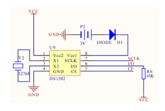
The basic circuit of DS1302 is shown in the figure above. Among them, Y2 is a 32.768kHz external crystal oscillator, which provides a stable clock source for the chip; P2 is a backup battery, ensuring that the chip can continue to run after the main power supply is powered off; D1 is a diode, which plays a one-way conduction role, effectively preventing the main power supply voltage from being too high and damaging the backup battery; R6 serves as a pull-up resistor, which can enhance the stability of signal transmission.
How to Use DS1302?
The steps to use the DS1302 are as follows:
Hardware connection: Connect the DS1302 chip to the main controller. DS1302 needs to be connected to VCC (3.3V or 5V power supply), GND (ground), and the data line (DIO), clock line (SCLK) and reset line (RST) of the master controller.
Clock setting: In normal working mode, write the corresponding year, month, day, hour, minute and second data to DS1302 to set the clock. DS
Frequently Asked Questions [FAQ]
1. What is DS1302?
The DS1302 is an accurate clock module which contains a real-time clock/calendar and 31 bytes of static RAM. Communication with the host microcontroller is through the serial I2C interface.
2. What is the difference between DS1307 and DS1302?
The DS1302 communicates via a special 3-wire interface using the three pins SCLK, I/O (DAT) and CE (RST). The DS1307 communicates via I2C and therefore only requires SDA and SCL.
3. What is the supply voltage of DS1302?
The DS1302 chip is very power efficient and can run on the 3V lithium battery for up to 5 years. The supply voltage is 5V. RTC module uses the serial I2C communication protocol, which makes the interfacing of this module with the microcontroller very easy.
4. What is the function of DS1302 RTC module?
This RTC DS1302 Real Time Clock Module allows you to use your Arduino or MCU to do time / date related functions such as: Starting a task at a specific date / time or recording the date / time of an event or simply displaying the time / date to a user.