What Are Seven-Segment LED Displays? Understanding the Technology Behind the Numbers
A seven-segment display (SSD) is a type of electronic screen used to show numbers and some letters. It first appeared in the early 1900s and became popular because it’s simple and works well. LED-based seven-segment displays are widely used because they are bright and easy to see. They come in different sizes, from tiny ones in handheld gadgets to big panels that can be seen from far away in different lighting conditions. This article looks at the details and types of seven-segment displays, including their parts, how they work, and their advantages over other displays like LCDs. It also explains the differences between common anode and cathode and how these suit different electronic needs. The article further explores how nine, fourteen, and sixteen-segment displays improve character recognition and expand their uses.Catalog
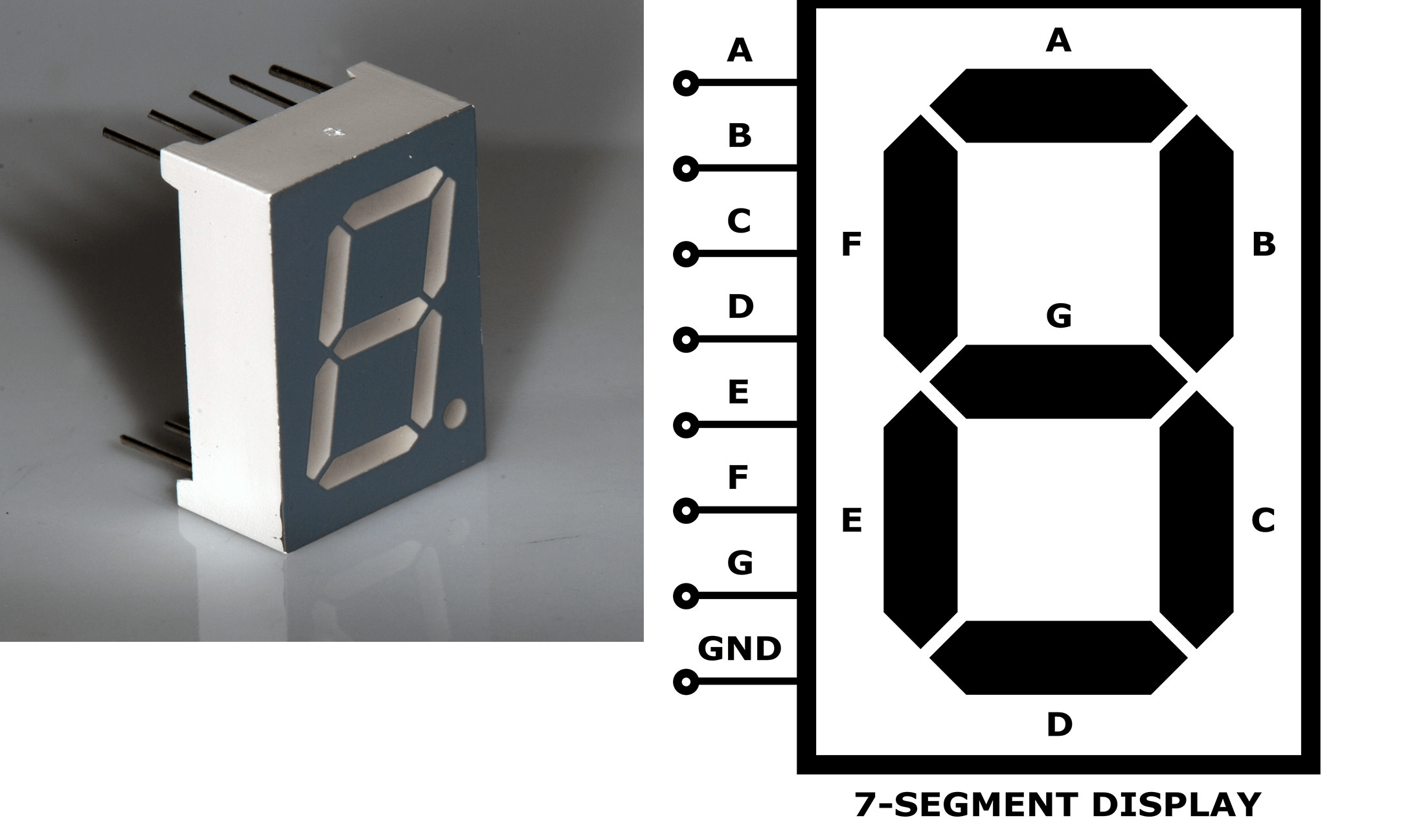
Figure 1: Seven-Segment LED Display
Structure of a Seven-Segment LED
A seven-segment LED display consists of eight parts: seven segments labeled from 'a' to 'g', and a decimal point (DP). Each segment is a small LED configured to form parts of numerals and some letters when illuminated in combination. Here is a detailed look at each segment and its function:
Segment 'a':
This horizontal segment is located at the top of the display. It lights up to form the top part of numerals and letters such as 0, 2, 3, 5, 6, 7, 8, 9, A, E, and F.
Segment 'b':
Found on the upper right side, this vertical segment is good for forming the right part of many numerals and letters. It appears in 0, 1, 2, 3, 4, 7, 8, 9, A, B, D, and E.
Segment 'c':
Located on the lower right side, this vertical segment works with segment 'b' to complete the right side of characters. It is used in 0, 1, 3, 4, 5, 6, 7, 8, 9, and A, D.
Segment 'd':
This horizontal segment is at the bottom of the display. It forms the base of most numbers and some letters, lighting up in 0, 2, 3, 5, 6, 8, 9, A, D, E, and G.
Segment 'e':
Found on the lower left side, this vertical segment helps form the left lower part of characters. It lights up in 0, 2, 6, 8, E, and F.
Segment 'f':
Located on the upper left side, this vertical segment pairs with segment 'e' to complete the left side of characters. It is active in 0, 4, 5, 6, 8, 9, E, and F.
Segment 'g':
This middle horizontal segment crosses the display. It adds strokes to form numbers and letters effectively, appearing in 2, 3, 4, 5, 6, 8, 9, A, E, and G.
Decimal Point (DP):
Positioned to the lower right of the segments and the decimal point is used to display decimal values. This enhances the display's ability to show precise numerical values like monetary amounts or measurements.
Each segment can be controlled individually or in combination to represent a wide array of numerical and some alphabetical data. This makes the seven-segment display best for simple digital readouts.
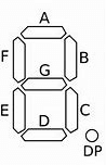
Figure 2: Seven-Segment LED Display Parts
Comparison of LED Displays and LCDs
Power Use and Efficiency
LED Displays: Use more power because they emit light directly from diodes. They are very visible, even in bright places.
LCDs: Use less power since they don’t emit light directly. They need backlighting or a reflective surface, making them more energy-efficient and good for battery-powered devices.
Visibility and Brightness
LED Displays: Very bright and clear, good for outdoor and well-lit areas. They stay clear from different angles without losing quality.
• LCDs: Modern ones are better with visibility and brightness due to improved backlights and color, but they often have limited viewing angles and lower brightness compared to LEDs.
Cost
LED Displays: Simple design, easier and cheaper to make for showing limited numbers and characters.
LCDs: More complex with extra layers and parts like filters and liquid crystal cells. This makes them more expensive but able to show detailed images and texts.
Lifespan
LED Displays: Durable and long-lasting, can handle tough conditions. Less affected by things like temperature and humidity.
LCDs: Durable but can have issues in extreme temperatures and might suffer from image retention or "burn-in" over time.
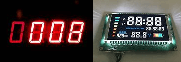
Figure 3: LED Displays and LCDs
Types of Seven-Segment Displays
Common Anode
In a common anode setup, the anodes of all the LEDs (or diodes) are connected to a shared point usually the positive voltage supply. Each LED or diode's cathode is then connected to the control circuit or ground through a resistor individually. To illuminate a specific LED, you apply a low voltage (near ground) to its cathode. Applying a higher voltage (near the positive supply) to the cathode turns the LED off.
How It Works?
When using a common anode display with a microcontroller, the individual segments light up by grounding their respective cathodes. The microcontroller sends a low signal (0V or ground) to the cathode of the segment to be illuminated. This allows current to flow from the common anode through the segment to ground, lighting it up. To turn off a segment, the microcontroller sends a high signal (close to the supply voltage) and stopping the current flow and keeping the segment dark.
In a common anode seven-segment display, all the anode connections of the LED segments are connected to a single common pin and then linked to the positive voltage supply (logic "1"). As a result, all the anodes are at a high potential. To illuminate a particular segment, a low voltage (logic "0") is applied to its cathode and grounding it. This completes the circuit between the high potential at the anode and the low potential at the cathode causing the segment to light up.
Advantages
Anode displays work well with positive logic circuits where a high output (logic 1) means the segment is off, and a low output (logic 0) means the segment is on. Also, this is simple for many digital designers. With the anode connected to a single positive supply point, the wiring is straightforward and reducing overall circuit complexity.
Disadvantages
The microcontroller or driver circuit must source current to light up the segments that can be difficult for low-power applications or controllers with limited current sourcing capabilities.
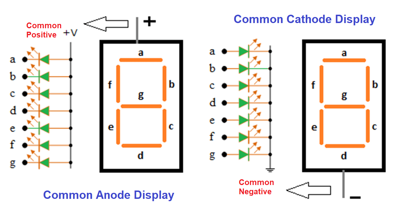
Figure 4: Common Anode and Common Cathode
Common Cathode
A common cathode configuration connects the cathodes of all the LEDs to a shared point and linked to the ground or negative voltage supply. The anodes are connected to the positive supply through individual resistors. To light up an LED, you apply a high voltage (near the positive supply) to its anode. Lowering the anode voltage to near ground level turns the LED off.
How It Works?
When using a common cathode display with a microcontroller, the individual segments light up by applying a high signal to their respective anodes. The microcontroller sends a high signal (close to the supply voltage) to the anode of the segment to be illuminated. This allows current to flow from the anode through the segment to the common cathode (ground), lighting it up. To turn off a segment, the microcontroller sends a low signal, stopping the current flow and keeping the segment dark.
In a common cathode seven-segment display, all the cathode connections of the LED segments are tied to a common pin connected to the ground or zero voltage level (logic "0"). In this configuration, the cathodes are at a low potential. To light up a segment, a high voltage (logic "1") is applied to its anode, raising its potential relative to the cathode. This higher potential at the anode relative to the cathode allows the segment to light up.
Advantages
Common cathode displays work well with negative logic circuits where a high output (logic 1) means the segment is on, and a low output (logic 0) means the segment is off. Furthermore, the microcontroller or driver circuit needs to sink current to light up the segments and often more efficient and manageable for many controllers, especially those designed with high current sinking capabilities.
Disadvantages
The common cathode requires more wiring connections, as each segment's anode must be individually connected to the control circuitry, making the circuit design more complex.
Differences Between Common Anode and Common Cathode Displays
|
Aspect |
Common Anode Displays |
Common Cathode Displays |
|
Driving Logic |
Segments activated by pulling the cathode
to ground (logic "0"). |
Segments activated by driving the anode
high (logic "1"). |
|
Compatibility with Logic Families |
Best with logic families that source
current (high logic level). |
Best with logic families that sink
current (low logic level). |
|
Circuit Design and Complexity |
Can be more complex to interface with
microcontrollers. |
Easier to interface with microcontrollers
that output high voltage for logic "1". |
|
Availability and Choice of Drivers |
Some drivers are optimized for common
anode configuration. |
Some drivers are optimized for common
cathode configuration. |
|
Power Consumption |
Voltage management can affect power
consumption at different brightness levels and during multiplexing. |
|
How Do Seven-Segment Displays Work?
Seven-segment displays work by lighting up LEDs. An LED lights up when its anode is at a higher voltage than its cathode. The brightness depends on the current through it, regulated by a driver circuit to ensure optimal visibility without overloading the LEDs.
Controlling segments involves turning them on or off by sending signals. Signals can be sent manually or digitally via a microcontroller or a driver IC like the 4511 BCD-to-seven-segment decoder/driver, which converts binary coded decimal (BCD) input into the corresponding signals to control the segments.
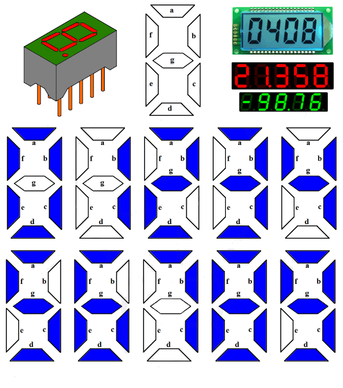
Figure 5: Seven-Segment Displays
Truth Table
A truth table shows which segments to light up for each character. Here’s an example for digits 0 through 9 and some letters (A, b, C, d, E, F):
|
Character |
A |
B |
C |
D |
E |
F |
G |
DP |
|
0 |
1 |
1 |
1 |
1 |
1 |
1 |
0 |
0 |
|
1 |
0 |
1 |
1 |
0 |
0 |
0 |
0 |
0 |
|
2 |
1 |
1 |
0 |
1 |
1 |
0 |
1 |
0 |
|
3 |
1 |
1 |
1 |
1 |
0 |
0 |
1 |
0 |
|
4 |
0 |
1 |
1 |
0 |
0 |
1 |
1 |
0 |
|
5 |
1 |
0 |
1 |
1 |
0 |
1 |
1 |
0 |
|
6 |
1 |
0 |
1 |
1 |
1 |
1 |
1 |
0 |
|
7 |
1 |
1 |
1 |
0 |
0 |
0 |
0 |
0 |
|
8 |
1 |
1 |
1 |
1 |
1 |
1 |
1 |
0 |
|
9 |
1 |
1 |
1 |
1 |
0 |
1 |
1 |
0 |
|
A |
1 |
1 |
1 |
0 |
1 |
1 |
1 |
0 |
|
b |
0 |
0 |
1 |
1 |
1 |
1 |
1 |
0 |
|
C |
1 |
0 |
0 |
1 |
1 |
1 |
0 |
0 |
|
d |
0 |
1 |
1 |
1 |
1 |
0 |
1 |
0 |
|
E |
1 |
0 |
0 |
1 |
1 |
1 |
1 |
0 |
|
F |
1 |
0 |
0 |
0 |
1 |
1 |
1 |
0 |
How to Use This Table for Programming Seven-Segment Displays?
Each column under a segment (A to G and DP for Decimal Point) shows the state needed for that segment to display the character.
• "1" means the segment is on (illuminated).
• "0" means the segment is off.
Store Values
• Store these values in a byte or an array of boolean values.
• Each bit or boolean represents a segment.
Example - Displaying "5"
• Find the row for "5" in the table.
• Set segments A, C, D, F, and G to 1.
• Set segments B, E, and DP to 0.
Send Data to Display
• Use direct GPIO pin control on a microcontroller.
• Alternatively, use a driver IC that interprets the signals and outputs the correct voltages to the segments.
Looking at the right row and setting the segments as indicated, you can program the display to show different characters.
How the 4511 Driver Works with Seven-Segment Displays?
The 4511 driver is a chip that helps show numbers on seven-segment displays. It converts binary-coded decimal (BCD) input into signals that light up the right segments on the display. This chip works well with common cathode displays, where all segment cathodes are connected to the ground.
When in use, the 4511 driver gets a four-bit BCD input, stands for a decimal number from 0 to 9. Each bit can be either high (1) or low (0). The driver reads this input and lights up the correct segments on the display. For example, to show the number 5, the BCD input is 0101. The driver then lights up segments a, c, d, f, and g. Inside the driver, logic gates decode the BCD input to control each segment. The outputs provide the needed voltage levels to light up the segments in a common cathode setup, where a high output turns on a segment.
Connecting a 4511 driver to microcontrollers makes seven-segment displays more functional and automated in digital systems. Microcontrollers can send BCD values through their digital I/O pins to the 4511 driver, then shows the corresponding number. This setup is useful for systems with multiple numeric displays needing simultaneous control. The microcontroller can update display values based on sensor data, user inputs, or internal calculations.
To integrate the driver with a microcontroller, connect the BCD output pins of the microcontroller to the BCD input pins of the 4511 driver. Other connections may control the display enable or disable function and the decimal point, depending on the application. In a digital clock, a microcontroller can send time data to several 4511 drivers to show hours, minutes, and seconds. Microcontrollers can work with other control devices like switches, keypads, or network interfaces, making complex user interfaces that use seven-segment displays.
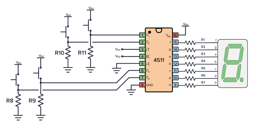
Figure 6: 4511 Driver Works with Seven-Segment Displays
Applications of Seven-Segment Displays
Digital Clocks: Show the time with high visibility.
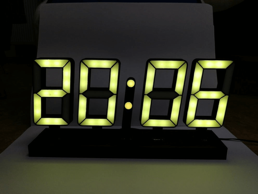
Figure 7: Seven-Segment Display Clock
Household Appliances: Used in microwaves and ovens to display cooking times and temperatures for convenient and efficient.
Automotive Industry: Used in car dashboards for speedometers and fuel gauges for quick and clear readouts.
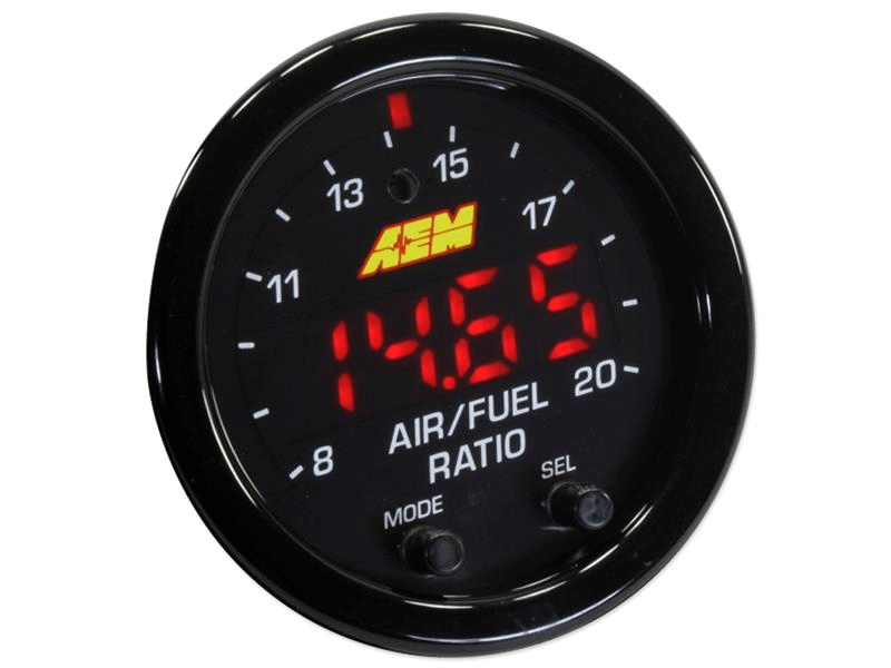
Figure 8: Seven-Segment Display Speedometers and Fuel Gauges
Public Information Displays: Common in elevators and public transport platforms, displaying numbers or simple messages in a format everyone can understand.
Gaming and Entertainment: Pinball and slot machines use them to display scores and game information dynamically.
Industrial Control Panels: Preferred in tough environments to show readings like temperatures and pressures because they are durable and easy to connect with electronic circuits.
Role of These Displays in the Internet of Things (IoT)
Seven-segment displays are important in the design of interfaces for many smart devices in the Internet of Things (IoT).
Firstly, perfect for small, battery-powered, or energy-saving systems used in IoT applications.
Then, provides clear status outputs or temperature settings in smart home devices like thermostats and security systems, making user interaction simple and inexpensive.
Next, easy to integrate with sensors and microcontrollers used in IoT devices.
Finally, used for applications like smart meters and other monitoring devices, especially in remote or hard-to-reach areas, providing immediate visual feedback to alert users of changes or problems.
Advantages and Limitations
Simplicity and Ease of Use
Seven-segment displays are easy to use because they show numbers and a few characters directly. They don't need complex programming or extra software and perfect for systems that need basic numeric displays.
Cost-Effectiveness
These displays are cheaper compared to advanced display technologies. They use fewer components and simpler control mechanisms, reduces the overall cost of the device.
High Visibility
The design ensures readability even in low light conditions. Each segment emits bright, distinct light, providing high contrast against the background and enhances visibility.
Durability
Made from sturdy materials, seven-segment displays can handle temperature variations and physical stress.
Limited Functionality
The main drawback is their limited functionality. They can only display numbers and a few characters, making them unsuitable for applications needing text or complex graphics.
Restricted Viewing Angles
These displays often have limited viewing angles, a disadvantage in situations where information must be visible from different perspectives, such as outdoor or large-area applications.
Higher Power Consumption
Seven-segment displays use more power than other types, like LCDs. Each lit segment needs continuous power and less ideal for battery-operated or power-sensitive applications.
Limited Customization
The design and functionality are fixed that restricts them to standard digits and characters. This lack of flexibility can be a problem in applications requiring more customization.
Extended Varieties of Segmented Displays
Nine Segment Displays
The nine-segment display builds on the standard seven-segment model by adding two diagonal segments, placed at the upper and lower parts of the display. These displays gained popularity in the 1970s, especially in calculators, digital watches, and early electronic devices.
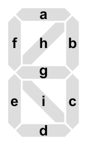
Figure 9: Nine-Segment Display
Fourteen Segment Displays
The fourteen-segment display, often called a "Union Jack" display due to its resemblance to the British flag when all segments are lit, expands the seven-segment structure with four diagonal segments, two vertical ones, and a split middle horizontal segment. This intricate design allows for a wider range of symbols and letters, greatly improving the display's ability to convey information. These displays are commonly used in entertainment and household devices like pinball machines, slot machines, VCRs, microwave ovens, and calculators.
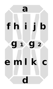
Figure 10: Fourteen-Segment Display
Sixteen Segment Displays
The sixteen-segment display goes a step further than the fourteen-segment version by splitting the top and bottom horizontal segments into two additional segments. This layout offers even greater flexibility in character representation and allowing for the display of complex symbols and enhancing alphanumeric visibility. Sixteen-segment displays are often used in car stereos, telephone Caller ID displays and other multimedia interfaces that require detailed character display.
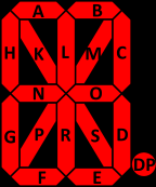
Figure 11: Sixteen Segment Displays
This table outlines different types of segmented displays and their features:
|
Display Type |
Description |
|
Nine-segment displays |
Better character differentiation than
seven-segment. |
|
Fourteen-segment displays |
More characters and used in consumer
electronics. |
|
Sixteen-segment displays |
Most detailed and distinguishes similar
characters. |
Conclusion
Examining seven-segment displays and their advanced versions shows their importance in digital displays. Even with newer technologies, seven-segment displays are still valuable because they are simple, cheap, and reliable. This article covers their basic structure, how they work, and compares them to LCDs. The discussion about their use in the Internet of Things (IoT) and various industries highlights their flexibility and lasting importance. The move from seven-segment to sixteen-segment displays shows the ongoing effort for better functionality and visual communication. In the end, seven-segment displays prove that basic engineering solutions can support complex systems, balancing old methods with new ideas in the digital world.
Frequently Asked Questions [FAQ]
1. Why is it called a 7-segment display?
A 7-segment display gets its name from having seven light segments that can be turned on or off in different patterns to show numbers and some letters. These segments are arranged in a pattern similar to a figure-eight.
2. How do you control a 7 segment LED display?
You control a 7-segment LED display by sending electrical signals to the segments you want to light up. This is usually done with a microcontroller or a digital circuit that sends high or low voltage signals to each segment’s control pin, turning them on or off as needed.
3. How to know if 7-segment is cathode or anode?
To find out if a 7-segment display is common cathode or common anode, check the wiring or datasheet. In a common cathode display, all the negative sides (cathodes) are connected together, and you light up segments by applying positive voltage. In a common anode display, all the positive sides (anodes) are connected, and you light up segments by applying ground or low voltage.
4. How to check the working of a seven-segment display?
To check if a seven-segment display works, apply power to each segment one by one and see if they light up. Use a power source with the right resistors, connecting it to each segment’s pin while the common pin (cathode or anode) is connected to ground or power, respectively. If each segment lights up, the display is working.
5. How do you test a 7-segment display with a multimeter?
To test a 7-segment display with a multimeter, set it to diode test mode. Connect the common pin (anode or cathode) to the corresponding multimeter lead (positive for anode, negative for cathode). Touch the other lead to each segment pin. A working segment will show a voltage drop on the multimeter (around 1.7 to 2.0 volts for LEDs). If there's no voltage drop, the segment might be faulty.
6. How many pins are there on a seven segment LED?
A basic single seven-segment display has 10 pins—seven for each segment, one for the decimal point, and two for the common connections (either cathode or anode). The number of pins can vary with dual displays or additional features.