Voltage Regulators: Their Function and Importance Explained
A voltage regulator is a device that keeps the voltage steady on its own. It adjusts the voltage to make sure the devices connected to it get a stable and consistent amount, even if the input voltage changes or the load conditions vary. This helps protect delicate electronic parts from getting damaged by voltage changes. This article takes a closer look at the main parts and types of voltage regulators, showing why they are so important for keeping electronics running smoothly. Breaking down the two main types of voltage regulators, describing how they work, their benefits, and what situations they’re best suited for. There's also a hands-on tutorial on building a voltage regulator on a breadboard, giving a practical way to learn about their design and function. Finally, it offers tips on how to choose the right voltage regulator, focusing on the balance between efficiency, heat control, and voltage stability for specific projects.Catalog
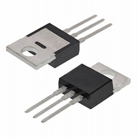
Figure 1: Voltage Regulator
Components of a Voltage Regulator
• Comparator
The comparator compares the output voltage to a set reference voltage. Its job is to ensure the output stays within a desired range by sending control signals that adjust the voltage accordingly. When the output drifts from the reference value, the comparator triggers adjustments to bring the output back in line.
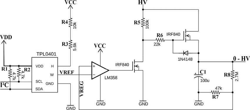
Figure 2: Voltage Regulator Circuit with Voltage Comparator
• Reference Voltage Source
This is a highly stable voltage that acts as the benchmark for comparison. The reference voltage stays constant, even if there are changes in input voltage, temperature, or load. This is provided by a bandgap reference, and offers reliable stability across different operating conditions.
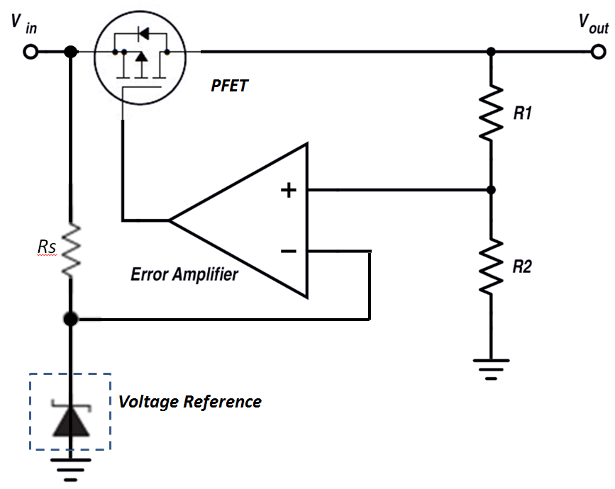
Figure 3: Reference Voltage Source
• Error Amplifier
The error amplifier magnifies the difference between the reference voltage and the output voltage. This amplified signal is then used to fine-tune the control mechanism, reducing the gap between the actual output and the target voltage. It ensures the output matches the intended voltage as closely as possible.
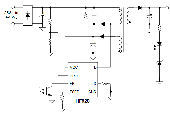
Figure 4: Voltage Regulator with Error Amplifier
• Feedback Network
The feedback network consists of resistors, and sometimes capacitors, that send a portion of the output voltage back into the system for monitoring. This feedback loop is important for setting the correct output voltage and stabilizing the regulator. The feedback ratio, determined by the network components, controls how much of the output is fed back to the error amplifier or comparator.
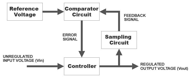
Figure 5: Feedback Signal in Voltage Regulator
• Control Element
The control element actively adjusts the output voltage. In linear regulators, this is a transistor working in its active state to regulate voltage. In switching regulators, the control element acts as a switch, turning the input voltage on and off to transfer energy through components like inductors or capacitors, smooth out the output.
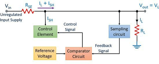
Figure 6: Control Element in Voltage Regulator
• Load Regulation
Load regulation is the regulator's ability to keep the output voltage steady as the load changes. Strong load regulation means that the output remains constant, even if the amount of current the load draws fluctuates.
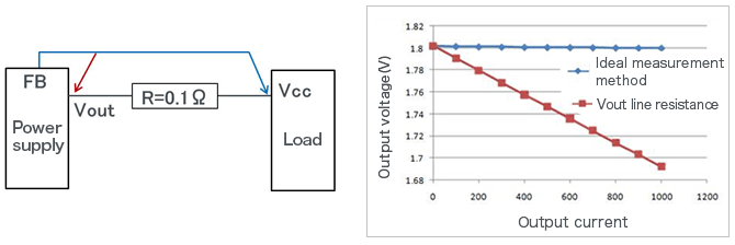
Figure 7: Load Regulation
• Line Regulation
Line regulation measures how well the regulator maintains a stable output when the input voltage varies. A good voltage regulator shows minimal output changes even when there are shifts in input voltage.
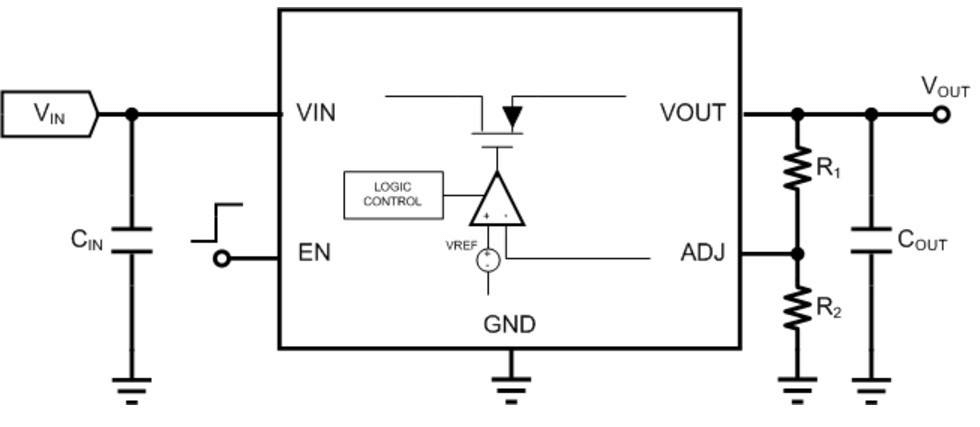
Figure 8: Line Regulation
• Heat Sink
For linear regulators that can generate heat by dissipating excess voltage, a heat sink is often required. It helps disperse the heat produced by the control element, such as a transistor, keeping the device within safe operating temperatures.
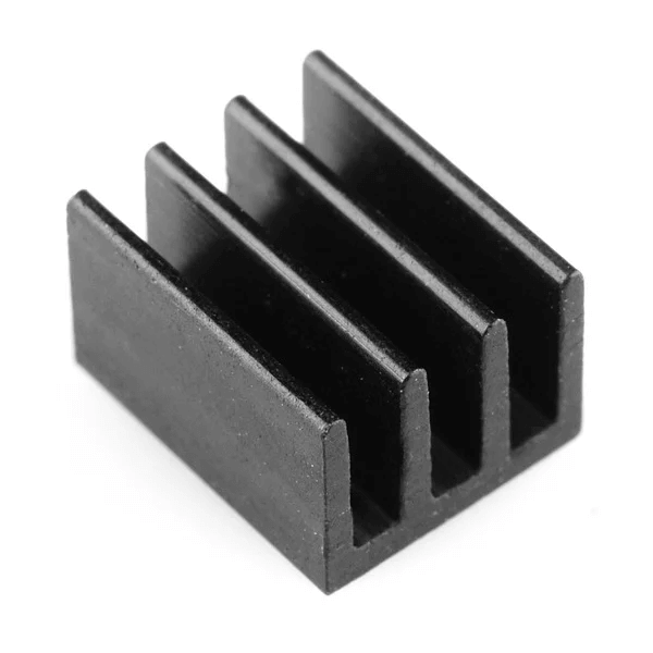
Figure 9: Heat Sink
• Protection Circuitry
Many voltage regulators come with built-in protection features like overcurrent, thermal shutdown, and short-circuit protection. These safeguards prevent the regulator and connected devices from being damaged, enhancing overall safety and reliability.
Types of Voltage Regulators
Linear Voltage Regulators
Linear voltage regulators use a main part called a pass element, usually a type of transistor like a Bipolar Junction Transistor (BJT) or a MOSFET. This part is controlled by an operational amplifier. To keep the voltage stable, the regulator constantly compares the output voltage with a fixed internal reference voltage. If the two are not the same, the operational amplifier changes the pass element to fix the output. This process keeps working to make the difference between the two voltages as small as possible.
Since linear regulators can only lower the voltage, the output will always be less than the input voltage. Even though this limits how they can be used, linear regulators are still popular because they are simple and perform well. They are easy to design, reliable, cost-effective and produce very little electromagnetic interference (EMI), means there’s less noise and ripple in the output.
For example, a simple linear regulator like the MP2018 only needs an input capacitor and an output capacitor to work properly. This small number of parts makes the design easy, reliable, and affordable.
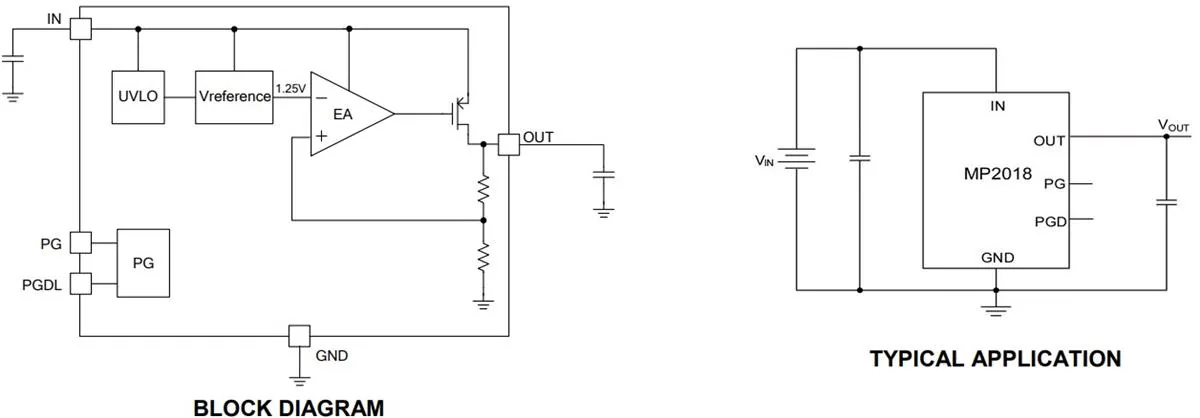
Figure 10: Linear Voltage Regulator
Switching Voltage Regulators
Switching regulators are a more advanced option compared to linear regulators, but their design requires more precision and attention to detail. Unlike linear regulators, switching regulators depend on external components, careful control loop tuning, and thoughtful layout planning. These regulators come in three main types: step-down (buck) converters, step-up (boost) converters, and a combination of the two. This range of options makes them far more flexible than linear regulators.
One of the advantages of switching regulators is their high efficiency, often surpassing 95%. They also excel at managing heat and are capable of handling larger currents while supporting a wide variety of input and output voltages. However, the trade-off for this performance is increased complexity. To work properly, switching regulators need extra components like inductors, capacitors, field-effect transistors (FETs), and feedback resistors.
A good example of a switching regulator is the HF920 model that demonstrates the strong performance and reliable power management these devices offer.
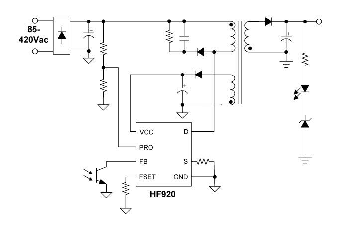
Figure 11: Switching Voltage Regulator
Types of Switching Voltage Regulators
Buck regulators, also called step-down converters, are used to reduce a higher voltage to a lower, more usable output voltage. The process begins with a transistor that switches on and off at high speed, chopping the input voltage into short bursts. These rapid bursts of voltage are then passed through an inductor that stores energy temporarily. As the voltage continues, it is further smoothed by a capacitor, resulting in a steady lower output voltage. This method is efficient, reducing energy wasted as heat. Buck regulators are good in devices like laptops, smartphones, and other portable electronics.
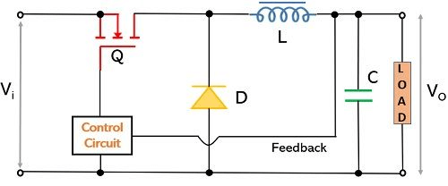
Figure 12: Circuit of Buck Regulator
Boost regulators, often referred to as step-up converters, work to increase a low input voltage to a higher output voltage. Here, a transistor charging an inductor when it’s active and releasing the stored energy when it switches off. This controlled release elevates the voltage level. These regulators are useful in situations where the input power, like that from a battery, is too low for the device’s needs. As batteries deplete, the boost regulator ensures the voltage remains consistent, keeping devices operational even as power levels drop. This makes them ideal for many battery-powered electronics that require a steady voltage despite fluctuating energy supply.
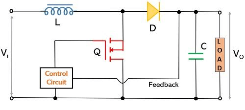
Figure 13: Circuit of Boost Regulator
Buck-boost regulators combine the features of both buck and boost converters, allowing them to either increase or decrease the input voltage as required. These regulators first invert the input voltage and then adjust it, either stepping it up or down depending on the required output. This ability to adapt to changing conditions makes buck-boost regulators great in systems with unpredictable or unstable input voltages, such as in cars or renewable energy applications like solar power systems. By providing a stable output regardless of input fluctuations, they ensure that connected devices perform reliably across a wide range of conditions.
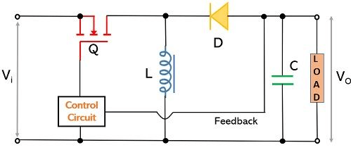
Figure 14: Circuit of Buck-Boost Regulator
Build Your Own Breadboard Voltage Regulator
The Breadboard Voltage Regulator Kit is the perfect entry point for beginners looking to get hands-on experience with soldering and basic circuit design. Not only will you learn the core concepts of electronics, but by the end of this project, you'll have built a fully functional device, capable of providing a steady 5VDC output for small electronics projects.
This kit includes everything you need to assemble a reliable voltage regulator:
- Printed Circuit Board (PCB)
- DC Power Jack
- Capacitors and Resistor
- Power Status LED
- Pin Headers
- Comprehensive Instruction Manual
The tools required for this project are:
- Soldering Iron and Solder
- Wire Cutters
- Power Supply (such as a 6-18V wall adapter)
The assembly process is broken down step-by-step to help you understand the operation of a voltage regulator as you go.
Step 1: Installing the Resistor and Capacitor
Start by picking up the resistor and bending its leads to fit into the R1 slot. Insert it into the designated spot on the board and solder the leads securely from the back. Once soldered, snip off any extra wire sticking out. Next, grab the 0.1µF capacitor and follow the same process for slot C2. There's no need to worry about which way they’re facing, these components can be placed in either direction because they aren’t polarized.
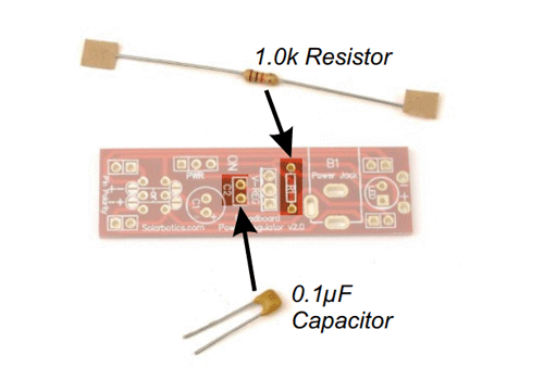
Figure 15: Installing the Resistor and Capacitor
Step 2: Setting Up the Voltage Regulator and Barrel Jack
Place the voltage regulator into the V-REG slot, make sure to align the tab with the line indicated on the board. Getting this orientation correct is important, if installed backward, the regulator won’t work and could damage the circuit. The regulator’s role is to keep the voltage steady even if the input fluctuates, ensuring the power delivered to your circuit stays stable. After soldering the leads, trim the extra wire. Now, move on to the barrel jack, insert it into slot B1 and solder it in place. This will serve as the main power connection for your project.
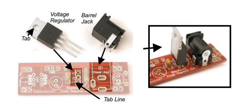
Figure 16: Setting Up the Voltage Regulator and Barrel Jack
Step 3: Placing the Capacitor and Power LED
Insert the 10µF capacitor into slot C1, making sure the longer lead goes into the (+) pad. Double-check that the stripe on the capacitor is next to the PWR label for proper orientation. Afterward, install the LED in its slot, aligning the notch with the corresponding line on the board’s symbol to ensure it’s placed correctly.
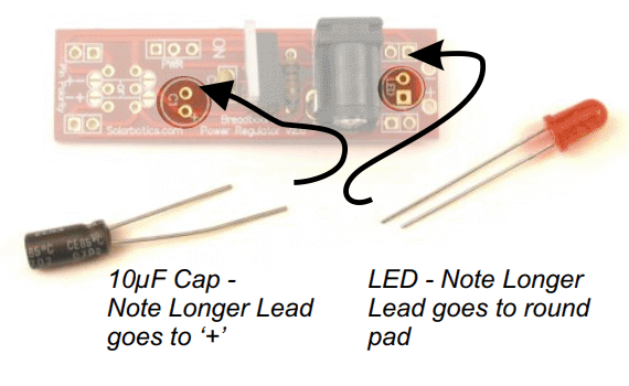
Figure 17: Placing the Capacitor and Power LED
Step 4: Installing the Power Switch and Breadboard Pins
Place the power switch into the PWR slot and solder it securely. When it comes to the breadboard pins, they can be tricky to manage because they need to be soldered from underneath. To keep them aligned, you can either hold them steady by hand as you solder or use a breadboard to support them during the process.
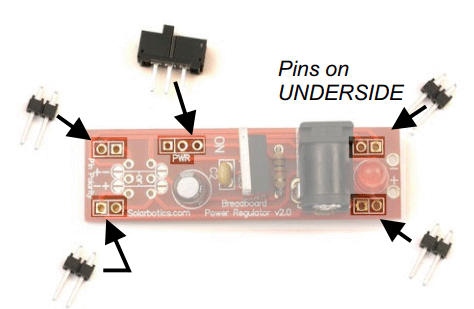
Figure 18: Installing the Power Switch and Breadboard Pins
Step 5: Configuring Power Rails
To ensure the voltage regulator works correctly, you need to set up the power rails. Choose the side of the breadboard you want to use. Let’s go with the left for this setup. Match the pads on the board to the ‘+’ and ‘-’ rails on the breadboard. Once everything is aligned, solder the half-moon pads to lock the connection in place. If you ever need to reverse the power polarity, you could use part number SWT7 on specific pads, although this is usually not advisable.
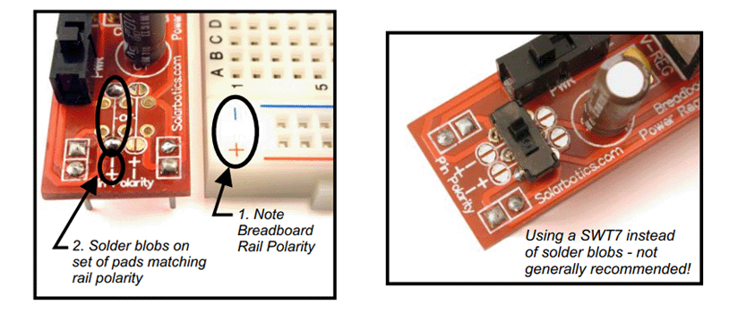
Figure 19: Configuring Power Rails
Step 6: Powering the Board
Use a 2.1mm DC power source that provides between 6 to 18 volts to power the board. If the input voltage goes above 12 volts, the regulator might get hot, but that's normal and not a cause for concern. If you’re not using a breadboard, you can use the “+ -” solder pads located near the barrel jack to draw 5V of regulated power.
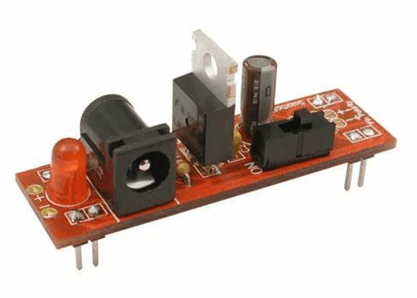
Figure 20: Breadboard Voltage Regulator Kit
How to Pick the Right Voltage Regulator for Your Design?
A voltage regulator is like a control system for your project's energy. It makes sure your project gets the right amount of power.
Imagine your power source gives more voltage than your project needs. A linear regulator is a simple device that lowers the voltage to a safe level for your project. It's easy to use and works well if the difference between the voltage you have and the voltage you need isn’t too big.
But linear regulators can waste energy, when there's a big difference between the input and output voltage. This wasted energy turns into heat and become a problem for your project.
If your linear regulator is getting too hot, it means it's wasting a lot of power. In this case, you might want to use a buck switching regulator. This type of regulator is more efficient and doesn’t waste as much energy. It lowers the voltage by turning the power on and off really fast to create an average lower voltage.
If your project needs more voltage than your power source can provide, a boost switching regulator can help. It increases the voltage from your power source to give your project the extra power it needs.
Sometimes, your power source may not be stable, giving too much or too little voltage. A buck-boost switching regulator can both increase and decrease the voltage as required, making sure your project always gets the right amount of power.
For projects that need very stable power, you can combine a switching regulator with a linear regulator. The switching regulator handles big changes in voltage, while the linear regulator ensures the power is smooth and steady.
So, the right voltage regulator depends on how much the voltage from your power source differs from what your project needs, and how steady and clean the power has to be. Each type has its own strengths, so choose the one that fits your project best.
Conclusion
The study of voltage regulators covers an important part of electrical engineering that combines practical use and theory. The article explains components like error amplifiers and heat sinks, as well as the differences between linear and switching regulators, giving a solid understanding of how these devices control power. It also includes a step-by-step guide on building a voltage regulator on a breadboard, which helps make the process clearer and gives readers hands-on experience to support the concepts. As electronic designs get more complicated and power needs change, knowing how voltage regulation works becomes very important. This article acts as both a teaching tool and a practical guide, helping both designers and hobbyists choose and use the best voltage regulators for their projects, ensuring their electronics last longer and work well.
Frequently Asked Questions [FAQ]
1. When to use a voltage regulator?
A voltage regulator is important when stable voltage is needed for electronic devices to work properly. It protects against damage from sudden voltage changes, which can happen due to shifts in power demand or supply issues. It is used in things like computer power supplies, telecom equipment, and other devices that are sensitive to voltage changes.
2. Is AVR a voltage regulator?
Yes, AVR (Automatic Voltage Regulator) is a type of voltage regulator. It automatically adjusts the voltage level to ensure that a constant and appropriate voltage is delivered to the equipment, regardless of changes in the load or input voltage. This helps in preventing damage and improving efficiency in electrical devices.
3. What is an AC voltage regulator?
An AC voltage regulator controls the voltage of alternating current (AC) power to provide a stable output voltage to connected devices. It compensates for variations in the input voltage and load conditions, ensuring the delivery of a constant AC output, good for the reliable operation of AC-powered devices.
4. Is an inverter a voltage regulator?
No, an inverter is not a voltage regulator. An inverter is designed to convert direct current (DC) into alternating current (AC). While some inverters have built-in capabilities to stabilize output voltage, their main function is the conversion of current type, not regulating voltage.
5. How do you test a voltage regulator?
Here’s how to test a voltage regulator:
Set Up the Multimeter: Set your multimeter to measure voltage.
Connect the Multimeter: Attach the probes to the regulator's output terminals.
Check the Voltage: Turn on the system and check the reading. It should match the regulator's expected output.
Optional: Test with Load: Change the load and see if the output stays steady, which shows the regulator is working correctly.
6. What is the difference between a voltage controller and a voltage regulator?
A voltage controller adjusts the output voltage based on user input, like changing light brightness or motor speed. A voltage regulator keeps the voltage steady, even if the load or input changes. Controllers change voltage as required, while regulators ensure it stays constant.