Understanding the Silicon-Controlled Rectifier (SCR)
The Silicon-Controlled Rectifier (SCR) is a key part of power electronics, evolving from the simpler Shockley diode. The Shockley diode acted as a basic switch but couldn't be controlled externally. Adding a gate terminal to create the SCR allowed precise control over its conduction, turning it into an active component for managing power in various circuits. This article covers the SCR's structure and operation, including its internal configuration and positive feedback mechanism for efficient switching. It explains different triggering methods and the need for controlled activation for reliable performance. The article also discusses testing SCR functionality, uses in AC power control, advanced triggering techniques, types of SCRs, and new trends in SCR technology. The goal is to give a clear understanding of SCRs, how they work, and their role in modern electronics.Catalog
Shockley Diode to SCR
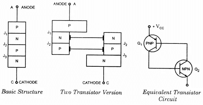
Figure 1: Shockley Diode
The Shockley diode, an early version of the PNPN device, works as a basic switch that turns on when it reaches a certain voltage. However, it has limited use because it lacks control over its switching. The introduction of the SCR improves on the Shockley diode by adding a gate terminal. This addition allows for external control of the device's conduction state, changing it from a simple switch to an active component that can handle higher power levels with greater accuracy. This change greatly increases the usefulness of the device, making it suitable for many more electronic circuits.
The Silicon-Controlled Rectifier Structure
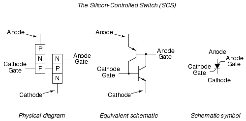
Figure 2: Silicon-Controlled Switch
The evolution from a Shockley diode to an SCR involves adding a gate terminal to the existing PNPN structure. This gate terminal allows the SCR to be controlled by an external signal, providing a way to switch the device on and off as needed. This change makes the SCR an active component, greatly expanding its use in various electronic circuits. The ability to control the switching action with an external signal creates new possibilities for precise power management, which is very useful for modern electronic applications.
Structure and Operation of an SCR
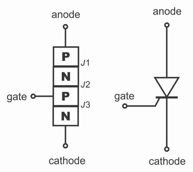
Figure 3: Structure And Operation of an SCR
An SCR is made up of four semiconductor layers that form three PN junctions, with an anode, a cathode, and a gate terminal. When the gate is left unconnected, the SCR acts like a Shockley diode, turning on when the breakover voltage is reached. However, applying a small voltage to the gate allows the SCR to be triggered on purpose.
SCR Conduction Path
When a small current is applied to the gate, the lower transistor in the SCR turns on. This action then turns on the upper transistor, creating a loop that keeps the SCR in the "on" state, allowing current to flow from the anode to the cathode. After this happens, the gate current is no longer needed to keep the SCR on. The SCR has two transistors working together to keep it on once it starts. This design helps the SCR switch quickly from off to on.
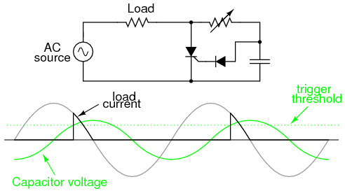
Figure 4: SCR Conduction Path
To understand how an SCR works, look at its internal setup. When a pulse is sent to the gate, it activates the lower transistor, letting current pass through the upper transistor and keeping the lower one on. This loop ensures the SCR stays on until the current drops below a certain level, called the holding current. This makes SCRs useful for switching and managing power reliably.
Triggering and Firing Methods
Triggering, also called firing, means applying a voltage pulse to the SCR's gate terminal. This method makes sure the SCR turns on only when needed, no matter if the voltage goes above the breakover point. Reverse triggering, which turns off the SCR by applying a negative voltage to the gate, can also be done but is less efficient because it requires a lot of current.
Gate Turn-Off Thyristor (GTO) Symbol
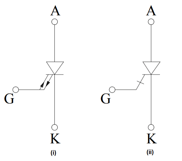
Figure 5: GTO Symbol
Triggering an SCR is key to its operation. The gate current needed to trigger an SCR is much lower than the current flowing through the device, providing some amplification. Once triggered, the SCR stays in the conducting state until the current through it falls below a certain level, known as the holding current. This characteristic is very useful in applications where controlled switching is needed, ensuring that the SCR stays on until the load current drops enough to turn it off. This controlled activation and deactivation make SCRs very suitable for applications that require precise power management.
Testing SCR Functionality
To test if an SCR works, you can start with a basic check using an ohmmeter to measure the gate-to-cathode junction. However, this simple test isn't enough. You also need to see how the SCR performs under load. For a thorough test, set up a circuit with a DC power source and pushbutton switches to observe how the SCR turns on and off when connected to a load.
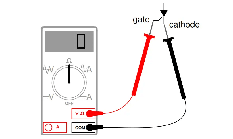
Figure 6: SCR Testing Circuit
To ensure SCRs work correctly, several steps are involved in their testing. A simple test circuit can be built using a DC power supply, a load resistor, and pushbutton switches to simulate the triggering and holding processes. By watching the SCR's behavior in this setup, one can confirm its ability to latch on and turn off as expected. This testing process helps diagnose potential issues and ensures the reliability of SCRs in real-world applications. Comprehensive testing under actual load conditions helps find any weaknesses or defects in the SCR, ensuring dependable performance in demanding applications.
SCR Control of AC Power
SCRs are often used where large amounts of power need to be switched, but the control circuits only handle small current and voltage for simplicity and reliability. This makes SCRs perfect for situations needing strong yet sensitive control mechanisms. For example, the gate firing power of an SCR can be as low as 50 microwatts (1 V, 50 µA), ensuring that the actuating contacts only manage this small signal. Once triggered, the SCR can handle and switch output loads directly, providing up to 100 watts or more. This allows for efficient control of high-power systems with minimal strain on the control circuitry.
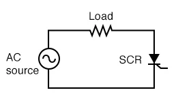
Figure 7: SCR In AC Power Control
In terms of how they work, the SCR's reverse behavior is like a typical silicon rectifier diode, acting as an open circuit when a negative voltage is applied between the anode and cathode. In the forward direction, the SCR blocks current flow until the voltage exceeds a specific breakover point, unless a gate signal is applied. When the forward breakover voltage is surpassed or an appropriate gate signal is introduced, the SCR quickly transitions to a conducting state, with a low forward voltage drop similar to that of a single-junction rectifier. This rapid switching ability ensures that the SCR can reliably manage high-power loads while maintaining a low power requirement for control operations.
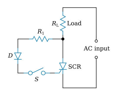
Figure 8: Series Switch
The figure above shows a simple series switch (S) that sends an AC signal to the SCR's gate. Resistor R1 limits the gate current to keep it safe, while diode D prevents reverse voltage from affecting the gate during the nonconducting cycle. The load (RL) connected to the anode can be any value within the SCR's limits. This setup ensures the SCR operates reliably, with controlled triggering and protection from electrical stress.
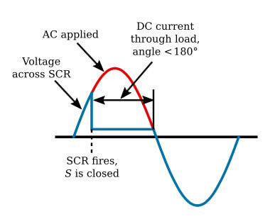
Figure 9: AC Switch Waveforms
When switch S is open, the SCR remains off even if AC power is present. Closing switch S allows the positive part of the AC cycle to trigger the SCR, causing it to conduct because the anode is positive. The SCR turns on for less than half the cycle and stays off during the negative part of the cycle. Closing S controls when the SCR turns on, allowing current to flow through the load. To stop the current, you can open switch S or wait for the negative cycle, which turns off the SCR. This setup allows easy control of the current flow in the circuit.
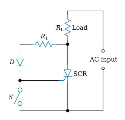
Figure 10: Shunt Switch
To control an SCR, you can use DC on the gate. Applying DC to the gate turns the SCR on. Another way is by using a switch (S) between the gate and cathode. Opening the switch turns the SCR on, allowing current to flow through the load. To turn off the SCR and stop the current, close the switch or apply a negative voltage to the anode. This method helps in controlling devices like motor speeds and power levels.
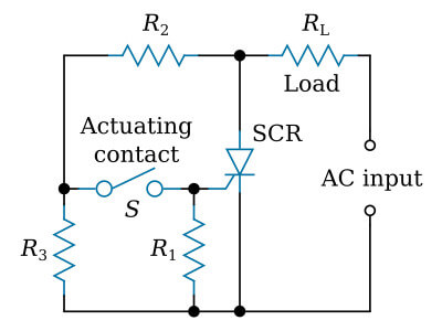
Figure 11: Load Current With Switch Closed
Two other simple methods for switching power to loads are illustrated. In the first circuit, closing the actuating contact supplies power to the load, while opening the contact cuts off the power. Conversely, the second circuit operates in reverse: power is supplied to the load only when the contact is open. Both circuits can be set up to "latch" using a DC supply instead of the AC shown.
In the first circuit, a voltage divider made up of resistors R2 and R3 provides the AC gate signal to the SCR. This allows the SCR to fire and supply power when the contact is closed. In the second circuit, closing the switch makes the gate and cathode have the same potential, preventing the SCR from firing and thus cutting off power to the load. This simple setup ensures clear and predictable control of power to the load in either configuration.
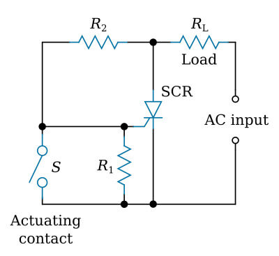
Figure 12: Load Current With Switch Open
AC power can be controlled using the circuit shown below. In this setup, two SCRs are connected back-to-back to manage both half-cycles of the AC voltage. This configuration ensures that each SCR handles one half-cycle of the AC waveform, allowing efficient and precise control of the power delivered to the load.
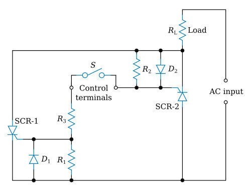
Figure 13: AC Switch With Two SCRs
Control current flows to the gates through resistor R3 when an external switch (mechanical or electronic) connects the control terminals. This switch can be controlled by various sensors like light, heat, or pressure, which activate an electronic amplifier. When the switch closes, the SCRs are triggered with each AC cycle, allowing power to flow to the load. When the switch opens, the SCRs do not fire, and no power is delivered to the load. This mechanism effectively manages the AC power supplied to the load.
Applications and Types of SCRs
SCRs are used in many fields because they have strong control features. These include power conversion, motor control, and lighting systems. Different types of SCRs have been developed to meet specific needs:
Standard SCR: Used for general purposes.
Fast Switching SCR: Designed for high-frequency applications.
Light-Triggered SCR (LTS): Uses light for triggering, providing electrical isolation.
Gate Turn-Off SCR (GTO): Allows both turn-on and turn-off control.
Reverse Blocking SCR: Can block current in both directions.
Three-Phase Bridge SCR Control of Load
Each type of SCR is made for specific needs. Standard SCRs are flexible and used in many applications, while fast-switching SCRs are perfect for high-speed operations. Light-triggered SCRs (LTS) use light to trigger the gate, providing excellent electrical isolation. Gate Turn-Off SCRs (GTO) can both turn on and off, making them suitable for high-power applications. Reverse blocking SCRs are designed to block current flow in both directions, enhancing their use in AC power control scenarios.
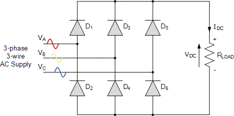
Figure 14: Three-Phase Bridge SCR Control of Load
Practical Applications and Advanced Uses of SCRs
SCRs are widely used in many applications due to their strong control features. Some notable applications include:
Power Conversion Systems: SCRs are key components in power conversion systems, managing the change from AC to DC power and vice versa. These systems are used in both industrial settings and consumer electronics, where a stable and reliable power supply is needed.
Motor Control: In motor control applications, SCRs adjust the speed and torque of electric motors. By changing the firing angle, SCRs control the power delivered to the motor, allowing precise control over its operation.
Lighting Systems: SCRs are used to smoothly dim lights by controlling the phase angle of the AC supply. This ability provides energy savings and enhances the ambiance in lighting applications.
Heating Controls: In heating applications, SCRs regulate the power delivered to heating elements, maintaining the desired temperature with high accuracy. This is especially useful in industrial processes requiring precise temperature control.
Protection Circuits: SCRs act as crowbars in protection circuits, short-circuiting the power supply in case of an overvoltage condition to protect sensitive electronic components from damage.
The wide range of applications shows the flexibility and usefulness of SCRs in modern electronics, where precise control and reliable performance are needed.
Detailed Analysis of SCR Characteristics
Understanding the specific characteristics of SCRs is key for their effective use. Key characteristics include:
Gate Trigger Voltage (VGT)
The minimum gate voltage needed to turn on the SCR.
Holding Current (IH)
The minimum current required to keep the SCR conducting.
Latching Current (IL)
The minimum current needed to keep the SCR in the "on" state after the gate trigger is removed.
Breakover Voltage (VBO)
The voltage at which the SCR will turn on without any gate current.
Forward Blocking Voltage (VDRM)
The maximum voltage that the SCR can block in the forward direction without conducting.
Reverse Blocking Voltage (VRRM)
The maximum voltage that the SCR can block in the reverse direction.
On-State Voltage Drop (VTM)
The voltage drop across the SCR when it is conducting.
dv/dt Rating
The maximum rate of rise of off-state voltage that the SCR can withstand without turning on.
di/dt Rating
The maximum rate of rise of on-state current that the SCR can handle without damage.
SCR Protection and Snubber Circuits
To improve the reliability of SCRs in practical applications, protection circuits are often used. One common method is the use of snubber circuits. Snubber circuits safeguard SCRs from high dv/dt and di/dt stresses, which can cause early failure.
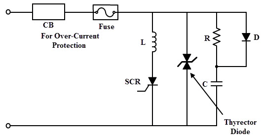
Figure 15: SCR Protection
To protect the SCR from sudden voltage spikes, each SCR in a converter circuit has a parallel R-C snubber network. This snubber network safeguards the SCR against internal voltage spikes that occur during the reverse recovery process. When the SCR is turned off, the reverse recovery current is redirected to the snubber circuit, which contains energy-storing elements.
Lightning and switching surges at the input side can damage the converter or transformer. To reduce the impact of these voltages, voltage clamping devices are used across the SCR. Common voltage clamping devices include metal oxide varistors, selenium thyrector diodes, and avalanche diode suppressors.
These devices have decreasing resistance as the voltage increases, providing a low-resistance path across the SCR when surge voltage occurs. The figure below shows how an SCR is protected from over voltages using a thyrector diode and snubber network.
Advanced Triggering Techniques for SCRs
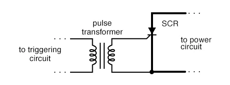
Figure 16: Triggering Technique
Beyond simple gate triggering, advanced methods can further improve SCR performance in complex setups. These methods include:
• Pulse Triggering
Using short, high-current pulses to activate the SCR ensures it turns on reliably even in noisy environments.
• Phase-Controlled Triggering
Aligning the SCR triggering with the AC supply allows precise control over the power sent to the load.
• Optically Isolated Triggering
Using optical isolators to trigger the SCR provides electrical isolation and protects the control circuitry from high voltages.
• Microcontroller-Based Triggering
Using microcontrollers to generate precise triggering pulses allows sophisticated control schemes and better performance in complex setups.
Microcontroller-Based SCR Triggering
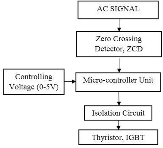
Figure 17: Microcontroller-Based SCR Triggering
These advanced triggering techniques offer more flexibility and control in SCR applications, making them suitable for a wide range of industrial and consumer electronics. By using these methods, engineers can achieve more accurate and reliable control over power management systems, improving the overall efficiency and performance of SCR-based solutions.
SCRs in Modern Power Electronics
SCRs are key parts in creating efficient and reliable power control systems. They make a big difference in several main areas, including:
Renewable Energy Systems: SCRs are used in power inverters and controllers to convert and manage power from renewable sources like solar and wind. They handle high power levels and provide precise control, making them perfect for these applications.
Electric Vehicles: In electric vehicles (EVs), SCRs are used in motor controllers and battery charging systems. They manage the power flow between the battery and the motor, ensuring efficient operation and longer battery life.
Smart Grids: In smart grid applications, SCRs manage the distribution of electrical power. They are used in grid-tied inverters, voltage regulators, and phase angle controllers to ensure stable and efficient power delivery.
Industrial Automation: SCRs are used in motor drives, heating controls, and process control systems in industrial automation. They handle high power and provide precise control, making them core components in automated manufacturing processes.
Uninterruptible Power Supplies (UPS): SCRs provide reliable power backup during outages in UPS systems. They help switch smoothly between the main power supply and the backup power source, ensuring continuous power to key systems.
Future Trends and Innovations in SCR Technology
The development of SCR technology keeps improving to meet the need for better and more reliable power control. New semiconductor materials like silicon carbide (SiC) and gallium nitride (GaN) make SCRs work better by handling higher voltages, reducing resistance, and improving heat management. Integrated Gate Commutated Thyristors (IGCTs) combine the advantages of GTOs and IGBTs, offering fast switching, low energy loss, and the ability to handle high power for demanding applications. Digital control methods with SCRs allow for precise and flexible control, making systems more efficient and reliable. Advances in manufacturing techniques make SCRs smaller and suitable for portable devices, which is helpful for consumer electronics. Enhanced protection features in SCRs, like built-in snubber circuits and overcurrent protection, also make them more reliable and easier to use.
Conclusion
Control current flows to the gates through resistor R3 when an external switch (mechanical or electronic) connects the control terminals. This switch can be controlled by sensors like light, heat, or pressure, which activate an electronic amplifier. When the switch closes, the SCRs trigger with each AC cycle, allowing power to the load. When the switch opens, the SCRs do not fire, stopping power flow. This mechanism controls AC power to the load.
Improvements in semiconductor materials like silicon carbide (SiC) and gallium nitride (GaN) will make SCRs more efficient and durable. Innovations like Integrated Gate Commutated Thyristors (IGCTs) and digital control techniques will enhance SCR performance with faster switching, lower energy losses, and better reliability. SCRs will continue to play a key role in new technologies, from smart grids to electric vehicles, ensuring efficient and reliable power control.
Frequently Asked Questions [FAQ]
1. What are the advantages of silicon controlled rectifier?
The silicon-controlled rectifier (SCR) offers several benefits, including efficient power control, high reliability, the ability to handle high voltages and currents, and precise control over power flow. SCRs also provide fast switching speeds and are durable in harsh environments, making them suitable for various industrial uses.
2. What is the purpose of the silicon rectifier diode?
A silicon rectifier diode is used to convert alternating current (AC) to direct current (DC). It allows current to flow in only one direction, providing rectification, which is needed in power supplies and other electronic circuits.
3. Why do we need controlled rectifier?
Controlled rectifiers are used to precisely manage and control the power flow in electronic devices. They allow for adjusting the output voltage and current, which is needed in applications like motor speed control, power supplies, and dimming lights. Controlled rectifiers improve efficiency and provide stability in power delivery.
5. What is the conclusion of SCR?
The SCR is a versatile and reliable component in power electronics. It provides precise control over high power and voltage applications, making it valuable in various industries. SCRs continue to improve with advancements in materials and technology, ensuring their relevance in future applications.
6. What are the applications of silicon controlled rectifier diode?
Applications of silicon-controlled rectifier diodes include motor speed control, light dimming, power regulation in AC and DC power systems, overvoltage protection, and inverters. They are also used in industrial automation, power supplies, and renewable energy systems like solar and wind power converters.