Understanding the Foster-Seeley Discriminator
The Foster-Seeley discriminator is a kind of FM detector that was widely used in the mid-1900s. It works by using a special transformer to change frequency changes in an FM signal into changes in amplitude. These amplitude changes are then processed to produce a DC output, with the voltage changing based on the frequency of the FM signal. This detector is known for being simple and effective, especially when the signal is strong and steady.This article looks at how the Foster-Seeley discriminator works, explaining its parts, how it operates, and its important role in things like FM radio receivers and radar systems. It also compares it with other FM discriminators, such as the ratio detector and the phase-locked loop (PLL) detector, to understand its benefits, drawbacks, and how well it fits different technologies.
Catalog
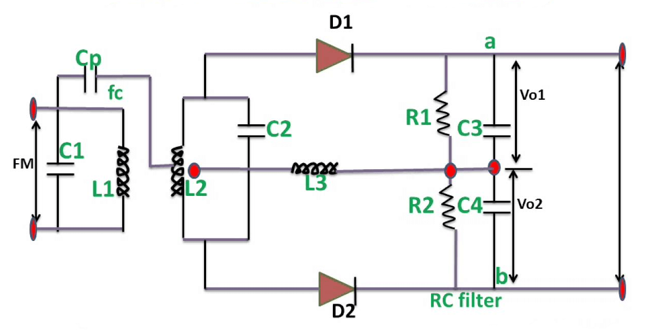
Figure 1: Foster-Seeley Discriminator Circuit Diagram
Origins and Inventors of Foster-Seeley Discriminator
Dudley E. Foster and Stuart William Seeley were important inventors in the field of electronics, best known for creating the Foster Seeley circuit in 1936. This was during a time when radio technology was rapidly growing, and improving radio signals was a main focus. Foster worked as an engineer at Western Electric, while Seeley was with RCA. Together, they made a circuit that helped improve frequency modulation (FM) technology, solving problems related to radio frequency stability.
The Foster Seeley circuit was originally designed to keep radio frequencies stable during transmission, which is called automatic frequency control. It was later discovered that it was also great at FM demodulation, means it could turn frequency changes into sound. The circuit's steady and reliable performance made it part of FM radios.
From the 1930s to the 1970s, the Foster Seeley circuit was commonly used in radios for decoding FM signals. It played an important role in World War II and in both military and civilian communication systems. Its simple design made it popular for many years. By the late 20th century, integrated circuits (ICs) became widely used. These small chips could hold thousands of transistors, making devices smaller, cheaper, and more efficient. As a result, newer methods for FM decoding replaced the Foster Seeley circuit, and it became outdated, reflecting a major shift toward compact and digital technology in the electronics industry.
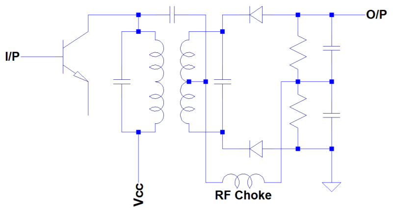
Figure 2: Foster-Seeley Discriminator
Components of the Foster-Seeley Discriminator
Transformer
The main part of the Foster-Seeley discriminator is a transformer with a center-tapped secondary coil. This transformer splits the FM signal into two opposite currents. The center tap is grounded, and the two halves of the signal go to separate diodes. This setup helps compare the differences in phase and amplitude that are required for accurate signal decoding.
One main difference is that the Foster-Seeley discriminator does not have a third winding on the transformer. The ratio detector uses an extra winding to help make the decoding more stable, especially when the signal strength changes. This extra winding also makes the ratio detector less sensitive to amplitude variations.
Choke
The choke in this circuit keeps the output stable by maintaining a constant DC level. It is placed where the rectified signals from the diodes meet. The choke helps smooth out high-frequency noise and controls the flow of current. Without it, the output would be unstable, affecting the decoded signal.
In the Foster Seeley circuit, the choke plays a role similar to the third winding in the ratio detector but is less effective. While the choke helps stabilize the output, it doesn’t fully handle changes in amplitude as well as the third winding in the ratio detector. This makes the Foster-Seeley discriminator simpler and cheaper to build but more likely to be affected by changes in signal strength.
Diodes
Two diodes are placed symmetrically on either side of the transformer’s secondary coil. Each diode processes the signal from its side, creating two separate DC voltages. These voltages are then compared to measure changes in the FM signal. The balanced setup of the diodes ensures the output closely matches the original signal, even if the input amplitude changes.
Capacitors
Capacitors are important in circuits that match the FM signal's frequency. They work with diodes and the transformer to filter out unwanted signals, allowing only the right ones to pass. Along with the transformer, they help divide the signal into the right parts and keep it balanced. Capacitors help keeping the circuit's frequency stable and the signal steady.
Load Resistors
Load resistors are found at the output of the diodes, where they turn the current into a matching voltage. This voltage holds the final signal that contains the original sound or data. The resistors help form the correct signal, allowing the original content to be recovered after the demodulation process.
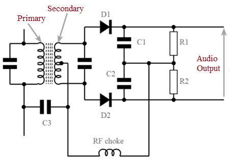
Figure 3: Foster-Seeley Discriminator Components
How Does the Foster-Seeley Discriminator Work?
The Foster-Seeley discriminator works by turning the changes in frequency of an FM (Frequency Modulation) signal into something useful, like sound. Unlike AM (Amplitude Modulation), which changes how strong a signal is, FM changes its frequency. The discriminator's job is to pick up and understand these changes so that other parts, like speakers, can use the information.
The core of the discriminator has two circuits made of coils and capacitors. These circuits are carefully adjusted to match the main frequency of the FM signal. As the signal goes through these circuits, they react to its frequency changes, and helps turn those changes into electrical signals that can be processed further.
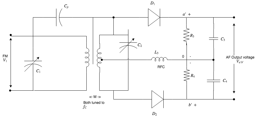
Figure 4: Foster-Seeley Discriminator Work
A main part of the discriminator is the transformer, it has a special center-tapped winding. This transformer splits the FM signal into two parts that are the same but with opposite phases—when one signal rises, the other falls, like mirror images.
This splitting gets the signals ready for the next step, where the frequency changes will be turned into variations in signal strength. These two signals are sent to separate diodes, and turn the alternating current (AC) into direct current (DC). This gives two DC outputs, one for each part of the split signal.
Circuit Behavior with Matched and Mismatched Frequencies
Matched Frequency (No Deviation): When the incoming signal frequency exactly aligns with the center frequency of the tuned circuits, the signal splits evenly as it passes through the two halves of the transformer. Both portions of the signal remain perfectly balanced. After passing through the diodes, the rectified signals produce equal but opposite voltages. These opposing voltages cancel each other out, resulting in no output voltage. This balanced state occurs when there is no modulation, representing the carrier frequency.
Mismatched Frequency (Deviation): When the incoming signal frequency shifts away from the center frequency, due to modulation, the balance between the two signals is disturbed. If the frequency rises above the center frequency, one side of the circuit generates a higher voltage than the other. Conversely, if the frequency drops below the center frequency, the other side produces the higher voltage. The diodes rectify these unequal signals, and the difference in voltages creates either a positive or negative output voltage. Whether the output is positive or negative depends on whether the frequency shift is above or below the center. This output voltage is directly related to the amount of frequency deviation and carries the modulated information.
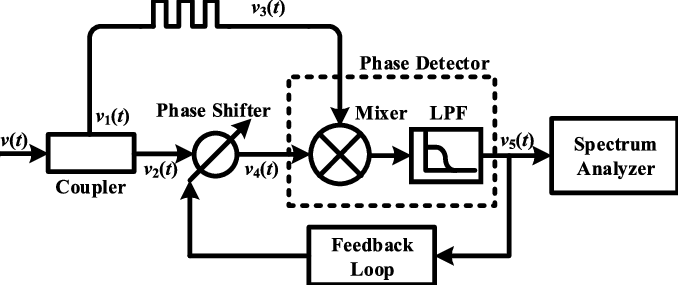
Figure 5: Schematic of the Delay-line-based Frequency Discriminator System
Phase Difference in Signal Processing and Effects of Modulation and Demodulation
The difference in phase between signals plays an important role in signal processing, especially in how the Foster-Seeley discriminator works. When an FM signal goes into the discriminator, it gets divided into two paths by a transformer. This transformer creates two signals that are exactly opposite in phase (180 degrees apart). This phase difference is need for the circuit’s diodes to correctly detect changes in the signal’s frequency.
As the frequency of the incoming signal changes due to modulation, the phase difference between the two paths changes slightly. This shift in phase is connected to the frequency variation. When the frequency moves away from the central value, the phase difference becomes more noticeable. These phase changes affect the strength of the signals reaching the diodes, causing different voltage levels.
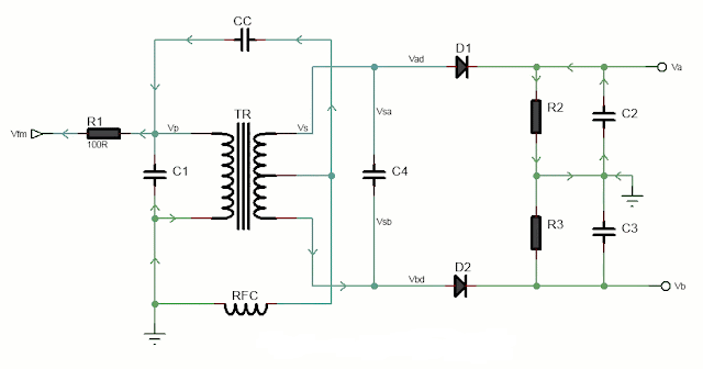
Figure 6: Foster-Seeley Discriminator Demodulation
Impact of Modulation: Modulation changes the frequency of the FM signal based on the amplitude of the original signal. These frequency changes affect the phase difference between the two signals in the discriminator. The circuit detects these shifts and turns them into voltage changes that represent the original modulating signal.
Impact of Demodulation: During demodulation, the discriminator uses the phase differences to produce a voltage that matches the frequency changes in the FM signal. This voltage corresponds to the original signal, like an audio stream, that can then be processed or amplified for listening.
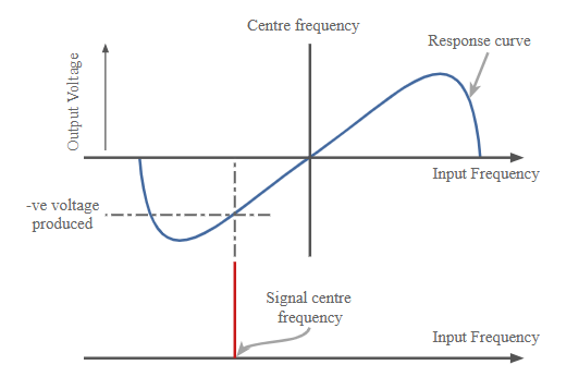
Figure 7: Demodulator Curve
Applications of the Foster-Seeley Discriminator
FM Radio Receivers
The Foster-Seeley discriminator is best known for its use in FM radios. Before this method was developed, earlier ways of decoding FM signals weren’t as good and caused more distortion. Thanks to the Foster-Seeley discriminator, FM radios now produce clearer sound, making music and broadcasts much better for millions of listeners today.
Telecommunications
In telecommunications, clear signal decoding is required for smooth communication. The Foster-Seeley discriminator is used in systems like microwave and satellite communications, often use frequency modulation to send data over long distances. It helps extract data accurately from the signal, making sure that voice, video, or other information is transmitted clearly.
Radar Systems
Radar systems use frequency modulation to track distances and detect moving objects. The Foster-Seeley discriminator helps process the radar signals, allowing the system to calculate the location and speed of objects correctly. Without it, radar accuracy would drop, affecting important systems like air traffic control and weather monitoring.
Two-Way Radios
In devices like walkie-talkies and short-range communication radios, the Foster-Seeley discriminator helps provide clear voice transmission. This is important for emergency services, the military, and other industries where clear communication is required, especially in noisy or difficult environments.
Aircraft and Marine Communications
In aviation and marine systems, FM signals are used because they resist noise and interference. For example, aircraft radios use FM to talk with air traffic control. The Foster-Seeley discriminator makes sure these signals are decoded correctly, ensuring smooth and clear communication like emergency situations.
Automatic Frequency Control (AFC) Systems
The Foster-Seeley discriminator useful in systems that need to keep frequencies steady, like TV receivers and communication equipment. It helps the system correct any frequency changes in real time, making sure the signal stays strong and stable for better performance.
Comparative Analysis of FM Discriminators
Foster-Seeley Discriminator vs. Ratio Detector
Both the Foster-Seeley discriminator and the ratio detector are designed to demodulate frequency-modulated (FM) signals, yet they operate with distinct configurations and performance traits. The Foster-Seeley discriminator uses a double-tuned RF transformer and a pair of diodes. This setup converts frequency shifts into changes in amplitude, and then translated into voltage that represents the original signal.
The ratio detector operates similarly but includes enhancement: an extra capacitor that improves its ability to reject amplitude variations. This feature makes the ratio detector more stable and less vulnerable to noise than the Foster-Seeley discriminator. However, it requires more precision during alignment and calibration. While both offer good linearity and sensitivity, the ratio detector performs better when the signal is exposed to amplitude changes.
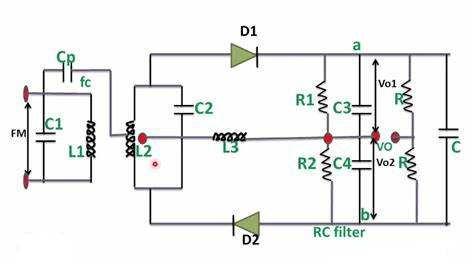
Figure 8: Circuit Diagram of Ratio Detector
Foster-Seeley Discriminator vs. Quadrature Detector
The quadrature detector takes a different approach from the Foster-Seeley discriminator when demodulating FM signals. While the Foster-Seeley discriminator converts frequency deviations into amplitude changes, the quadrature detector shifts the phase of a reference signal by 90 degrees relative to the incoming FM signal. By mixing the phase-shifted and received signals, the output directly correlates to the frequency deviation.
The quadrature detector excels in handling signal amplitude fluctuations, making it highly effective in noisy conditions. In comparison, the Foster-Seeley discriminator is more susceptible to noise and requires careful adjustment of its components to work effectively. Because of this, the quadrature detector is often preferred in digital communication systems.
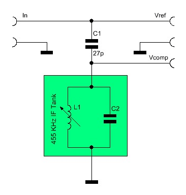
Figure 9: Quadrature Detector Works
Foster-Seeley Discriminator vs. Phase-Locked Loop (PLL) Detector
When comparing the Foster-Seeley discriminator with a phase-locked loop (PLL) detector, the differences in technology and performance become clear. A PLL locks onto the phase of the incoming FM signal and continuously adjusts a local oscillator to maintain a consistent phase relationship. This process demodulates the signal with high precision. PLL detectors outperform the Foster-Seeley discriminator in terms of frequency stability, noise resistance, and the ability to handle larger frequency deviations.
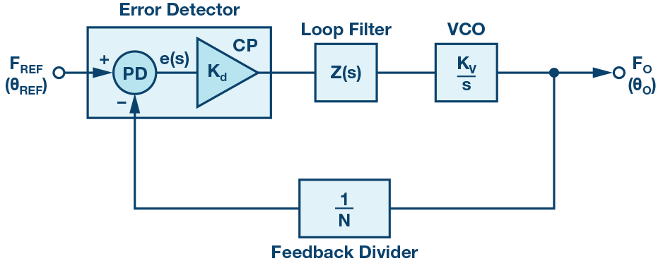
Figure 10: Phase-Locked Loop (PLL) Detector Diagram
Foster-Seeley Discriminator vs. Zero Crossing Detector
The zero crossing detector offers a much simpler approach to FM demodulation by identifying when the signal crosses the zero voltage line. This method contrasts sharply with the Foster-Seeley discriminator, that relies on a more intricate design to translate frequency changes into amplitude variations.
While the zero crossing detector is easy to implement and cost-effective, it tends to be less accurate and more susceptible to noise. It works well in low-cost applications where high signal fidelity is not a priority. On the other hand, the Foster-Seeley discriminator, though more complex, offers much better signal quality and is ideal for applications requiring higher accuracy in demodulation.
Figure 11: Zero Crossing Detector Diagram
Foster-Seeley Discriminator vs. Slope Detector
The slope detector is another simpler alternative for FM demodulation. It uses a single-tuned circuit, with its frequency response curve positioned slightly off-center from the carrier frequency. As the FM signal passes through, the frequency deviations produce voltage changes based on where they fall along the slope of the response curve.
Though easy and inexpensive to construct, the slope detector is less precise and more prone to noise and signal variations. In contrast, the Foster-Seeley discriminator's balanced configuration provides greater stability and accuracy, making it the better option when reliable and high-quality FM demodulation is required.
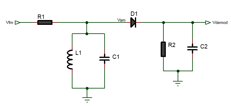
Figure 12: Slope Detector Diagram
Advantages and Disadvantages of the Foster-Seeley Discriminator
|
Advantages |
Disadvantages |
|
Simple Design: Mainly uses a transformer
and a diode ring, making it easy to build and maintain. |
Sensitive to Amplitude Noise: Doesn't
filter out changes in signal strength, allowing noise to affect FM decoding. |
|
Easy to Tune: No specialized skills required
for tuning, making it user-friendly. |
Higher Cost: While basic parts are
affordable, additional circuits like limiters can increase costs. |
|
High Output Voltage: Produces high output
voltage during frequency changes, reducing the need for extra amplification. |
Wide Bandwidth Required: Needs a larger
bandwidth to operate effectively, which can be limiting in some applications. |
|
Accurate and Reliable: Provides clear and
high-quality audio, maintaining signal clarity. |
Size Limitations: Transformer and related
parts make it bulky, challenging for compact devices. |
|
Consistent Linearity: Offers steady
performance across a wide range of signal levels, ensuring stability even in
fluctuating conditions. |
Conclusion
The Foster-Seeley discriminator, with its detailed design and effective operation, is a main tool for demodulating FM signals. Although it has some weaknesses, like being sensitive to noise and needing a wide bandwidth, it has benefits such as a simple design, easy tuning, and producing high output voltage. This makes it a popular choice in many uses. It helps deliver clearer sound in FM radios and improves the reliability of telecom and radar systems. Even though newer technologies offer better noise resistance and stability, the Foster-Seeley discriminator is still important in electronics, especially when low cost and reliability are required. Its continued use shows the value of knowing both its strengths and weaknesses as frequency modulation technology advances.
Frequently Asked Questions [FAQ]
1. What is the Foster-Seeley discriminator?
The Foster-Seeley discriminator is an electronic circuit used to demodulate frequency-modulated (FM) signals. The circuit includes a transformer with a center-tapped secondary winding and two diodes, which are configured in a way that they can detect the difference in phase between an input signal and a locally generated reference signal. This phase difference, varies with the frequency of the incoming FM signal, is converted into a corresponding amplitude variation, effectively demodulating the frequency variations back into the original audio or data signal.
2. What is the function of discriminator in FM receiver?
In an FM receiver, the discriminator's function is to convert frequency variations in the received signal into amplitude variations in voltage, that are easier to process and convert back into the original audio or data format. This process is important as the information in an FM signal is encoded in the frequency deviations from a carrier frequency, rather than amplitude variations. The discriminator enables the receiver to detect these deviations and translate them into a usable form.
3. What is the difference between ratio detector and Foster-Seeley discriminator circuit?
Both the ratio detector and the Foster-Seeley discriminator are used for demodulating FM signals, but they differ in design and performance. The ratio detector uses a similar setup with a transformer and diodes but includes an additional capacitor that provides automatic amplitude regulation and improved noise rejection. This makes the ratio detector more stable and less prone to noise compared to the Foster-Seeley discriminator. The Foster Seeley, on the other hand, is simpler and was more popular in earlier radio technology due to its straightforward implementation but is more sensitive to amplitude variations and noise.
4. What is a discriminator in a receiver?
A discriminator within a receiver is a circuit that performs the function of demodulation for frequency-modulated signals. It serves as component that extracts the audio or data information from the carrier wave by detecting frequency shifts and converting them into voltage variations that represent the original signal.
5. What is the use of frequency discriminator?
A frequency discriminator is used to demodulate frequency-modulated signals by converting changes in the frequency of the received signal into corresponding changes in voltage. This is good in communication systems where data or audio information is transmitted over distances using FM, as it allows the receiver to accurately reconstruct the transmitted information from the frequency variations of the received signal.