Understanding Operational Amplifiers
Operational Amplifiers (Op-amps) are needed in analog electronics, known for their precision and efficiency in amplifying voltage signals. This article digs into the diverse nature of Op-amps, exploring their operational principles, classifications, and applications in various electronic circuits. Op-amps are versatile, performing serious analog signal processing tasks such as filtering, signal conditioning, and executing basic mathematical operations, dynamic for advanced signal processing and control systems. It also examines the structural and functional nuances of different Op-amp types, including voltage, current, and summing amplifiers, and their role in enhancing the performance and reliability of electronic devices. By exploring their characteristics, such as high input impedance and low output impedance, this object highlights the key role Op-amps play in modern electronic design, ensuring minimal signal loss and optimal performance across diverse applications.Catalog
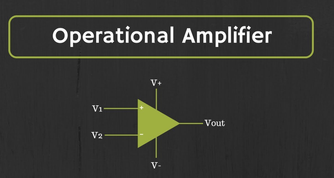
Figure 1: Operational Amplifier
Understanding Operational Amplifiers
An Operational Amplifier, or Op-amp, is a key component in analog electronics, serving as a high-gain voltage amplifier that efficiently amplifies small voltage differences between its two input terminals—the inverting and non-inverting inputs. Op-amps are extremely versatile, pairing effectively with passive components like resistors and capacitors to facilitate a range of analog signal processing tasks. Primarily excelling in direct current (DC) linear amplification, Op-amps are instrumental in signal conditioning, filtering, and executing basic mathematical operations such as addition, subtraction, integration, and differentiation, which are useful for complex signal processing and control systems. In addition, the cost-effectiveness and robustness of Op-amps, underscored by their resilience to short circuits, make them a staple in analog circuit design, generally costing less than a dollar per unit.
The performance of an Op-amp heavily relies on the application of feedback, particularly negative feedback, which is significant for stabilizing the gain, enhancing accuracy, and increasing the bandwidth of the amplifier. By feeding a portion of the output back to the inverting input, negative feedback not only reduces the overall gain but also improves linearity and bandwidth, principles that are eventually in control theory and prevalent across various engineering disciplines. Op-amps are distinguished by their high input impedance and low output impedance, making them ideal for interfacing with different circuit stages without significant signal loss. The output of an Op-amp represents the amplified difference between the input voltages, scaled by the amplifier's gain, which can be finely adjusted with external resistors in the feedback loop to precisely control the amplifier's performance within a circuit.
Classifying Operational Amplifiers
Operational Amplifiers (Op-amps) are classified into four main types based on the relationship between their input and output signals:
• Voltage-to-Voltage
• Current-to-Current
• Voltage-to-Current (Transconductance)
• Current-to-Voltage (Trans resistance)
This classification is needed because it aligns each Op-amp type with specific functions and application areas. The focus here will primarily be on voltage amplifiers, where both input and output signals are in voltage form, reflecting their common use in signal amplification tasks.
Voltage Amplifier Op-amps
The center operation of a voltage amplifier Op-amp is based on its function as a differential amplifier. In this configuration, the Op-amp outputs a voltage that is the amplified difference between the voltages at its two inputs. The key benefit of this differential operation is its high Common Mode Rejection Ratio (CMRR). CMRR measures the Op-amp's ability to suppress common-mode signals—voltages that are present simultaneously at both inputs—thereby improving the accuracy and stability of the voltage amplification.
In practical use, this capability allows Op-amps to perform well in noisy environments, where distinguishing between the actual signal and noise is settling. A higher CMRR means the Op-amp can better reject noise, making it ideal for applications requiring precise electronic signal processing. This selective amplification is dynamic in fields ranging from audio equipment to instrumentation and control systems, where accuracy and signal integrity are serious.
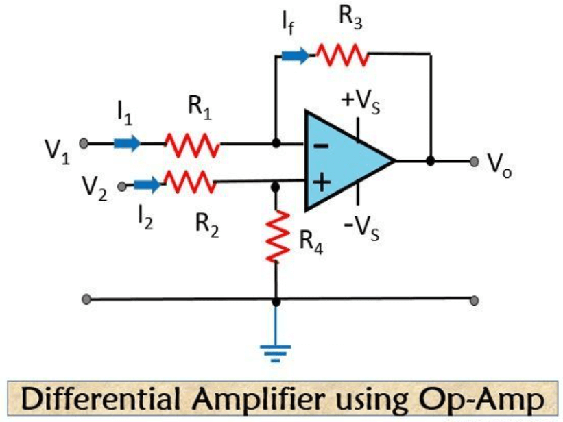
Figure 2: Differential Amplifier
Differential Amplifiers: Core Principles and Applications
At the center of an operational amplifier (Op-amp) is the differential amplifier, required for its functionality, consisting of two transistors—commonly bipolar junction transistors (BJTs) or field-effect transistors (FETs)—that are identically biased to operate at a common point. This precise matching is a must for symmetrical behavior, which is key to the amplifier's stability and efficiency. In a standard differential amplifier configuration, the emitters (or sources in the case of FETs) of these transistors are interconnected and often connected to the power supply through a common emitter (or source) resistor. This setup helps stabilize the operating point against variations in the input signal or power supply fluctuations, ensuring the amplifier maintains consistent performance even under dynamic conditions.
|
|
Differential Amplifiers |
|
Functionality and Performance
|
The differential amplifier's primary function is to amplify the voltage difference between its two input terminals, which are ideally 180 degrees out of phase. This phase opposition means that any common-mode voltage—voltage common to both inputs—produces no change in the output. The ability to suppress common-mode signals is measured by the Common Mode Rejection Ratio (CMRR), a risky performance metric in practical applications |
|
Output Characteristics |
The differential amplifier can produce balanced outputs at the collectors (or drains) of the transistors. These outputs can swing in opposite directions to amplify differential signals or move together when common-mode signals are present. Ideally, common-mode signals result in no output, emphasizing the amplifier's ability to reject noise and interference.
|
|
Biasing and Interdependence
|
Adjusting the biasing of one transistor inversely affects the other due to their interconnected nature, maintaining a constant current flow across the common emitter/source resistor. This interdependence minimizes any imbalance in the transistors’ characteristics, which settles for achieving high linearity and low distortion in the output signal.
|
Figure 3: Summing Amplifier
Characteristics of Summing Amplifier
The Summing Amplifier showcases the operational versatility of Op-amps by enabling the linear combination of multiple input signals. This configuration uses multiple input resistors connected to a single inverting input of the Op-amp. The output voltage is a weighted sum of the input voltages, scaled according to the values of the respective input resistors.
In a summing amplifier, each input voltage is scaled inversely proportional to its associated input resistor and the common feedback resistor. By adjusting these resistor values, you can precisely control the impact of each input on the final output. The nature of the summing amplifier's operation inverts the total sum of these inputs, producing an output that is the negative sum of the scaled inputs.
This ability to sum and scale inputs makes the summing amplifier ideal for combining multiple signal sources. It is particularly useful in applications such as audio mixing, data acquisition systems, and computational analog circuits. Engineers can design complex signal processing functions with this topology, maintaining control over the amplitude and phase relationships between the combined signals.
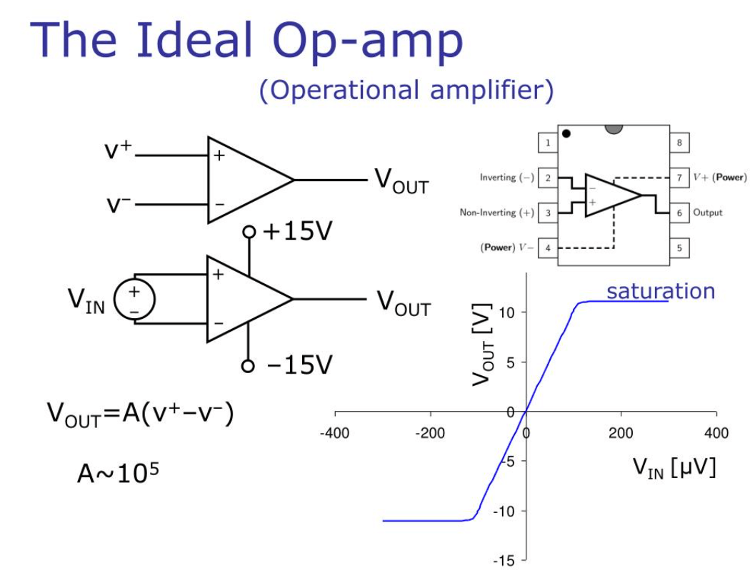
Figure 4: Ideal Operational Amplifier
Op-amp Parameters and Idealized Characteristics
An ideal operational amplifier (Op-amp) is characterized by several optimal parameters that serve as benchmarks for evaluating real-world devices.
Infinite Open-Loop Gain (Avo): This allows for significant signal amplification without inherent limitations, ensuring the amplifier can amplify even the smallest signals.
Infinite Input Impedance (Zin): This prevents the Op-amp from loading the signal source, allowing for accurate signal transfer without affecting the source.
Zero Output Impedance (Zout): This ensures perfect power transfer to any load without loss, maximizing the efficiency of the signal output.
Infinite Bandwidth (BW): This characteristic means the Op-amp can amplify signals of any frequency without attenuation, making it suitable for a wide range of applications, from DC to high-frequency AC signals.
Zero Offset Voltage (Vio): This ensures that the output voltage is zero when the input is zero, eliminating the need for adjustments and ensuring accurate signal representation.
Overview of Configuration Topologies in Operational Amplifiers
Operational amplifier (Op-amp) circuits can be designed in various topologies, each tailored for specific applications. The main configurations include the Voltage Follower, Inverting Amplifier, Non-inverting Amplifier, and Voltage Comparator. Each serves a unique purpose in circuit design.
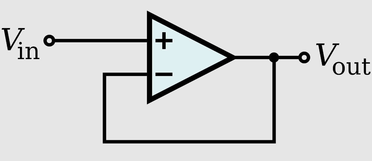
Figure 5: Voltage Follower
• Voltage Follower
Configuration features high input impedance and low output impedance. It replicates the input voltage at the output without amplifying it. This setup acts as an excellent buffer, isolating the source from the load while maintaining signal integrity. It's significant in applications where you need to isolate the signal without changing its magnitude.
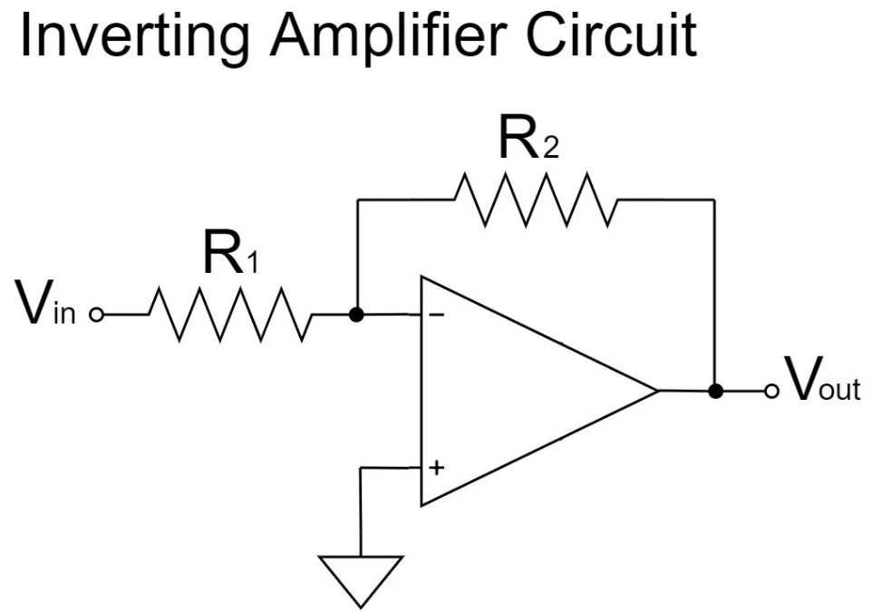
Figure 6: Inverting Amplifier
• Inverting Amplifier
Configuration produces an output that is an amplified, phase-inverted version of the input. This setup uses a feedback resistor network to set the gain. The gain is determined by the ratio of the feedback resistor to the input resistor. This topology is needed for applications requiring signal inversion and precise gain settings.
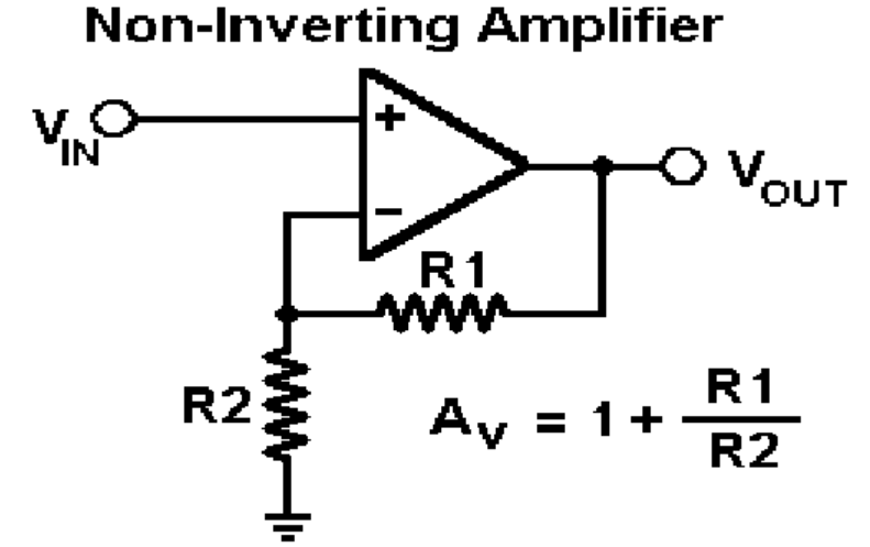
Figure 7: Non-inverting Amplifier
• Non-inverting Amplifier
Maintains phase coherence between the input and output signals. It also uses a feedback resistor network to control the gain. The gain in this configuration is set by the relationship between the feedback resistors, resulting in a non-inverted, amplified version of the input signal. This is useful in applications where maintaining the phase of the signal is serious.
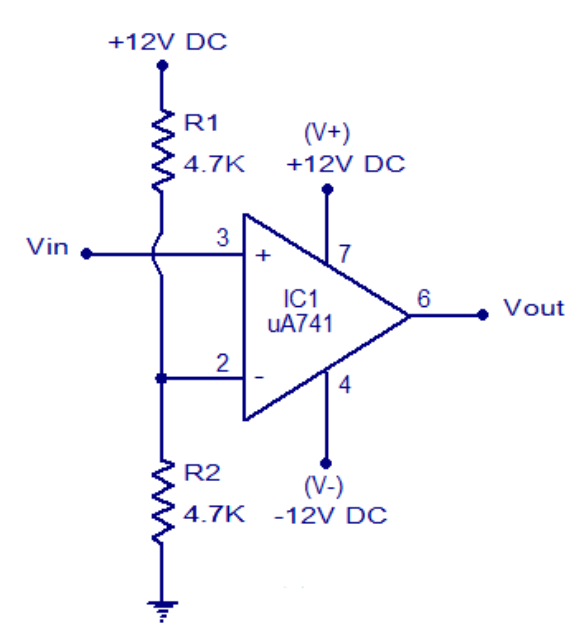
Figure 8: Voltage Comparator
• Voltage Comparator
Operates in an open-loop configuration, comparing two input voltages and driving the output to the supply voltage limits based on which input is higher. This rapid response makes it ideal for decision-making circuits, such as threshold detectors and switching controllers, where quick, binary outputs are required based on input comparisons.
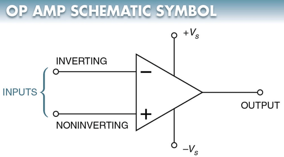
Figure 9: Symbol of an Operational Amplifier
The Symbolic Representation of Operational Amplifiers
The standard symbol for an operational amplifier (Op-amp) is a triangle, which schematically represents its basic connections and function. This triangular symbol typically has three terminals: two for inputs and one for output. The inverting input is marked with a minus (-) sign, and the non-inverting input is marked with a plus (+) sign. The single output is located at the apex of the triangle, opposite the base where the inputs are positioned.
While the basic symbol captures the essence of an Op-amp’s functionality, some variations include additional pins for power supply connections (positive and negative supply voltages). These are often omitted in basic circuit diagrams to keep them clear and simple. However, including power supply terminals in detailed schematics is key for understanding the complete operational context of the Op-amp.
The orientation and labeling of the input terminals are unsafe because they influence the phase connection of the output relative to the inputs. The symbol conveys this relationship, helping engineers and technicians quickly understand and integrate the component into larger circuit designs.
Key Features and Attributes of Operational Amplifiers
Ground Independence
One key feature of operational amplifiers (Op-amps) is their ability to operate without a direct ground connection. Instead, all terminal voltages are defined relative to a common mode point, typically set at the midpoint between the positive and negative power supplies. This allows Op-amps to function effectively without relying on a ground reference, making them adaptable to various electronic circuits.
Advantages in Dual Power Supply Applications
This characteristic is especially beneficial in applications using dual power supplies, as it enables the Op-amp to handle both positive and negative input voltages effectively. It also facilitates the integration of Op-amps into complex multi-stage amplifiers and mixed-signal circuits without requiring a common ground path. This reduces potential ground loop issues and simplifies the overall circuit design. The ability to operate independently of a ground reference enhances the versatility and adaptability of Op-amps. They become requisite in diverse applications, from basic signal buffering to sophisticated feedback networks.
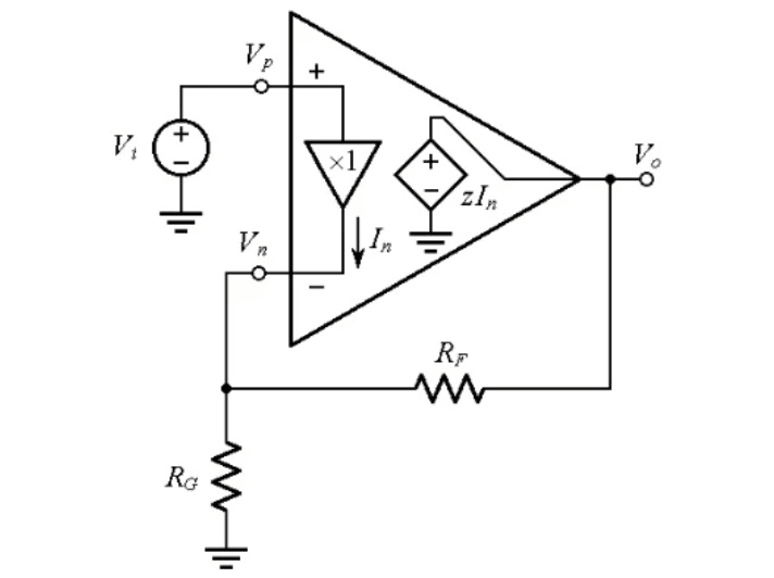
Figure 10: Voltage vs Current Feedback Operational Amplifiers
Comparing Voltage and Current Feedback in Operational Amplifiers
Operational amplifiers (op-amps) are required components in electronic circuit design. Among them, voltage feedback op-amps are the most common, known for their predictable performance in various applications. These op-amps maintain a constant gain-bandwidth product, which simplifies design because their behavior can be easily anticipated. In difference, current feedback op-amps are less common but offer unique advantages, especially in high-speed applications. Unlike voltage feedback op-amps, they have a variable gain bandwidth product. This variability allows for better performance at high frequencies, making them ideal for applications that require fast response times and wide bandwidth.
Using current feedback op-amps effectively requires a detailed understanding of their operational dynamics. Engineers must consider the fluctuating gain bandwidth relationship, which means circuit integration and optimization must be approached with greater care. This involves a thorough examination of the op-amp's response under different load conditions and an exploration of stability criteria to ensure reliable high-speed operation.
Therefore, deploying current feedback op-amps in a circuit not only requires knowledge of their basic electrical properties but also a strategic approach to maximize their high-speed capabilities without sacrificing stability and efficiency.
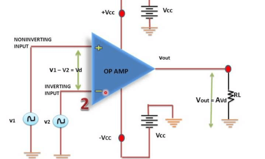
Figure 11: Closed-Loop Operation of an Operational Amplifier
Mastering Closed-Loop Operations with Operational Amplifiers
In operational amplifier (op-amp) applications, the closed-loop configuration is widely used due to its stability and reliability. Open-loop setups, while sometimes useful, often face instability because of high gains. In an open-loop configuration, the op-amp operates without feedback, making it prone to amplifying noise and other unwanted signals. This high gain causes even small inputs to drive the output to the power supply limits, making it impractical for precise amplification. As a result, open-loop op-amps are typically used as comparators rather than amplifiers.
On the other hand, closed-loop operation introduces negative feedback, where the output is fed back to one of the input terminals. This feedback mechanism stabilizes the op-amp by reducing the overall gain. Negative feedback ensures that the inverting and non-inverting inputs balance at the same voltage, significantly enhancing the amplifier's stability and reliability.
There are two main types of closed-loop configurations: inverting and non-inverting. In the inverting setup, the output is fed back into the inverting input. This configuration is favored for its simplicity and effectiveness in managing feedback. It allows precise control over the amplifier's gain, which is key for accurate signal amplification. Engineers prefer the inverting model for its straightforward implementation and consistent performance across various conditions, from basic signal buffering to complex signal processing tasks.
Strategies for Selecting the Ideal Operational Amplifier
Selecting the right operational amplifier (op-amp) for a specific application requires understanding several risky parameters. First, consider the operational voltage range. The op-amp's voltage range must match the available voltage levels in your environment. Check the op-amp's datasheet to ensure it supports the supply voltages, whether it's a single positive supply or dual supply (positive and negative). Dual supplies are imperative for applications that process negative voltages.
Next, evaluate the Gain Bandwidth Product (GBP). For high-frequency applications or those needing low distortion, choose an op-amp with a high GBP. While op-amps with higher GBP handle higher frequencies better, they also consume more power. Power efficiency is significant, especially in battery-operated or energy-sensitive applications. Calculate the power requirements by multiplying the supply current by the voltage and compare this with the datasheet specifications to determine the op-amp's efficiency and suitability.
The selection process goes beyond matching specifications. It involves understanding how these factors interact under real conditions. For instance, an op-amp with a higher GBP may be advantageous, but it increases power demands and potential thermal issues in compact or poorly ventilated environments.
Advantages and Limitations of Operational Amplifiers
Operational amplifiers (op-amps) play a key role in modern electronic design, providing compact, efficient, and versatile solutions for various analog functions like filtering, voltage buffering, and signal comparison. These devices, usually available as integrated circuits (ICs), are easy to integrate into different systems. Designers can choose from various performance levels to match their specific application needs. In addition, many manufacturers offer simulation tools like PSPICE models, enabling engineers to model and resolve potential issues before moving to hardware implementation. However, using op-amps effectively comes with its challenges. Since op-amps are analog components, a deep understanding of analog principles is needed. This includes knowledge of loading effects, frequency response, and circuit stability. A common issue is unexpected oscillations, often arising from overlooking risky design parameters during the planning stage.
Conclusion
Operational Amplifiers (Op-amps) represent a cornerstone of modern electronic design, offering unparalleled versatility and efficiency in amplifying and processing analog signals. This article has traversed the complex landscape of Op-amp functionality, from their basic operational principles to advanced configurations and applications in various electronic systems. The detailed examination of Op-amp classifications, including differential, voltage follower, and summing amplifiers, reveals their adaptability and serious role in achieving precise electronic signal processing, particularly in environments where noise and signal integrity are dominant. The discussion highlighted the operational challenges and limitations inherent in integrating these components into sophisticated electronic circuits, emphasizing the necessity of a deep understanding of analog principles to mitigate issues such as oscillations and instability. As electronic design continues to evolve, the insights gleaned from this comprehensive exploration of Op-amps will undoubtedly aid engineers and designers in leveraging these components to their fullest potential, thereby enhancing the functionality and efficiency of electronic systems in an increasingly digital world.
Frequently Asked Questions [FAQ]
1. What are the possible applications of operational amplifiers (op-amps)?
Operational amplifiers are versatile components used in electronic circuits. Their applications include signal conditioning, filtering, and amplification. They are integral in building active filters, voltage comparators, and oscillators. In practical use, op-amps are needed for analog signal processing, forming the backbone of audio amplifiers, and are used to construct precision instrumentation that requires high sensitivity and stability.
2. Why are operational amplifiers chief?
Op-amps are key due to their flexibility and functionality. They can perform mathematical operations such as addition, subtraction, integration, and differentiation on analog signals, which are dynamic for signal processing. Their high input impedance and low output impedance make them ideal for use in a wide range of applications without affecting the rest of the circuitry.
3. How do operational amplifiers (OP amps) work?
An op-amp amplifies the difference in voltage between its two input pins, the inverting (-) and non-inverting (+) inputs. It outputs a voltage typically hundreds of thousands of times the voltage difference between its input pins. Inside, the op-amp uses a series of transistors, resistors, and capacitors to achieve this high gain. Feedback mechanisms, usually involving external resistors or capacitors, are employed to control the overall gain and behavior of the op-amp in a circuit.
4. What is the basic function of op amp?
The ultimate function of an op-amp is to amplify an electrical signal, delivering a much larger output in voltage relative to the input difference between its two inputs. This capability allows it to serve as a key building block in analog electronic circuits, facilitating a wide range of operations from basic amplification to complex feedback and control systems.
5. Why are operational amplifiers significant?
The importance of op-amps stems from their integral role in analog electronics. They enable precise control of analog signals, which is required in various applications across medical instrumentation, audio processing, and telecommunications. Their ability to function in different configurations also allows for extensive flexibility in designing electronic circuits, making them requisite in modern electronics.