Understanding and Building Op-Amp Based Peak Detectors
In the world of electronic circuit design, peak detectors are key tools for accurately analyzing and processing signal strengths. These circuits are designed to find and keep the highest signal amplitude, making sure the peak value is precisely captured and held as needed. Peak detectors are important in many fields, from improving audio quality in communication systems to aiding medical diagnoses with devices like electrocardiograms. This article looks into peak detectors, covering their main types, how they work, and the technology behind them. It discusses both passive and active peak detectors, explaining the roles of components like diodes, capacitors, and operational amplifiers. It also explains the different phases of operation, including charging and holding phases, and explores how peak detectors are used in modern electronic systems with examples of integrated circuits (ICs).Catalog
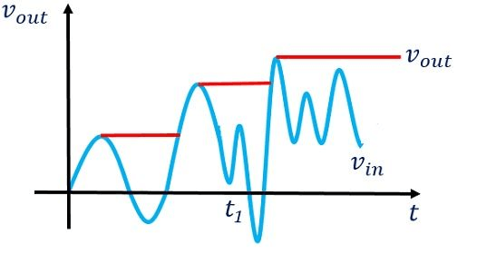
Figure 1: Peak Detector
What is a Peak Detector?
A peak detector is an electronic circuit that finds and holds the highest amplitude of a signal for a specified time. This function is beneficial in many areas where capturing the peak value of a waveform is needed for accurate signal analysis and processing. The peak detector continuously monitors the incoming signal and updates its output to match the highest value observed, holding this value until a new peak is detected.
Peak detectors are key to preventing signal distortion by keeping audio levels within equipment capabilities. Communication systems use them to maintain signal integrity, especially in environments where signal strength varies greatly. In medical devices like electrocardiograms (ECGs), peak detectors accurately capture maximum pulses for diagnostic purposes.
Basic peak detectors use a diode, capacitor, and resistor to direct and store peak voltage, with the resistor discharging the capacitor slowly. Advanced designs with operational amplifiers improve response time and stability, good for precise and reliable performance in modern electronics.
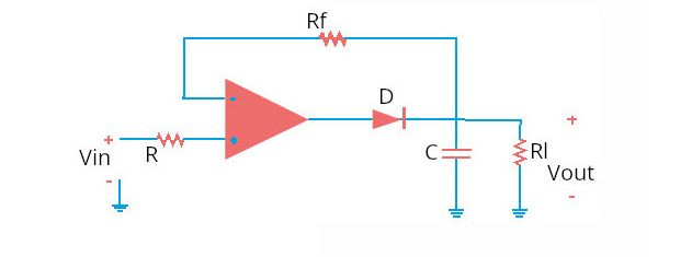
Figure 2: Peak Detector Circuit
Active Peak Detector
Active peak detectors use components like operational amplifiers (op-amps) and transistors to improve their accuracy. These elements help counteract losses that happen due to resistive components. Usually, an active peak detector has an op-amp working as a voltage follower or a comparator. This setup ensures a minimal voltage drop and a high input impedance. As a result, the circuit can quickly react to changes in the input signal, capturing the peak value with high precision.
Figure 3: Active Peak Detector
Op-amps, as the active components, amplify the signal with minimal loss. This is a significant advantage over passive peak detectors. Feedback mechanisms in the op-amp circuits stabilize the output, reducing errors and drift over time. Therefore, active peak detectors are ideal for applications needing precise peak detection in different signal conditions. They are often used in audio signal processing, instrumentation, and communication systems.
Passive Peak Detector
Passive peak detectors use only passive components like diodes and capacitors. They do not have amplifying elements, which can lead to inaccuracies due to voltage drops and resistive losses. A typical passive peak detector includes a diode in series with a capacitor and a resistor to discharge the capacitor. When an input signal is applied, the diode conducts during the positive half-cycles, charging the capacitor to the peak value of the input signal minus the diode's forward voltage drop.
The accuracy of passive peak detectors is limited by several factors. The diode's forward voltage drop introduces a systematic error, and the capacitor's leakage current can cause the stored peak value to decay over time. The resistor used to discharge the capacitor affects the response time and the ability to track rapidly changing signals. These limitations make passive peak detectors less suitable for high-precision applications. However, they are still useful in simple, low-cost scenarios where moderate accuracy is sufficient, such as basic signal monitoring and envelope detection.
Figure 4: Passive Peak Detectors
How does a Peak Detector Circuit Work?
A peak detector circuit is a basic electronic setup it includes diodes, resistors, and capacitors, each playing an important role in the circuit's operation. Diodes in the circuit ensure current flows in one direction, capturing and holding the peak value without major loss. Resistors control how quickly the circuit charges and discharges, affecting response time and stability. Capacitors store the detected peak voltage, keeping it until it's either used by another component or reset by the circuit. Let's examine how it works, step by step.
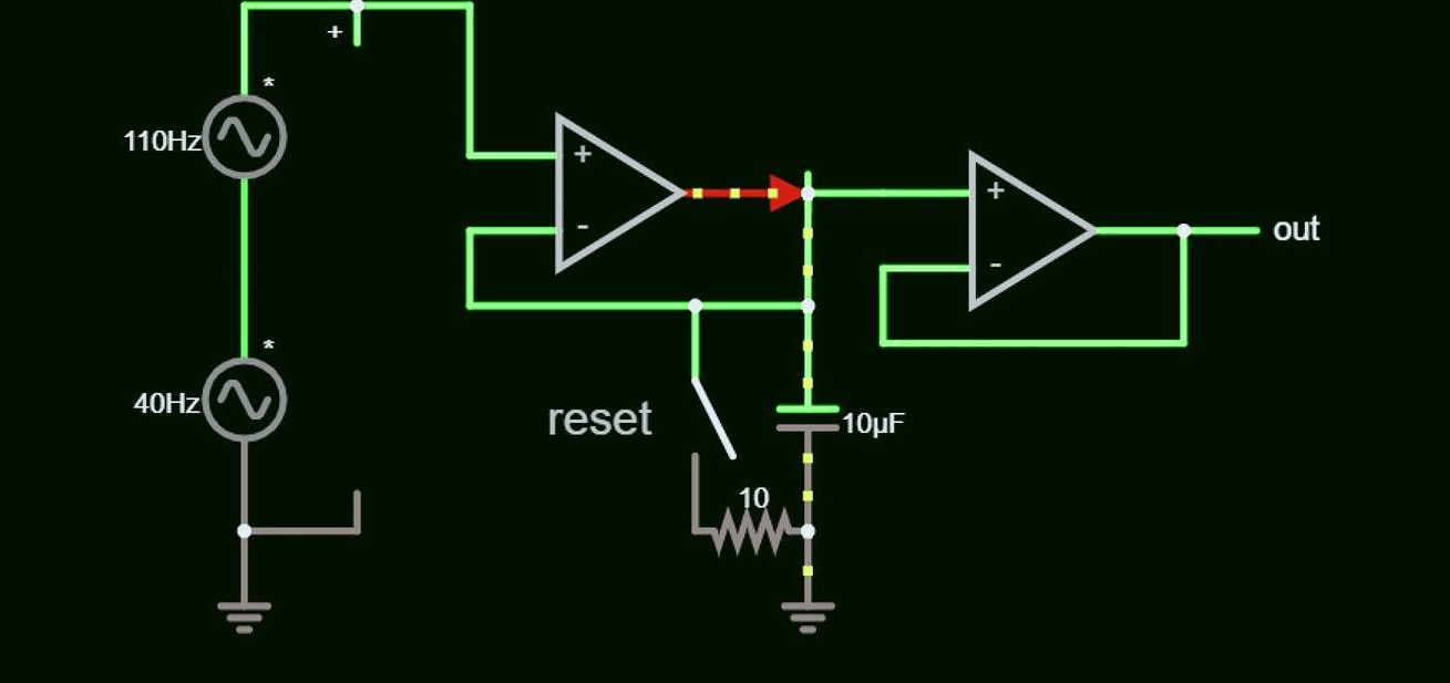
Figure 5: Peak Detector Circuit Diagram
Input Signal
The circuit starts by receiving an input signal, typically a waveform like a sine wave or a pulse. These signals change in amplitude over time, which affects the circuit's response.
Charging Phase
The input signal passes through a diode, which allows current to flow in only one direction. This unidirectional flow prevents backflow and allows the capacitor to charge. A resistor controls the current flow and the charging rate. The capacitor charges to the peak voltage of the input signal for accurate peak detection.
Holding Phase
After charging, the capacitor holds the peak voltage. This retention phase acts like short-term memory, keeping the peak value even if the input signal drops or fluctuates. The diode blocks reverse current, preventing the capacitor from discharging and maintaining a stable reference voltage.
Output
The voltage across the capacitor represents the highest voltage reached by the input signal. This stable voltage is available for output as long as the input signal does not exceed the previously detected peak. The output can be used as a reference voltage or to trigger other circuits when specific signal thresholds are met.
Types of Peak Detectors
Peak detectors are best in signal processing, capturing extreme values of waveform amplitudes. The type of peak detector chosen depends on the application's specific needs, particularly the polarity of the signal peaks.
Positive Peak Detector
The positive peak detector captures the highest points of an input signal. It is used in applications where the maximum positive amplitude, such as audio processing and radio frequency modulation. The circuit includes a diode that conducts during positive signals, charging a capacitor to the peak voltage. This voltage is held until a new higher peak is detected.
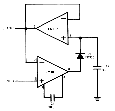
Figure 6: Positive Peak Detector Diagram
Negative Peak Detector
The negative peak detector captures the lowest points of a waveform. It works like the positive peak detector but in reverse, using a diode that conducts during negative signals to charge the capacitor. This type is important in applications where the lowest amplitude is needed, such as in oscillators and inverting circuits.
Figure 7: Negative Peak Detector Diagram
Peak-to-Peak Detector
The peak-to-peak detector stands out by providing a dual-functionality, capturing both the highest and lowest points of a signal, thus offering a full amplitude range measurement. This is achieved by combining the functionalities of both positive and negative peak detectors in a single circuit. The output of this detector is particularly valuable in applications like digital storage oscilloscopes and signal integrity analysis for high-speed digital transmissions, where the signal's entire dynamic range is a major aspect. The total amplitude variation, or peak-to-peak voltage, is what's needed to precisely calculate signal power and integrity.
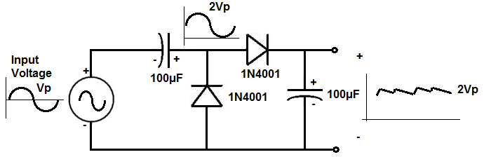
Figure 8: Peak-to-peak Detector Diagram
Peak Detectors Modes of Operation
Peak detectors are powerful tools in signal processing. They operate in different modes to match specific application needs. The two main modes are real-time and sampled peak detection, each tailored for different performance requirements.
Real-Time Peak Detection Mode
Real-time peak detection continuously processes the input signal, ensuring immediate response to changes in amplitude. This mode is required where any delay is unacceptable, like in live audio mixing, where signals must be processed without noticeable lag. The detector quickly identifies the highest amplitude, allowing for real-time adjustments such as dynamic range compression or volume leveling.
Real-time mode depends on fast-responding components, particularly diodes and capacitors, which must rapidly charge and discharge with the signal's changes. This mode is also needed in safety systems, where surpassing a signal threshold triggers immediate actions, such as equipment shutdowns or operator alerts.
Sampled Peak Detection Mode
Sampled peak detection samples the input signal at set intervals rather than continuously. Each sample is analyzed to determine if it represents a new peak, updating the peak value accordingly. This mode is advantageous where processing power and energy efficiency are prioritized over immediate response time.
Sampled mode reduces processing load by not requiring constant signal monitoring. It allows for intervals where the system can perform other tasks or enter a low-power state, making it ideal for battery-operated devices or systems with limited computational resources. Environmental monitoring systems, which track changes over long periods, often use sampled mode to efficiently manage power and processing needs while ensuring accurate peak detection.
Peak Detector Circuit
A peak detector circuit has importance in electronic design, used to capture the highest or lowest values of a fluctuating signal. It typically includes a diode, a capacitor, and a resistor, forming a simple yet effective circuit to capture signal peaks.
Enhancing Circuit Performance with Operational Amplifiers
To enhance a basic peak detector circuit, an operational amplifier (op-amp) can be added. This improves precision and response time. Acting as a buffer, the op-amp provides high input impedance and low output impedance, stabilizing the circuit and accurately capturing the input signal peaks.
Operational Dynamics of the Circuit
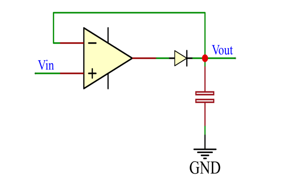
Figure 9: Diagram of a Peak Detector using an Op-amp
When an input signal is applied, the diode allows the capacitor to charge until it reaches the peak voltage of the input signal, becoming the output voltage (Vout). This voltage is stored in the capacitor until the input signal (Vin) exceeds this value, making the diode forward-biased.
If Vin is greater than Vout, the circuit follows the input voltage. When Vin drops below Vout, the diode becomes reverse-biased, stopping the capacitor from charging further. The capacitor holds the peak voltage until the input signal exceeds this stored value again. This dynamic allows the circuit to update and hold new peak values whenever Vin surpasses the previous peak.
Resetting Peak Detector
To precisely track new signal peaks after capturing an earlier one, a peak detector circuit must be reset. In quickly changing signal settings, clearing the stored peak value helps to prepare the circuit for new measurements.
Automated Resetting Using a MOSFET
To reset a peak detector, the stored voltage in the capacitor must be discharged. This can be done efficiently with a Metal-Oxide-Semiconductor Field-Effect Transistor (MOSFET). A reset signal to the MOSFET's gate turns it on, discharging the capacitor quickly to ground. Programmable reset timing ensures the peak detector is ready to capture new peaks immediately. Using a MOSFET adds flexibility and reliability, making it ideal for continuous monitoring in complex electronic systems.
Manual Resetting with a Mechanical Switch
For simpler applications, a manual reset method can be used. This replaces the MOSFET with a mechanical switch. Activating the switch manually discharges the capacitor, requiring physical intervention. It's cost-effective for basic applications, avoiding extra control circuitry. This method adds resilience and user interaction, making it ideal for teaching, prototyping, and situations where automation adds unnecessary complexity.
Peak Detector Waveform
The performance of a peak detector circuit is clearly shown through its output waveform, which indicates the circuit's ability to track signal peaks accurately and quickly.
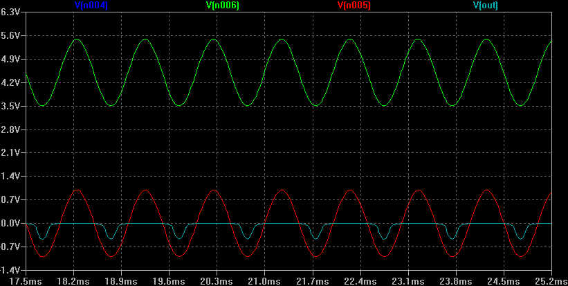
Figure 10: Peak Detector Waveform
Dynamic Response of the Peak Detector
The output waveform of a peak detector rises to match the highest peak of the input signal encountered so far. Once this peak is recorded, the waveform holds this value until a new, higher peak is detected. This holding pattern is good for applications that need continuous peak monitoring, as it ensures the peak value is neither lost nor underestimated during processing.
Acting as a buffer, the op-amp provides high input impedance and low output impedance. This minimizes the loading effect on the input signal and prevents alterations by downstream circuit elements. Consequently, the waveform follows the input signal's peaks more precisely and responds quicker.
Enhancement of Stability and Accuracy
The op-amp's role extends beyond buffering and it also stabilizes the entire circuit. This is needed when the input signal changes rapidly or contains high-frequency components, which could otherwise lead to erratic or inaccurate peak detection. The op-amp ensures the output remains stable and consistent, regardless of the input signal's complexity or variability.
Enhanced stability and accuracy are key in high-performance applications where precise peak detection is needed, such as in digital communication systems, audio processing, and biomedical signal analysis. In these fields, accurately capturing and holding signal peaks directly impacts the effectiveness and reliability of the technology.
Peak Detector ICs
Peak detection ICs are carefully designed to accurately identify the peak values of electrical signals. For example, in audio equipment, peak detectors prevent signal clipping that can cause distortion, preserving audio quality. Similarly, in communication systems, these ICs monitor signal strength, good for adjusting transmitter power and enhancing signal reception.
One example is the PKD01 from Analog Devices. This chip uses advanced tech for peak detection, making it easy to capture peak signal values. The PKD01 is known for being very accurate and reliable, with quick response times and little signal interference. It is also very durable, which makes it perfect for industrial uses where conditions can change a lot. The PKD01 and similar chips do more than just detect peaks, they make electronic systems work better. They reduce the need for extra signal processing hardware, simplify design processes, and improve system reliability. Using these chips helps developers save time and money while ensuring the final product works well.
These peak detector chips have many uses. Besides audio and communications, they are excellent in car systems for managing batteries, medical devices for checking vital signs, and consumer electronics needing accurate signal processing. Each use benefits from the chip's quick and accurate readings, which improve the system's performance and efficiency.
Peak Detector Applications
Peak detectors' capacity to record and store peak signal values makes them valuable in a variety of technical domains. This feature improves the precision and dependability of peak signal amplitude detection in several kinds of industries. Their versatility makes them invaluable in areas such as audio, communications, healthcare, and defense.
Audio Processing
In audio technology, peak detectors ensure sound quality in both professional and consumer equipment. They detect and hold peak audio signal amplitudes, preventing distortion that can compromise audio fidelity. This is especially important in live concert venues and recording studios where sound clarity is required. Peak detectors aid in dynamic range compression, balancing sound output by moderating signals that exceed set thresholds, thus enhancing the listening experience.
RF Communication
In radio frequency (RF) communications, peak detectors capture the peak envelope of amplitude-modulated (AM) signals, and for maintaining signal integrity during transmission. Accurate peak detection preserves the modulation envelope, need for effective demodulation and information reconstruction.
Radar Systems
Radar systems depend on peak detectors to improve detection capabilities. They identify the peak points of radar return signals, determining target position, speed, and other attributes. This accuracy is best for military surveillance, air traffic control, and meteorological monitoring. Peak detectors also enhance radar resolution and reduce signal-to-noise ratios, optimizing system performance.
Medical Instruments
In healthcare, peak detectors are used in diagnostic instruments like electrocardiograms (ECG) and electroencephalograms (EEG). These devices rely on precise peak value detection in physiological signals to monitor heart and brain activity. Peak detectors help identify abnormal peaks and patterns indicating medical conditions, providing accurate data for diagnosis and monitoring. This precision is essential for clinicians, particularly in critical care settings where real-time data can influence treatment decisions.
Spectral and Mass Spectrometry
Peak detectors play a key part in spectral analysis, assisting spectral analyzers in physics and chemistry in identifying the highest light or emission levels within a spectrum. This is need for figuring out what substances are made of, as different elements emit or absorb light at specific wavelengths. In mass spectrometry, peak detectors identify peaks that show different ions' mass-to-charge ratios. By finding the highest peaks, scientists can understand a substance's molecular structure and composition. Thus, peak detectors are key tools in lab analysis.
Limitations and Challenges of Peak Detector
• Diode Forward Voltage Drop
A key limitation in diodes is the forward voltage drop, typically around 0.7V for silicon diodes, which can lead to errors in detecting peak values. Precision peak detectors use operational amplifiers (op-amps) with diodes in their feedback loop to amplify the input signal before it reaches the diode, compensating for the voltage drop and ensuring accurate peak detection.
• Capacitor Leakage
Capacitors can leak, causing them to discharge over time, which affects the detected peak value. The rate of discharge depends on the capacitor's quality. To minimize this, engineers select capacitors with low leakage characteristics, but even high-quality capacitors can degrade over time, impacting peak value accuracy.
• Efficiency Loss from Forward Voltage
The recorded voltage in peak detectors is reduced by the diode's forward voltage, resulting in efficiency loss. Schottky diodes, which have a lower forward voltage drop than silicon diodes, are often used to improve efficiency. However, even Schottky diodes have some forward voltage drop that must be accounted for in precision applications.
• Leakage Current from Holding Capacitor
Leakage current from the holding capacitor can gradually reduce the stored peak value. To counteract this, modern designs use high-quality capacitors with very low leakage currents and may include a refresh circuit to periodically restore the peak value. Despite these measures, leakage cannot be completely eliminated, requiring ongoing advancements in capacitor technology and circuit design for improved performance.
Conclusion
As technology advances, peak detectors are becoming even more precise and reliable, solidifying their importance in electronic design and signal processing. We've highlighted their role in different technological applications. From simple audio improvements to complex radar and medical uses, the ability to accurately capture and hold peak signal values is key to keeping systems running smoothly. Even with challenges like diode voltage drops and capacitor leakage, improvements in circuit design and materials have greatly reduced these issues. Looking ahead, continued innovation in peak detector technology will further boost the capabilities of electronic systems across many industries.
Frequently Asked Questions [FAQ]
1. How does a peak detector work with an op-amp?
A peak detector circuit using an operational amplifier (op-amp) captures and holds the peak value of an input signal. It typically includes an op-amp, a diode, and a capacitor. The op-amp boosts the input signal. When the input signal rises, the diode becomes forward-biased, allowing the capacitor to charge up to the peak value of the input. When the input begins to fall, the diode becomes reverse-biased, isolating the capacitor, which holds (or 'stores') this peak voltage. The op-amp in the circuit ensures that the voltage across the capacitor does not discharge rapidly, thus maintaining the peak value for a longer duration.
2. What is the basic function of op-amp?
An operational amplifier, or op-amp, is designed primarily to amplify an input voltage signal. It takes a differential voltage input and produces a single-ended output that is typically hundreds of thousands of times larger than the voltage difference between its input terminals. Op-amps are used in various applications due to their versatility, including signal conditioning, filtering, or complex mathematical operations like integration and differentiation.
3. What is the difference between peak detector and average detector?
A peak detector and an average detector serve different purposes in signal processing. A peak detector identifies the maximum value of a signal during a specified time interval and holds this value, useful in signal monitoring and modulation applications. In contrast, an average detector calculates the mean value of the signal over a specified period. This average value can be crucial for applications where the overall trend or stability of a signal is more relevant than its instantaneous extremes.
4. What is a peak detector in an op-amp?
In the context of an op-amp, a peak detector is a circuit that uses the properties of the op-amp to accurately detect and hold the maximum value of an input signal. By leveraging the high gain and input impedance of the op-amp, the circuit can respond swiftly to changes in the input signal and maintain the detected peak with minimal loss over time.
5. What is a peak detector with a comparator?
A peak detector that uses a comparator instead of an op-amp operates by directly comparing the input signal with the stored peak value. If the input exceeds the stored value, the comparator switches state, updating the stored peak with the new higher value. This method can be faster and more direct than using an op-amp, with the trade-off of potentially being less precise without the signal conditioning provided by an op-amp.
6. How to find the peak of a signal?
To find the peak of a signal, you can use a peak detector circuit composed of an op-amp, diode, and capacitor, as described earlier. The circuit monitors the input signal and whenever the signal rises to a new maximum, the circuit updates and holds this new value at the output. This method is effective for both periodic and non-periodic signals, and is widely used in audio processing, communication systems, and power monitoring.
7. What is the purpose of the peak detector circuit?
The primary purpose of a peak detector circuit is to identify and hold the maximum value of a voltage signal. This is important in various electronic applications, such as audio signal processing, radio frequency modulation.