HomeBlogTrimmer Potentiometers Guide: Pin Arrangements, Principles of Operation, Uses and Configurations
Trimmer Potentiometers Guide: Pin Arrangements, Principles of Operation, Uses and Configurations
In the field of electronic design, adjusting potentiometers (also known as trimmer potentiometers) play an important role. As a type of adjustable resistor, their main function is to provide precise control of the output signal voltage level. This is a special type of variable resistor designed for fine-tuning electronic circuits. This article aims to deeply explore the definition, working principle, characteristics, and application of trimmer potentiometers in modern electronic engineering.
Definition and Working Principle of Trimmer Potentiometers
Technical Characteristics of Trimming Potentiometers
Symbol Refinement and Types of Trimming Potentiometers
Pinout of a Trimmer Potentiometer
How to Connect a Trimmer Potentiometer
Difference Between Trimmer Potentiometers and Ordinary Potentiometers
Applications of Trimmers
Conclusion
Definition and working principle of trimmer potentiometers
Trimmer potentiometers, essential in electronic design, function as adjustable resistors. Their primary role involves meticulous control of output signal voltage levels, essential for fine-tuning intricate circuit systems. At the heart of this component lies its variable total resistance, a feature that fundamentally alters the effective length of the resistance wire or carbon film. This alteration, achieved through either a rotational or sliding mechanism, facilitates the precise adjustment of the signal voltage coursing through it.
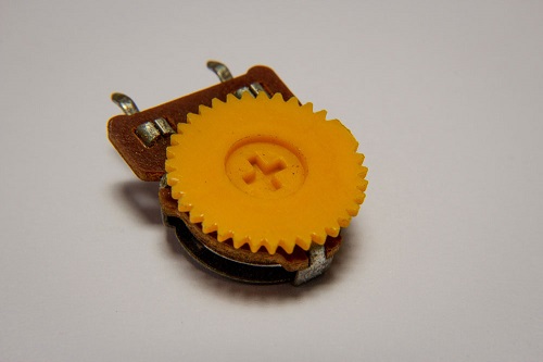
In terms of structure, a trimmer potentiometer typically comprises a rotating or sliding contactor - often referred to as a "brush" - and a resistive body. The brush's movement along the resistive body serves to modify the resistance value. This adjustment, although minute, plays a pivotal role in the overall function of the device.
In practical scenarios, these potentiometers are commonly affixed to printed circuit boards (PCBs). Precision tools, such as screwdrivers, are employed for fine adjustments during testing phases or final product debugging. Their design, which offers more exact control than standard potentiometers, proves crucial in applications like signal amplifier adjustments, sensor output calibrations, or setting analog circuit reference voltages.
Material-wise, the resistive element in trimmer potentiometers typically utilizes either a ceramic metal oxide or carbon composite. Ceramic metal oxides, known for their exceptional thermal stability and high-voltage resistance, are ideal for high-voltage and high-temperature applications. Conversely, carbon composites, owing to their notable wear resistance and stable resistance characteristics, are better suited for scenarios necessitating frequent adjustments. This thoughtful material selection ensures the trimmer potentiometer's reliability and stability across various application contexts.
Technical Characteristics of Trimming Potentiometers
The intricate attributes of trimmer potentiometers manifest in their remarkable versatility and adaptability. Various classifications arise based on materials, including carbon film, metal film, and conductive plastic, each boasting distinct performance and applications. For instance, carbon film trimmer potentiometers gain recognition for their cost-effectiveness and widespread utility. Featuring a slender carbon film deposited on a ceramic substrate, these potentiometers strike a delicate balance between performance and cost, rendering them optimal for applications where stringent budget constraints coexist with the need for moderate accuracy.
The advantages are noteworthy, encompassing a lower temperature coefficient and heightened accuracy, rendering them prevalent in precision electronic equipment that demands steadfast resistance values. The trimmer potentiometer's resistance spectrum spans from 500 ohms to 1M ohms, with lower values finding application in high-current scenarios and higher values commonplace in low-current applications, such as signal processing. This expansive range renders them highly compatible with diverse voltage and current conditions.
Simultaneously, their maximum operating voltage typically caps at 50V DC, aligning with safety requisites and performance standards for most low-voltage electronic apparatus. The 300-volt power rating endows the trimpot with reliable operation in circuits with elevated energy levels. Durability and reliability stand out as hallmarks of trimmer potentiometers, boasting a rotation life of at least 20 adjustments. This longevity proves pivotal in applications necessitating frequent fine-tuning, such as laboratory test equipment or audio conditioners.
In terms of physical attributes, trimmer potentiometers typically feature a more compact design compared to standard potentiometers, aligning with the spatial constraints of contemporary electronic equipment. Presenting in single-turn and multi-turn iterations, users can opt for precision or swiftness as per their requirements. Single-turn models cater to rapid adjustments, while multi-turn variants suit applications demanding heightened precision. Moreover, the adjustable interface design, shaped by the trim pot's rotor, facilitates manual adjustments without necessitating additional tools.
Symbol refinement and types of trimming potentiometers
Trimmer potentiometers, rheostats, and standard potentiometers share basic notations, yet they diverge significantly in functionality and application. Trimmer potentiometers' symbols, derived from the standard potentiometer symbols, incorporate specific modifications. These often include an arrow to denote the adjustment point or special marking lines, augmenting the basic three-terminal symbol to highlight their distinct nature.
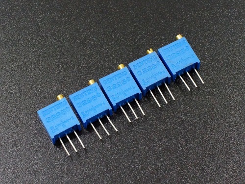
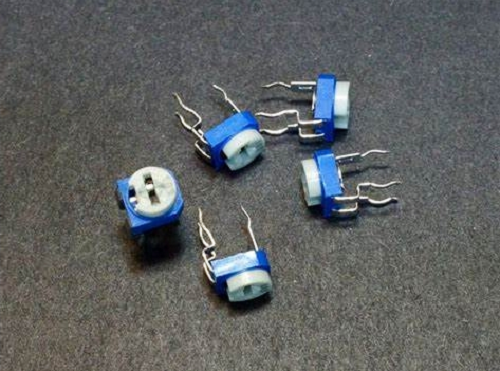
The two principal varieties of trimmer potentiometers - single-turn and multi-turn - each possess unique characteristics and suitable application domains. Single-turn models, often employed for rudimentary circuit adjustments, are crafted for swift and approximate modifications. A single rotation adjusts resistance from its minimum to maximum, making it apt for scenarios where speed trumps precision, such as in certain household devices or basic laboratory apparatus.
In stark contrast, multi-turn trimmer potentiometers, with an adjustment range spanning 5 to 25 turns, enable much more nuanced resistance modifications. These are indispensable in scenarios demanding high-resolution tuning, like in precision measuring tools, professional audio systems, or advanced communication technologies. The multi-turn models excel in high-precision roles by allowing meticulous control and facilitating fine adjustments.
Pinout of a trimmer potentiometer
The trimmer potentiometer's design revolves around three principal pins, each integral to its operational mechanism. These are the clockwise (CW) terminal, the wiper terminal, and the counterclockwise (CCW) terminal.
The CW terminal, linked to one end of the variable resistor, sees an increase in resistance when the knob is turned clockwise. In a circuit, this terminal often connects to the high-voltage side or functions as a control terminal. Its connection—whether to the power supply or signal input—hinges on the specific requirements of the application
Central to the potentiometer's functionality is the wiper terminal. It stands as the most critical terminal, directly tied to the knob's position and offering variable resistance output. The wiper terminal's path through resistive material alters the resistance between the two ends. In practical terms, this terminal serves as the primary point for adjusting voltage or current, evident in applications like volume control or light modulation.
Conversely, the CCW terminal, located opposite the CW terminal, connects to the other end of the variable resistor. Turning the adjustment knob counterclockwise increases the resistance value linked to the CCW terminal. Its role in a circuit varies with design and application, typically connecting to the low-voltage side or acting as an alternate control terminal.
Collectively, these three pins fulfill distinct functions within the trimmer potentiometer, enabling precise resistance control through simple mechanical actions. In the realm of electronic circuit design, grasping the roles of these pins and their circuit implications is crucial for ensuring the potentiometer's effective management of voltage or signal strength as intended.
How to connect a Trimmer Potentiometer
Ensuring the correct connection of the trimmer potentiometer is critical to its efficient operation in the circuit. This process involves more than mere physical installation; it requires an understanding of the potentiometer's electrical characteristics. Key steps and considerations during circuit design and actual installation include:
1. Place the Pins Correctly: In PCB setup, the first step is to align the individual pins of the potentiometer. The CW (clockwise) and CCW (counterclockwise) terminals largely determine the functional direction of the potentiometer within the circuit. Proper placement of these pins is critical for the potentiometer to function as expected.
2. Connect to Power and Ground: Typically, the CW terminal is connected to the positive supply voltage of the circuit, and the CCW terminal is connected to the ground. This setup ensures that when the knob is turned from one end to the other, the potentiometer provides an adjustable voltage range from 0V to the maximum input voltage.
3. Use the wiper terminal: The wiper terminal is an important part of the potentiometer and provides variable voltage output. As the knob is turned, the terminal passes through the resistive material, changing its resistance relative to the CW and CCW terminals. The dynamic interaction of the trumpet with the CW and CCW terminals allows the selection of the voltage output spectrum, which is essential for tasks such as signal level adjustment or establishing a reference voltage.
4. Attention to Circuit Design Details: When designing a circuit, make it a ritual to carefully check the power rating and maximum operating voltage of the potentiometer to prevent exceeding its specified limits. Other factors such as noise level, linearity, and temperature coefficient depend on the nuances of the application.
Difference between Trimmer Potentiometers and Ordinary Potentiometers
In the realm of electronic components, the divergence between trimmer potentiometers and their conventional counterparts is conspicuous, extending beyond mere disparities in size and mounting techniques. These distinctions permeate their design, functionality, and application within electronic circuits.
Dimensions and Fixing Methods:
Trimmer potentiometers, characterized by their diminutive stature, are adeptly suited for seamless integration onto printed circuit boards (PCBs) or perf boards. This compact form factor proves indispensable in contemporary electronic devices where spatial constraints prevail. In contradistinction, ordinary potentiometers, with their larger dimensions, are more commonly ensconced in applications necessitating direct user interaction, exemplified by their role in controlling audio equipment volume.
Precision and Range of Adjustment:
Crafted for meticulous calibration, trimmer potentiometers are available in both single-turn and multi-turn variants. The latter, with its capacity for heightened precision, finds particular utility in contexts demanding fine resolution, such as high-definition settings. Standard potentiometers, predominantly single-turn, cater to more generalized adjustment requirements with a coarser granularity.
Purpose and Utilization:
Trimmer potentiometers find their primary domain in post-manufacturing calibration or nuanced adjustments of electronic apparatus. They ubiquitously grace precision instruments, communication devices, and professional audio systems, where their role extends to regulating voltage, current, or signal gain. In stark contrast, ordinary potentiometers are more ubiquitous in user interface applications, such as modulating light brightness or volume control, where the imperative for precision in adjustments is less pronounced.
Endurance and Consistency:
Trimmer potentiometers, intrinsic to high-precision equipment, undergo engineering with a focus on augmented durability and stability. This meticulous construction ensures that adjustments remain accurate over prolonged periods of use. On the other hand, ordinary potentiometers may prioritize cost-effectiveness and versatility across diverse applications, sacrificing some durability inherent in their trimmer counterparts.
Applications of Trimmers
Trimmer potentiometers are viable electronic components in analog and amplifier-type circuits. To name a few, some application voltage and current control circuits include:
- control or tuning circuits.
- Temperature sensor device.
- Adjust the sound with the volume control knob in the radio.
- An analog input mechanism is used as a control knob.
Conclusion
Through an in-depth analysis of the structural characteristics, technical characteristics, symbol refinement, different types, pin configurations, differences from ordinary potentiometers, and connection methods in practical applications, we can see that adjustable potentiometer Potentiometers play an integral role in electronic circuit design and debugging. Whether in control or tuning circuits, temperature sensor devices, volume adjustments in radios, or analog input mechanisms, adjustable potentiometers offer unique advantages. Their high-precision adjustment capabilities, diverse application scenarios, and improvement in the performance of electronic equipment all highlight their importance in the field of electronic components. Through the analysis of this article, we can not only better understand the technical details of the adjustable potentiometer, but also more effectively utilize this key component in practical applications to improve the performance and reliability of electronic equipment.