The Extensive Guide to High-Pass Filters in Modern Electronics
High-pass filters are influential in electronic design for maintaining signal integrity in various applications, from audio systems to high-frequency data communications. These filters rely on components like capacitors and inductors, whose impedance characteristics are main to their functionality. This article explores how capacitors' impedance aids in allowing high-frequency signals to pass while blocking lower frequencies. It examines the principles of cutoff frequency and how component values affect frequency response in electronic circuits. In addition, the article discusses different filter configurations and advancements, including operational amplifier-based and Butterworth high-pass filters. These insights illustrate how modern technology leverages ultimate concepts to precisely control signal processing. This thorough examination not only details theoretical underpinnings but also emphasizes the practical applications of high-pass filters in improving audio clarity and quality in engineering and other fields.Catalog
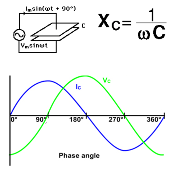
Figure 1: Capacitor's Impedance
The Capacitor's Impedance in Electronic Circuits
Capacitors play a dynamic role in electronic circuits due to their unique impedance properties, especially when designing high-pass filters. The impedance of a capacitor decreases as the signal frequency increases. This means capacitors can block low-frequency signals by presenting high impedance, preventing these signals from reaching the load. By doing so, they maintain the integrity of higher-frequency signals, allowing only those above a certain threshold to pass through.
This behavior of capacitors is not just a passive characteristic; it is a deliberately utilized feature in many electronic devices. Designers exploit this property to enhance performance by focusing on basic signal frequencies and eliminating unwanted lower frequencies. This precise frequency management is a key design strategy, aimed at improving the efficiency and functionality of electronic systems.
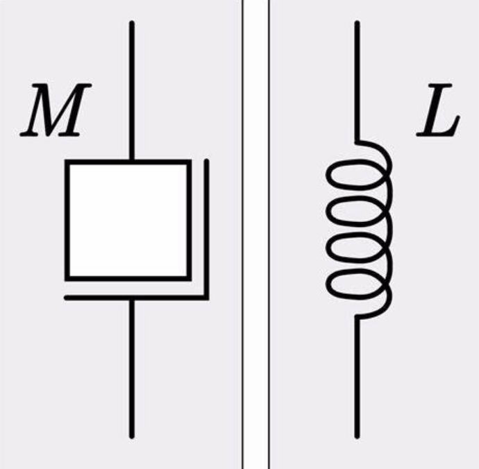
Figure 2: Inductor's Impedance
The Inductor's Impedance in High-Pass Filters
Inductors, unlike capacitors, exhibit decreasing impedance with lowering frequency. This property allows inductors to excel in parallel configurations by diverting low-frequency signals away from the load resistor. In these setups, inductors effectively short out unwanted frequencies, ensuring the voltage primarily drops across components like series resistors (e.g., resistor R1). This makes a clear path for higher frequencies by eliminating lower ones early in the filter circuit.
However, capacitors are often preferred in high-pass filter designs due to their simpler configurations and lower susceptibility to frequency-dependent losses, such as the skin effect and electromagnetic core losses. Capacitor-based designs typically use fewer components, making them less complex and more reliable in high-frequency applications. This distinction between the functional behaviors of capacitors and inductors is settling in designing filters that maintain the clarity and integrity of high-frequency signals, emphasizing the importance of choosing the right component to achieve the desired filter characteristics.
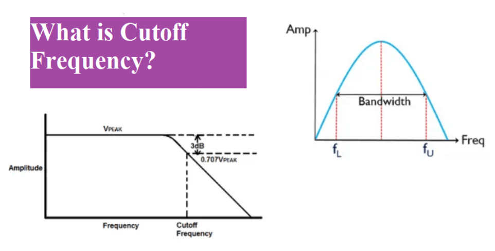
Figure 3: Cut Off Frequency
Cutoff Frequency in High-Pass Filters
High-pass filters are serious components in electronic circuits, designed to allow signals with frequencies above a specified cutoff frequency to pass through while attenuating lower-frequency signals. The cutoff frequency is a key parameter, defined as the frequency at which the output voltage falls to 70.7% of the input voltage, corresponding to the -3 dB point on the frequency response curve. This frequency effectively delineates the passband, where signal transmission is primarily unimpeded, from the stopband, where signal transmission is mostly blocked.
The calculation of the cutoff frequency is based on the values of the resistor (R) and the capacitor (C) in the filter circuit, governed by the formula . This formula is universally applicable to both high-pass and low-pass filters, facilitating consistent performance across various applications and simplifying design processes.
The operational range of a high-pass filter is defined by its cutoff frequency, with frequencies below this threshold being significantly weakened, while those above are transmitted with minimal loss. This characteristic is used for a variety of applications, including audio processing to remove low-frequency noise and hum, communications to filter out low-frequency interference in RF circuits, and instrumentation to eliminate baseline drift in sensor data.
Designing a high-pass filter involves careful selection of resistor and capacitor values to achieve the desired cutoff frequency. This process must account for component tolerances, which can vary and affect the cutoff frequency, requiring precision components for serious applications. In practical applications, high-pass filters are utilized in audio equipment to remove low-frequency rumble and noise, ensuring clear and undistorted audio signals. In RF communication systems, they block unwanted low-frequency signals, allowing only the intended high-frequency signals to pass. Medical devices also benefit from high-pass filters, which eliminate low-frequency baseline wander in ECG and EEG signals for more accurate measurements.
Operation of a Basic High-Pass Filter Circuit
A basic high-pass filter circuit consists of a capacitor and a resistor connected in series. This simple yet effective design manages frequencies efficiently. The capacitor blocks lower frequencies up to a certain cutoff point, acting like an open circuit. Beyond this cutoff frequency, the capacitor's reactance drops significantly, allowing it to act almost like a short circuit. This enables higher frequencies to pass through with minimal resistance to the output.
The capacitor's ability to filter frequencies is settling for high-pass filters. It attenuates frequencies below the cutoff while transmitting higher frequencies effectively. This principle is dynamic in applications needing precise frequency separation, making the basic high-pass filter needed in both simple and complex electronic systems where frequency control is important.
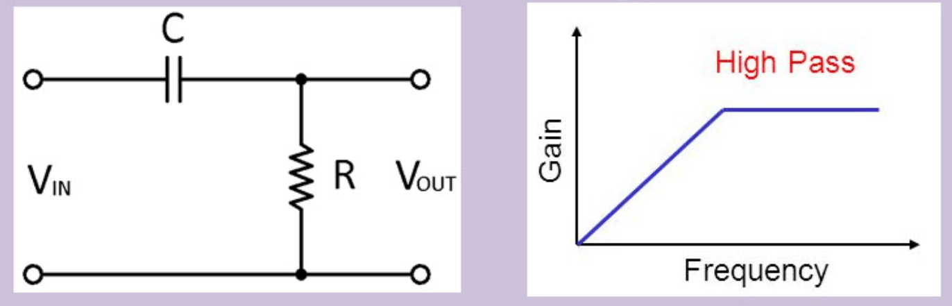
Figure 4: Passive RC High-Pass Filter
Passive RC High-Pass Filter Characteristics
The Passive RC High-Pass Filter operates efficiently without external power, using only a capacitor and a resistor. The capacitor plays a key role due to its reactive properties. It blocks lower frequencies up to a specified cutoff point, acting as an open circuit for these signals. Beyond this cutoff frequency, the capacitor's reactance decreases, allowing higher frequencies to pass through more easily.
The output is taken across the resistor, which stabilizes the voltage and highlights the high-frequency signals allowed by the capacitor. This configuration uses the natural properties of the resistor and capacitor to filter frequencies without additional power. The Passive RC High-Pass Filter is required in applications needing a simple, reliable method to isolate high frequencies from a broader signal spectrum.
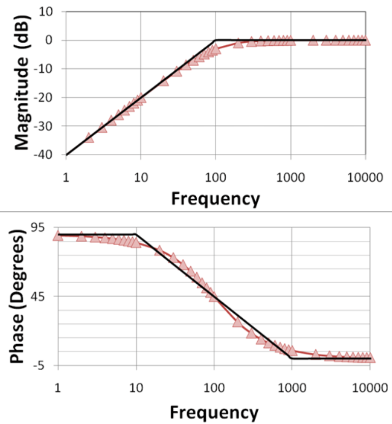
Figure 5: Frequency Response and Bode Plot Analysis of High-Pass Filters
Frequency Response and Bode Plot Analysis of High-Pass Filters
The frequency response of a high-pass filter shows its ability to reduce the gain of frequencies below a specific cutoff point, with a steady -3dB reduction at this threshold. Above the cutoff, the gain increases at a rate of +20 dB per decade (or 6 dB per octave), allowing higher frequencies to pass more effectively. This slope illustrates how the filter emphasizes higher frequencies, clearly distinguishing between the stopband (where frequencies are suppressed) and the passband (where frequencies are transmitted).
The Bode plot graphically represents this response, showing the transition from the stopband to the passband and highlighting the sharpness of the cutoff and the gain increase rate above the cutoff frequency. Additionally, the phase angle shift and bandwidth are important metrics. They indicate how the filter alters the signal's phase across various frequencies and the range over which the filter operates effectively. These factors are used in practical applications, influencing how the filter shapes the signal's output, which is requisite in areas like audio processing and data communications where signal integrity is risky.
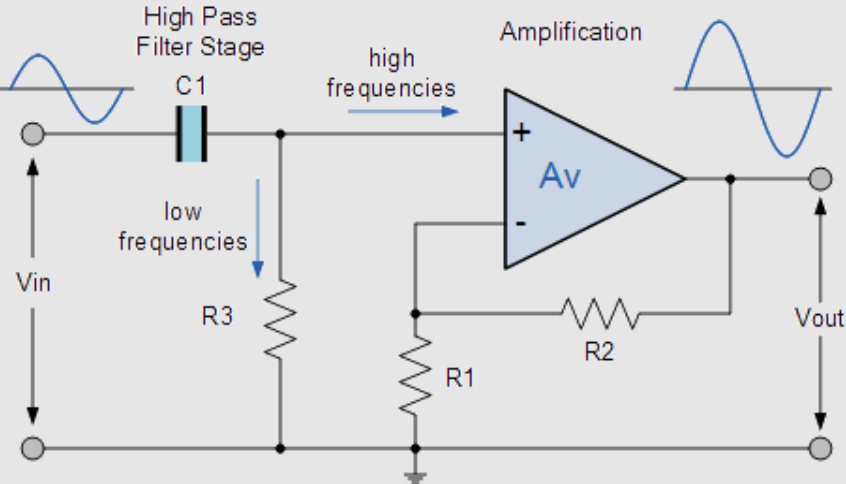
Figure 6: Operational Amplifier-Based High-Pass Filters
Operational Amplifier-Based High-Pass Filters
In advanced filter designs, operational amplifiers (Op-Amps) are used in high-pass filters to greatly enhance their performance. Op-Amp-based high-pass filters differ from passive ones by offering adjustable bandwidth and precise gain characteristics, thanks to the controlled amplification provided by the Op-Amp. This often results in a band-pass effect, where the filter’s frequency response is finely tuned according to the specific attributes of the Op-Amp.
This setup allows for detailed control over the frequency response, enabling precise amplification or attenuation of selected frequency ranges. The active nature of Op-Amp filters not only sharpens the cutoff frequency but also stabilizes the filter’s performance against variations in load and supply conditions. These features make Op-Amp-based high-pass filters ideal for applications requiring robust and precise frequency filtering, such as audio processing systems and signal conditioning modules where maintaining signal integrity is significant.
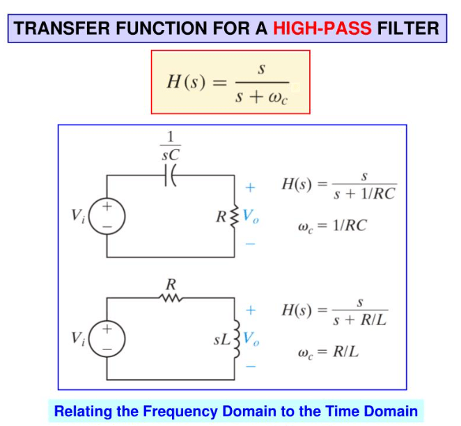
Figure 7: Transfer Function Analysis of High-Pass Filters
Transfer Function Analysis of High-Pass Filters
The transfer function of a high-pass filter explains the circuit’s frequency-dependent behavior, primarily influenced by the capacitor's complex impedance, where 's' is the complex frequency variable and 'C' is the capacitance. This function, derived using standard circuit analysis techniques, shows how the output voltage varies with different input frequencies.
The mathematical model is expressed as , where 'R' is the resistance. This formula not only maps the amplitude but also indicates phase shifts across the frequency spectrum. The roots of the transfer function, real or complex, reveal the system's response characteristics, especially the cutoff frequency, which marks the transition from attenuation to pass-through.
Analyzing and manipulating the transfer function is useful for designing high-pass filters that effectively shape the frequency response for specific applications, such as audio engineering and communication systems. This involves carefully selecting resistor and capacitor values to achieve the desired frequency selectivity and stability, ensuring the filter performs optimally within its operational bandwidth.
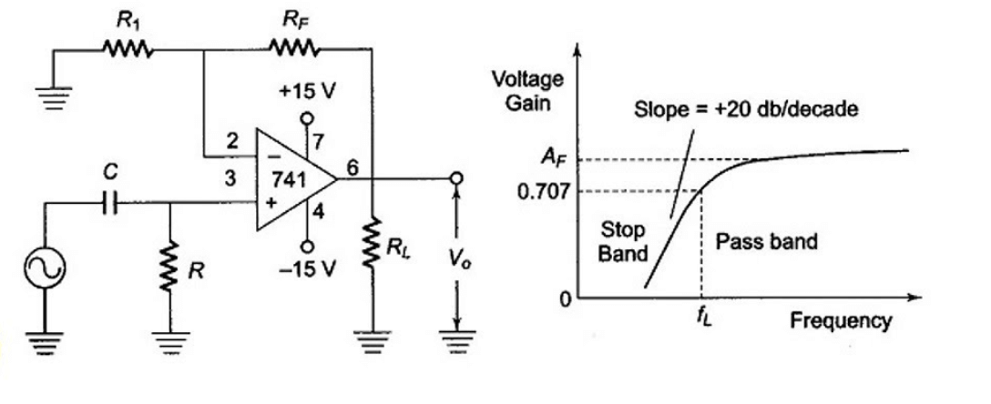
Figure 8: Butterworth High-Pass Filter
Butterworth High-Pass Filter Design and Characteristics
The Butterworth high-pass filter is designed to achieve an ideal filter response with a flat frequency response in the pass band and steep attenuation in the stop band. This is accomplished by cascading multiple first-order high-pass filter stages, which together refine the transition between these bands and ensure a consistently flat response across the pass band.
Designing a Butterworth filter involves deriving the transfer function for each stage and solving these functions systematically. The goal is to align the combined effect of these stages with the desired characteristics of an ideal high-pass filter. The polynomial roots of the transfer function are calculated to ensure maximum flatness within the pass band, hence the term "maximally flat magnitude." This design not only sharpens the cutoff but also minimizes phase distortion across the frequency range.
In practical applications, the Butterworth high-pass filter effectively blocks unwanted low-frequency components while preserving the integrity of frequencies within the pass band. This makes Butterworth filters particularly valuable in audio processing, signal conditioning, and communication systems where clear and accurate frequency delineation is a must.
Utilizing a High-Pass Filter in Audio Mixing
Removing Low-Frequency Clutter: High-pass filters are useful in audio mixing to create a clear and focused sound. They are used to remove low-frequency noises that can mask finer details in the audio. For example, high-pass filters effectively eliminate microphone rumble and ambient HVAC noise. This process is influential for tracks like vocals and acoustic guitars, where clarity is key. By filtering out low-end noise, these tracks become cleaner, allowing more space for bass-heavy elements like kick drums and bass guitars.
Managing Frequency Build-Up: High-pass filters also play a dynamic role in controlling frequency build-up in effects like reverb and delay. By reducing low-end frequencies in these effects, the mix avoids becoming too dense and retains its clarity and airiness. This ensures that each sound remains distinct and the overall mix doesn't become muddy.
Achieving Instrument Separation: Another serious function of high-pass filters is to help separate instruments within the mix. By carefully removing overlapping low frequencies, each instrument can occupy its own unique space. This strategic placement enhances the balance and transparency of the audio, allowing listeners to hear each element without frequency interference. The result is a cleaner, more immersive listening experience.
Applying a High-Pass Filter in Sound Synthesis
Sculpting Sound Characteristics: In sound design and synthesis, high-pass filters are insistent for shaping and refining audio signals. These filters modify the timbre and texture by selectively removing lower-frequency harmonics. This can transform a sound into a thinner, more ethereal version, which is useful for creating delicate or subtle elements in a composition.
Dynamic Application Techniques: Sound designers often employ dynamic applications of high-pass filters. By modulating the cutoff frequency using tools like envelope followers or low-frequency oscillators (LFOs), they can create rich, evolving textures. This technique allows gradual changes in the sound, unveiling or masking different aspects and adding a kinetic feel to the audio landscape.
Enhancing Specific Harmonics: Another advanced technique involves placing a resonant peak at or near the cutoff frequency. This enhances specific harmonics or frequency bands, allowing designers to highlight particular sonic qualities. It's particularly effective for creating distinctive sound signatures or emphasizing desired attributes in a sound.
Mastering High-Pass Filters: For professionals and enthusiasts in sound design, mastering high-pass filters is a must. These techniques not only enhance the clarity and distinctiveness of sounds but also expand the creative possibilities for crafting unique auditory experiences. Analyzing and leveraging high-pass filters effectively can significantly elevate the quality and originality of audio projects.
Top High-Pass Filter Plugins for Audio Production
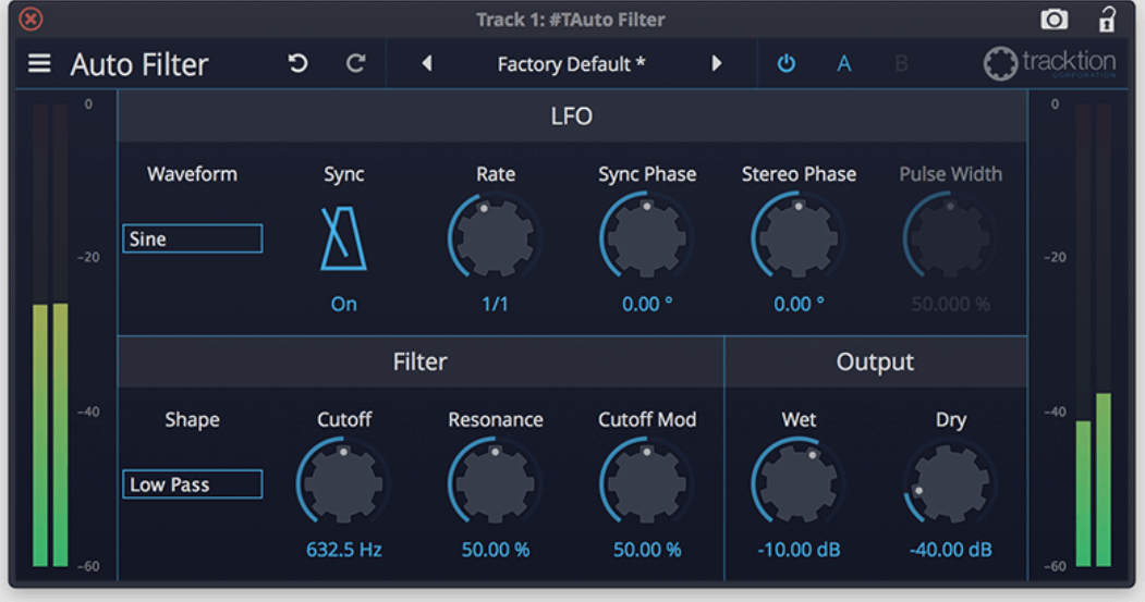
Figure 9: Built-in DAW High-Pass Filter
Most Digital Audio Workstations (DAWs) include high-pass filters, either as standalone features or integrated within multiband EQs. These built-in filters are effective for basic tasks like cutting unwanted low frequencies. Using your DAW's native high-pass filter is cost-effective, eliminating the need for extra third-party plugins for standard frequency removal.
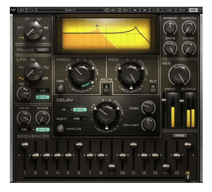
Figure 10: Waves Meta Filter
Waves Meta Filter offers advanced filtering capabilities beyond simple cuts. Priced at $149 but often discounted to below $30, it provides exceptional value. It features various filter shapes, analog modeling, and built-in modulation options like a sequencer, LFO, and envelope follower. These features allow for dynamic and creative filter automation, enhancing both mixing and sound design with high-quality sound output and flexible control settings.
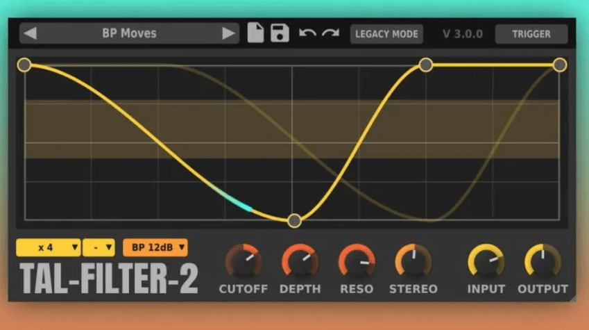
Figure 11: TAL-Filter-2 (Free)
For those on a budget, TAL-Filter-2 is a great free option that doesn’t compromise on functionality. It is easy to use for filter automation and creating various filter effects. It also includes volume and pan automation for added control over the audio signal. Another excellent free alternative is BPB’s Dirty Filter, which offers simple yet effective controls, including high-pass and low-pass filters, adjustable slope settings, and a drive knob for adding character through signal saturation. Both plugins are robust tools for achieving distinctive sound manipulations without any cost.
Other Applications of High-Pass Filters in Audio Systems
|
Applications of High-Pass Filters in
Audio Systems |
|
|
Protection of Speakers |
High-pass filters are used to protect
speakers from handling inappropriate frequencies. By blocking low-frequency
sounds from reaching tweeters, designed for high frequencies, these filters
prevent damage and overdriving. This prolongs the lifespan of the speakers
and preserves sound quality. |
|
Improvement of Sound Clarity |
Ensuring only high frequencies reach the
tweeters, high-pass filters maintain clear and crisp sound reproduction in
the higher range. This separation prevents muddiness, as tweeters are not
efficient at handling lower frequencies, ensuring the audio remains clean and
detailed. |
|
System Efficiency and Power Management |
High-pass filters increase audio system
efficiency by directing appropriate frequencies to each speaker. This allows
speakers to consume less power when producing frequencies they are designed
to handle, reducing overall power consumption and enhancing system
efficiency. |
|
Optimal Use in Crossover Networks |
In complex audio systems, such as home
theaters and professional setups, high-pass filters are integral to crossover
networks. These networks divide audio signals into multiple frequency bands,
sending them to different speakers (tweeters, mid-range speakers, and
woofers). This precise control ensures each speaker operates within its
optimal frequency range, enhancing overall sound quality. |
|
Enhancement of Audio Experience in
Different Environments |
In car audio systems, high-pass filters
help balance sound by compensating for the car's acoustics, which often
emphasize lower frequencies. Filtering out these lower frequencies at the
tweeters provides a clearer and more balanced sound within the challenging
acoustic environment of a vehicle. |
|
Integration with Digital Signal
Processing (DSP) |
In modern audio systems, digital signal
processing (DSP) works with high-pass filters to refine sound output. DSP can
dynamically adjust the high-pass filter's cutoff frequency based on audio
content or the listening environment, enhancing sound clarity and detail in
real time. |
Conclusion
High-pass filters, as explored in this detailed examination, stand as key components in the vast field of electronic engineering, demonstrating significant versatility across a range of practical applications. From their basic form in simple RC circuits to more complex configurations like Butterworth and operational amplifier-based designs, high-pass filters adapt to meet specific demands of signal integrity and frequency management. The underlying principles of impedance, cutoff frequency, and frequency response analysis are settling for designers to manipulate to tailor filters to specific needs. Furthermore, the integration of these filters in systems such as audio mixing, sound design, and even advanced mastering highlights their needed role in refining audio quality and ensuring sound clarity. As technology progresses, the ability to design and implement effective high-pass filters will continue to be integral in advancing electronic and audio systems, ensuring that they not only meet the high standards of modern applications but also push the boundaries of what is technologically possible in signal processing.
Frequently Asked Questions [FAQ]
1. What is the difference between high-pass and low-pass filter?
A high-pass filter allows frequencies higher than a certain cutoff frequency to pass through and attenuates (reduces) frequencies below the cutoff frequency.
A low-pass filter does the opposite, allowing frequencies below the cutoff frequency to pass through while attenuating frequencies above the cutoff frequency.
2. What is the use of high and low-pass filters?
High-pass filters are used to eliminate low-frequency noise or to isolate higher frequencies in signal processing, such as in audio applications to clarify sounds or in digital image processing to enhance edges.
Low-pass filters are used to remove high-frequency noise or to smooth the data in various applications including audio processing for removing hiss, in power supplies to reduce ripple, and in image processing to blur and reduce detail and noise.
3. What is the advantage of using a higher-order filter?
Higher-order filters provide sharper cutoffs between the passband and the stopband. This means they can more precisely separate frequencies close to the cutoff point, resulting in better performance in applications where such precision is analytic, like in audio crossovers or in removing specific frequency bands with minimal impact on adjacent frequencies.
4. What are the advantages of a bypass filter?
The term "bypass filter" could be ambiguous, as it often refers to the ability of a system to bypass a given filter circuit entirely, allowing the signal to pass through unchanged. This is useful in systems where users may want to selectively disable filtering based on different usage scenarios or signal conditions, offering flexibility in how the signal is processed.
5. What are the advantages of high-boost filtering?
High boost filtering is an extension of high-pass filtering, designed not only to pass high frequencies but also to amplify them. It is useful for enhancing details in images, such as sharpening edges, or in audio to increase the clarity and presence of sounds. It enhances the overall contrast or emphasis on high-frequency components that might be imperious in specific contexts, such as in medical imaging or in enhancing speech in a noisy environment.