Sine Wave: Definition, Characteristics and Applications
A sine wave is a basic type of wave in electronics that moves smoothly up and down around a central line. It's very important in both theory and real-world uses, helping people study and control electronic signals. When you look at a sine wave on a screen (like an oscilloscope), you can see details like how tall the wave is (amplitude), where it starts (phase), and how long one full wave takes (period). The smooth movement of the wave makes it easy to see things like timing and coordination in signals. This article looks at sine waves, how they're shown in math and how they're used in electronics, audio tech and power distribution. It talks about how sine and cosine waves are connected, how they're used in spectrum analysis and how they're made in circuits, showing why these waves are important in both theory and practice.Catalog
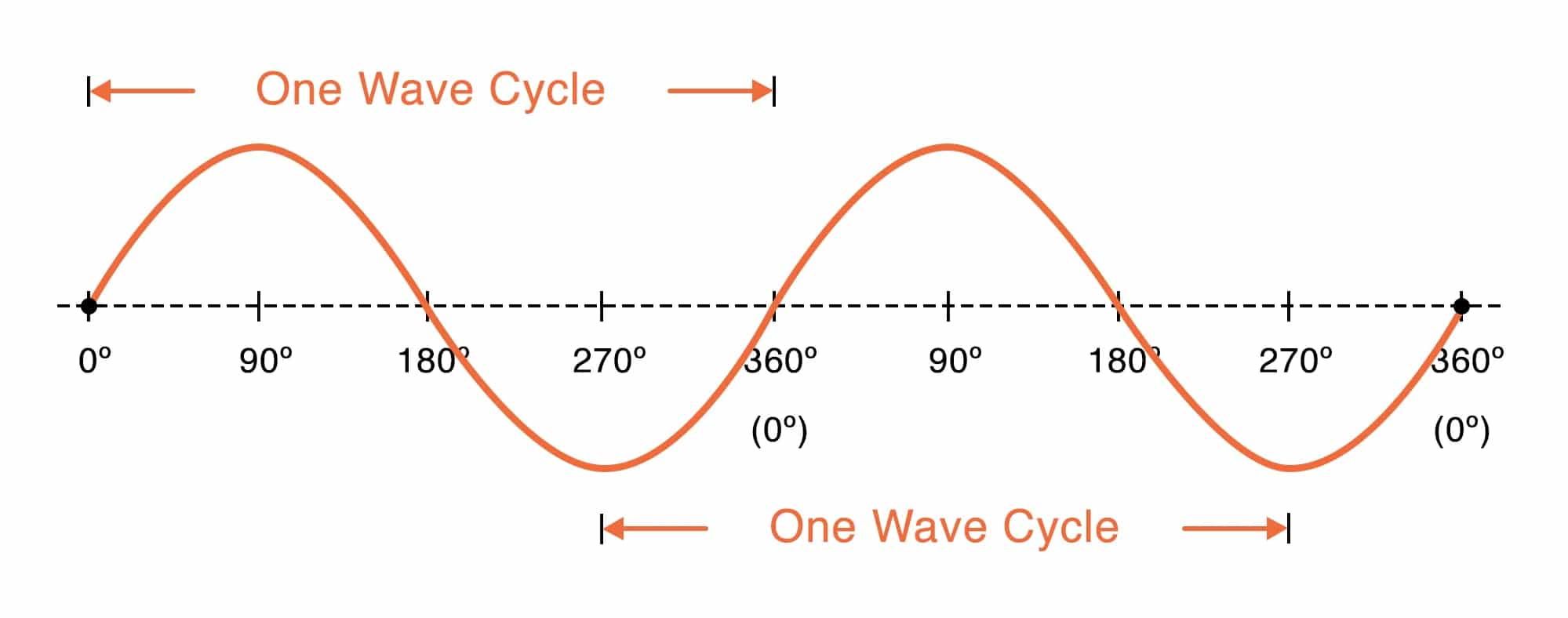
Figure 1: A Sine Wave
Characteristics of a Sine Wave
Amplitude
Amplitude represents the maximum distance the sine wave reaches from its central or neutral position. It’s a measure of how much the signal moves away from its midpoint in both the positive and negative directions. The greater the amplitude, the more energy the wave carries.
In electronic systems, amplitude directly influences signal strength. For example, in power supplies, higher amplitude affects how alternating current (AC) is converted to direct current (DC). Devices such as transformers and voltage regulators use amplitude to control and manage power flow efficiently. Engineers often look at peak-to-peak voltage, measures the distance between the highest and lowest points of the wave to gauge the signal’s strength and stability. This measurement helps ensure that systems operate smoothly without unwanted distortions.
In audio, amplitude controls how loud a sound is. A larger amplitude means a louder sound while a smaller amplitude results in a quieter one. This concept is also good in broadcasting and telecommunications, where strong amplitude helps maintain clear signal transmission over distances.
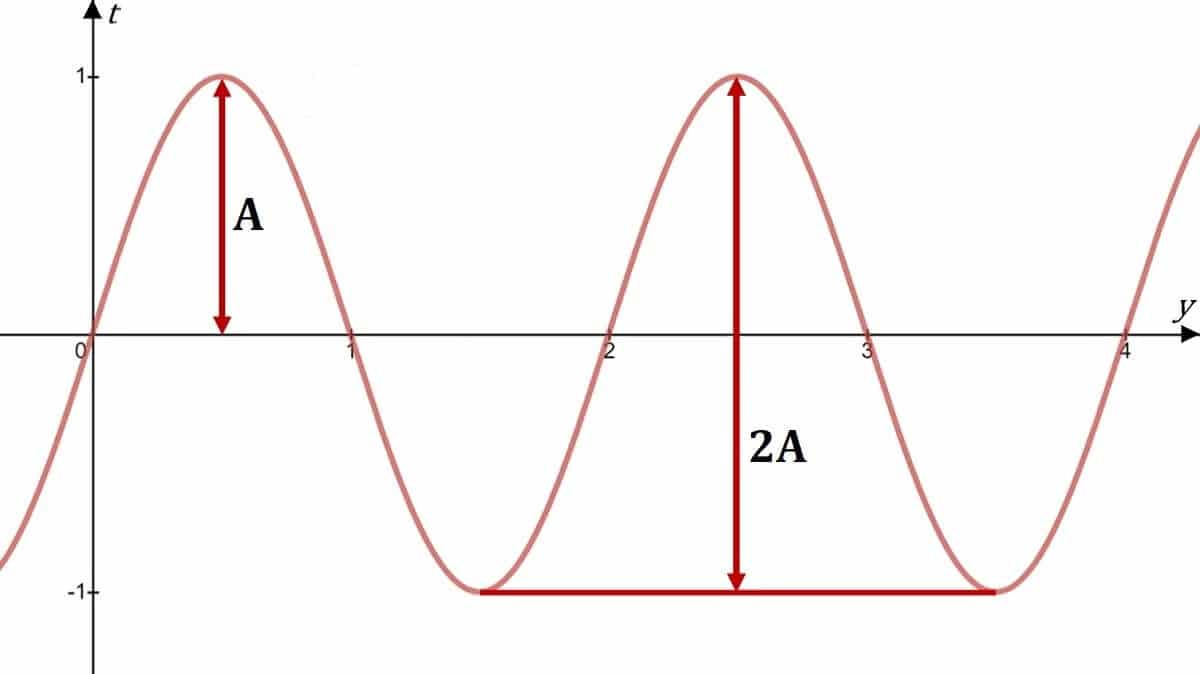
Figure 2: Sine Wave Amplitude
Time Period
The time period, labeled as T, is the duration it takes for the sine wave to complete one full oscillation. This cycle measured from one peak to the next. The time period is inversely related to frequency, meaning as the time period gets shorter, the frequency increases (f = 1/T).
Understanding timing is important in electronic circuits because precise timing ensures everything works smoothly. For example, digital devices use clock signals based on sine waves to control when data is sent or processed helping components communicate properly.
In communication systems, timing helps in sending and receiving signals, like in FM radio, where stable timing prevents signal issues. Similarly, in alternating current (AC) power systems, the timing controls how often the voltage switches direction, usually 50 or 60 times per second, depending on where you live, affecting how appliances work.
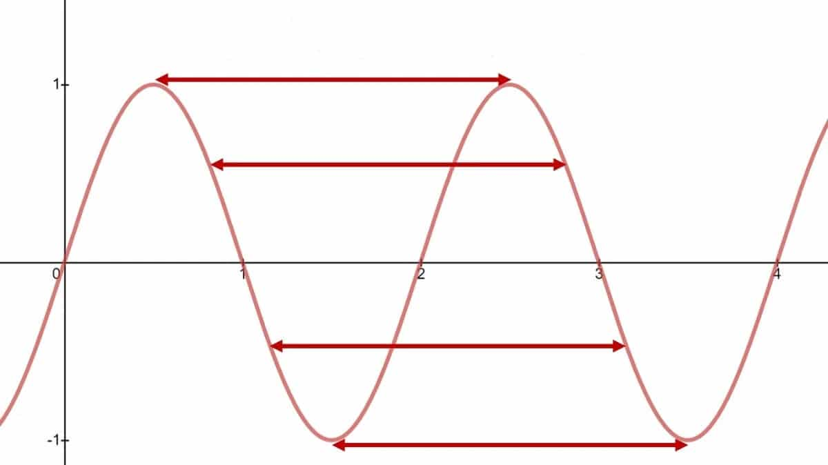
Figure 3: Sine Wave Time Period
Phase
Phase describes the position of the sine wave at any given moment during its cycle, measured in degrees (°) or radians (π). A full cycle equals 360° or 2π radians. If two waves with the same frequency have their peaks and troughs aligned (in phase) they can amplify each other, leading to constructive interference. Conversely, if one wave’s peak aligns with the other's trough (out of phase) they can cancel each other out causing destructive interference and reducing the signal’s strength.
In data transmission, phase is used to encode information. Techniques like Phase Modulation (PM) or Phase Shift Keying (PSK) alter the phase of a carrier wave to represent data. Each phase shift stands for a different data symbol, allowing for efficient digital communication.
In AC power systems, the relationship between voltage and current phases is important for efficient energy transfer. In three-phase power systems, three sine waves are offset by 120° to ensure smooth power delivery. Phase misalignment in such systems can lead to poor efficiency, overheating, or equipment failure.
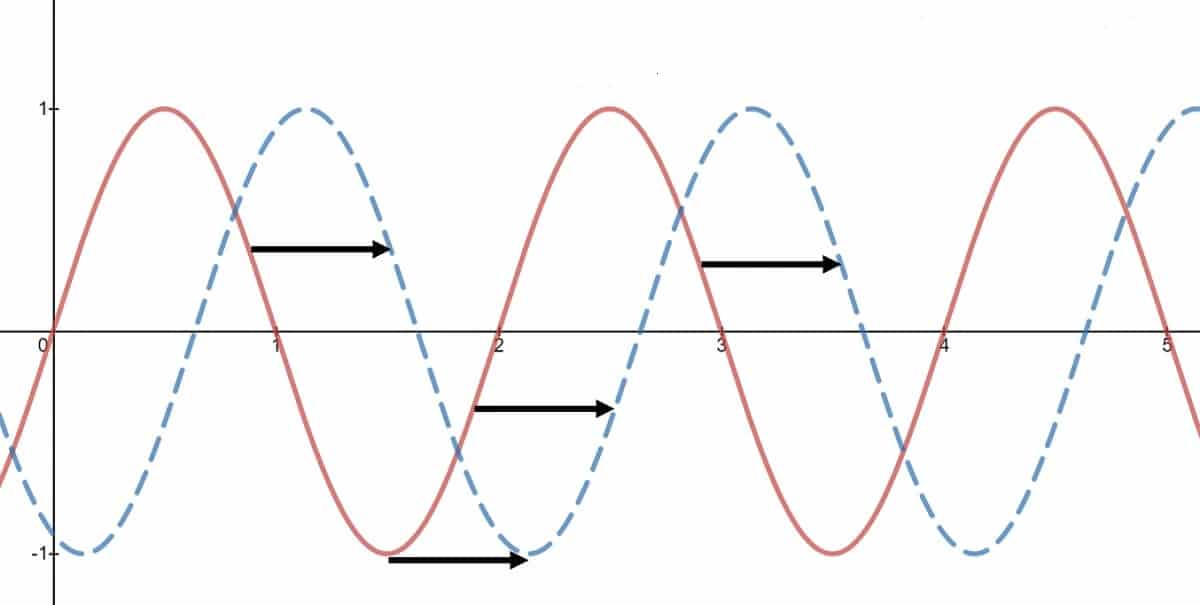
Figure 4: Sine Wave Phase
Sound of a Sine Wave
A sine wave produces a pure, smooth repetitive oscillation. It generates a clean tone, defined by a single frequency, without any added harmonics or overtones.
This clarity makes it a standard reference in audio testing and tuning as it provides a clean, unmodified sound and making it easier to check the performance of speakers, microphones, amplifiers and other equipment. Any distortion or irregularities stand out clearly against the clean sine wave, helping identify hidden issues.
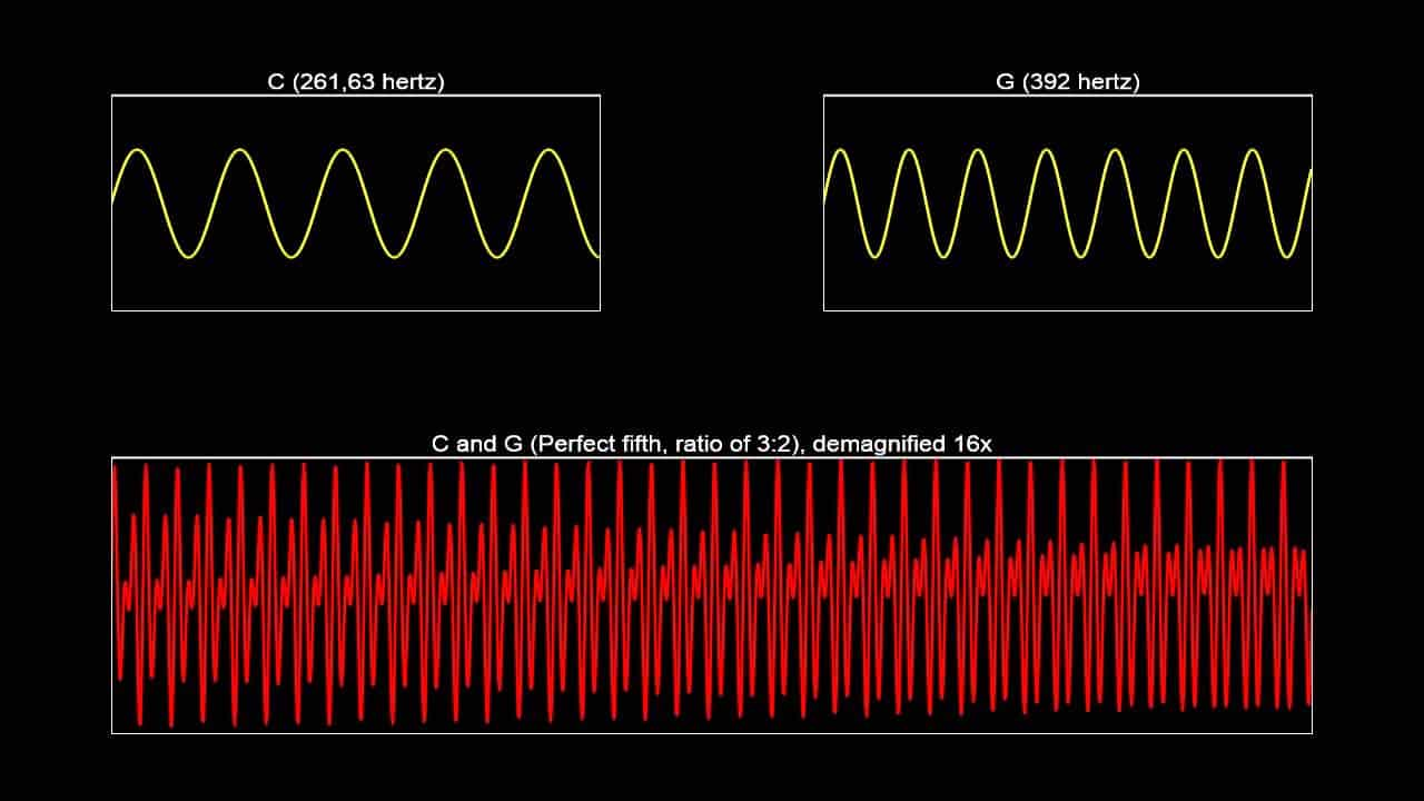
Figure 5: A Sound Waves
Electrical Sine Wave Formula
The sine wave is mathematically represented by the equation:
![]()
In this equation:
• ![]() is the amplitude, showing the wave's maximum height.
is the amplitude, showing the wave's maximum height.
• ![]() is the angular frequency, determining how fast the wave oscillates through its cycle.
is the angular frequency, determining how fast the wave oscillates through its cycle.
• ![]() is the phase, which sets the wave’s starting point at time t = 0.
is the phase, which sets the wave’s starting point at time t = 0.
This formula connects the theoretical side of sine waves. The angular frequency, calculated as 2π times the signal frequency, controls how quickly the wave repeats itself. Phase helps compare different waves and align them in systems requiring precise synchronization.
Sine and Cosine Wave Relationship
Sine and cosine waves are closely related with the main difference being that the cosine wave is just a sine wave shifted by 90 degrees (or π/2 radians) along the horizontal axis. This small shift is important in many areas like physics, engineering and signal processing. If you were to graph them, you'd notice that both waves have the same shape but they're moved over a bit. The sine wave starts at zero and rises to its first peak while the cosine wave starts at its highest point.
A major use of sine and cosine waves is in alternating current (AC) electricity. In AC systems, voltage and current often follow these wave patterns with one being a sine wave and the other a cosine wave. The phase shift between them is important for understanding how power is transmitted and used. For example, this phase shift affects the power factor which measures efficiency in electrical systems.
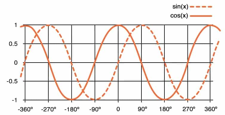
Figure 6: Sine and Cosine Waves
Sine Waves in Spectrum Analysis
In signal processing, sine waves hold a unique position due to their inherent purity. Unlike other waveforms that contain multiple frequencies or harmonics, a sine wave consists of a single, isolated frequency. When a signal is devoid of harmonics or distortion, it can be transmitted, received, and analyzed with minimal interference, ensuring the accuracy and reliability of data transmission.
One of the most powerful methods for analyzing signals is Fourier analysis, which allows complex signals to be broken down into a combination of sine waves. Even complex and irregular waveforms like square or triangular waves can be broken down into a combination of sine waves with different frequencies, sizes and timings.
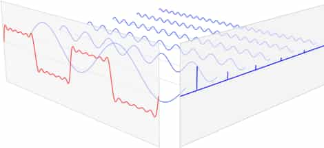
Figure 7: Fourier Analysis
The decomposition of signals into sine waves is valuable in spectrum analysis. When engineers are tasked with analyzing a signal that contains multiple frequency components, Fourier analysis can separate these components, revealing hidden patterns or distortions. This is useful in fields such as telecommunications, radar and audio engineering, where the ability to discern specific frequencies in a complex signal can lead to improved performance and clarity.
Understanding how complex waveforms are made from sine waves is important for system design and signal processing. For example, square waves are made by adding sine waves at the main frequency and its odd harmonics. This helps engineers create filters to focus on certain frequencies or block unwanted noise. In communication systems, signals can also be viewed as combinations of sine waves, making encoding, transmission, and decoding more efficient. Breaking down signals into their sine wave parts allows engineers to design systems that remove noise or interference, leading to clearer signal transmission.
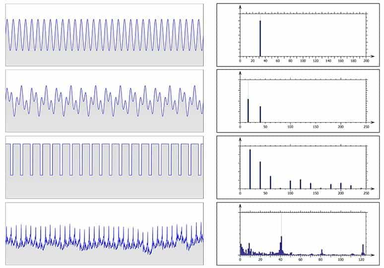
Figure 8: Sine Waves and Their Corresponding Spectrum
Sine Wave Generator Circuit
A sine wave generator relies on an operational amplifier (op-amp) set up in a Wien bridge oscillator circuit. This circuit uses resistors and capacitors to control the sine wave's frequency and keep the output stable. The accuracy of the frequency depends on how stable and good these parts are. Sometimes, a thermistor or diode is added to keep the output steady even if there are changes in temperature or if the components start to wear out. This automatic control helps the generator perform consistently. With modern technology, sine wave generators have become more advanced, producing very pure, low-distortion signals. Many now use digital parts or microcontrollers to precisely control the frequency and amplitude.
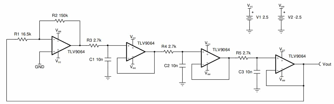
Figure 9: Sine Wave Generator Circuit
Pure Sine Wave vs. Modified Sine Wave
A pure or true sine wave closely replicates the type of power that utility companies provide to homes and businesses. Its smooth and continuous oscillation makes it ideal for running nearly any electrical device. The wave rises to a peak, smoothly falls back down and crosses zero in a steady and predictable rhythm. This consistent flow of energy is what allows sensitive electronics to function properly without disruption.
A modified sine wave doesn't have the same fluid motion. Instead, it simulates a sine wave by producing a series of sharp, stepped waveforms. The pattern jumps quickly to a high positive voltage then drops suddenly to zero and swings just as sharply to a negative voltage. This creates a choppier, more abrupt waveform, spending minimal time near zero. As a result, the power it delivers is less smooth and can cause issues for certain devices.
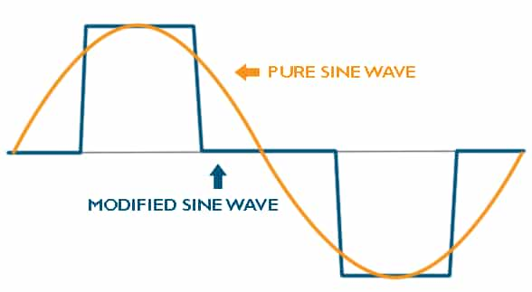
Figure 10: Pure Sine Wave vs. Modified Sine Wave
|
Category |
Pure Sine Wave Inverter |
Modified Sine Wave Inverter |
|
Device Compatibility |
Works with all AC-powered devices,
including complex electronics. |
May struggle with complex electronics,
microwaves, printers and medical equipment. |
|
Performance & Efficiency |
Ensures stable operation and consistent
power flow, preventing glitches. |
Can cause inefficiencies and poor
performance in sensitive devices. |
|
Noise & Heat |
Operates quietly and stays cool with
smooth power delivery. |
Can cause devices to be noisier and
generate more heat, reducing lifespan. |
|
Cost |
More expensive due to advanced design and
smooth power output. |
More affordable, simpler design but less
capable for sensitive devices. |
|
Applications |
Ideal for sensitive electronics like
computers, medical equipment and variable-speed tools. |
Suitable for basic devices like lights,
fans and kitchen gadgets but not ideal for sensitive equipment. |
Conclusion
The sine wave is more than just a math concept, it plays role in electronics, audio engineering and signal processing. Studying its features like amplitude, period and phase helps us understand how it works and how it's used. Sine waves are excellent in designing things like sine wave generators and power systems, showing their importance in today's technology. The difference between pure and modified sine waves shows why accuracy is required for devices to work properly. By learning about sine waves, we can continue to improve and create new technologies.
Frequently Asked Questions [FAQ]
1. Why is electricity a sine wave?
Electricity is represented as a sine wave because of how it is generated in power plants. When mechanical energy is converted into electrical energy through generators, the rotation of the coils within a magnetic field naturally produces alternating current (AC) in the form of a sine wave. This occurs because the voltage and current vary sinusoidally with the rotation of the generator’s armature, reflecting the most efficient way to convert rotary motion into electrical energy. The shape of the sine wave is a direct consequence of this uniform circular motion, making it a natural output of the generation process.
2. What is sine wave in digital signal processing?
In digital signal processing (DSP), a sine wave serves waveform used in the analysis and synthesis of other signals. It is good for Fourier analysis, where complex signals are decomposed into simpler sinusoidal components. This decomposition allows for easier manipulation and understanding of the signal for various applications like filtering, compression and noise reduction. In DSP, sine waves are often used to test systems, analyze filter behaviors and simulate signals.
3. Why it is called sine wave?
The term "sine wave" is derived from the mathematical sine function, describes the wave's shape. This terminology comes from the trigonometric sine function which historically was developed to study angles and ratios in right triangles and circles. The graph of the sine function over time perfectly describes the oscillation of both voltage and current in an AC system, where the wave peaks and troughs follow the sinusoidal mathematical curve.
4. What is the advantage of sine wave?
The sine wave is advantageous because of its smooth and continuous waveform, makes it the most efficient shape for transmitting energy through power systems. Its uniformity allows for minimal power loss in transmission and is less likely to produce electrical noise and interference compared to other waveforms. This property ensures that electrical appliances and infrastructure operate reliably and efficiently with reduced wear and risk of malfunctions.
5. Which signal is represented by sine wave?
Sine waves represent different signals across different fields, including but not limited to alternating current (AC) in power supplies, sound waves in audio engineering and radio carrier waves in telecommunications. In each context, the sine wave is valued for its pure and unmodulated form, makes it ideal for analyses and applications.
6. Is a sine wave AC or DC?
A sine wave is characteristic of alternating current (AC). Unlike direct current (DC) that flows in a single direction, AC periodically reverses direction. A sine wave graphically represents this periodic change in direction and amplitude over time, making it synonymous with AC in electrical contexts. The alternating nature of the sine wave allows for efficient transmission over long distances, which is why AC is the primary form of electrical supply in residential and commercial settings.