Shunt Resistor: What Is It and How Does It Work?
Shunt resistors, also known as current sense resistors are designed to handle high currents and has resistance in the milliohm range. The main purpose of a shunt resistor is to measure current. When current flows through the resistor, it creates a small voltage drop across it. Today, their use has grown with advancements in electronics. The article sorts shunt resistors into different types, like fixed, adjustable, surface mount, through-hole, and Kelvin, each designed for specific needs and accuracy. It also talks about the materials used, such as Manganin, Constantan, Nichrome, metal foil, and ceramic-metal composites, that chosen for their stable resistance and temperature performance. The article explains how shunt resistors work, how they are made, and their important role in things like protecting circuits and measuring current accurately in advanced electrical systems.
Catalog
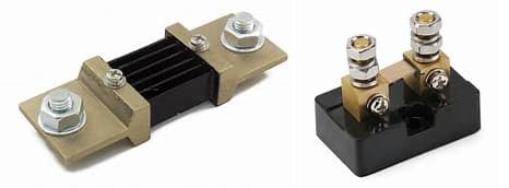
Figure 1: Shunt Resistors
Types of Shunt Resistors
Fixed Shunt Resistors
Fixed shunt resistors are valued for their consistent resistance values. They are used in systems where the current remains relatively stable. Their main advantage is providing reliable performance in these static conditions due to their simplicity and efficiency.
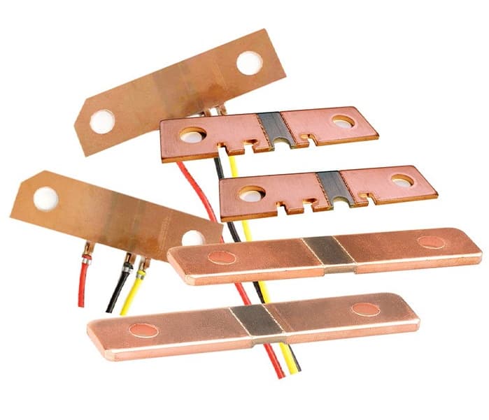
Figure 2: Fixed Shunt Resistor
Adjustable Shunt Resistors
Adjustable shunt resistors allow for the modification of resistance values, and help in accurate current calibration or adjustments in testing scenarios. These resistors are useful in research and development or calibration settings, offering meticulous control over current measurements.
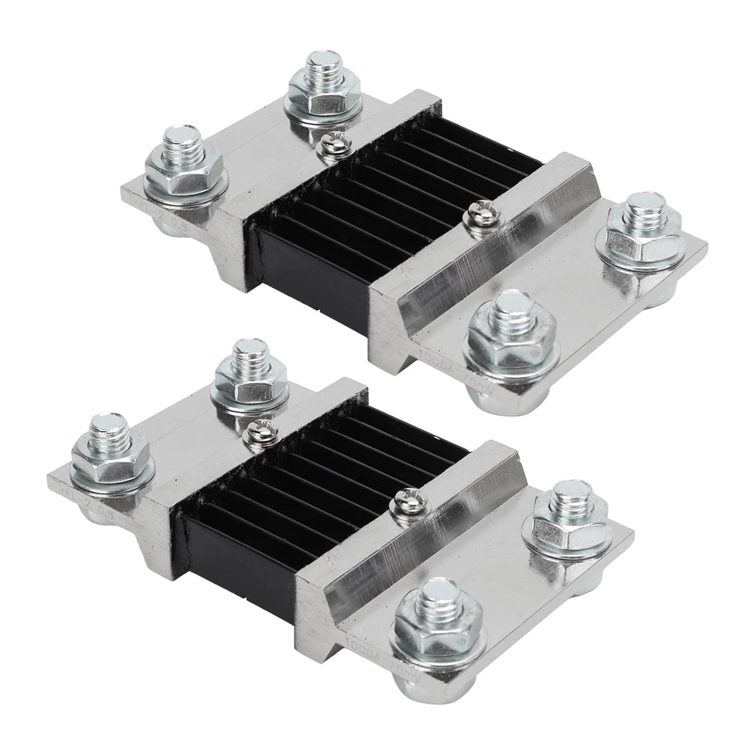
Figure 3: Adjustable Shunt Resistor
Surface Mount Shunt Resistors
Designed for integration into printed circuit boards (PCBs), surface mount shunt resistors, even in their small size, can handle high current levels. They are ideal for compact electronic devices such as smartphones and portable gadgets, supporting streamlined manufacturing and miniaturization.
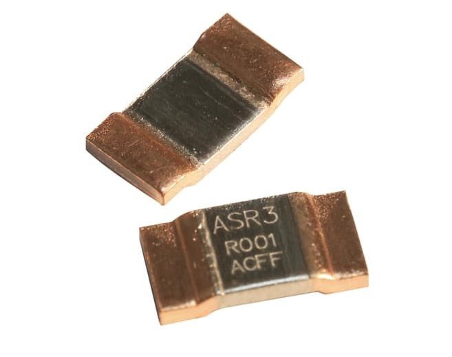
Figure 4: Surface Mount Shunt Resistor
Through-Hole Shunt Resistors
Through-hole shunt resistors are installed by inserting their leads into pre-drilled holes on a PCB and securing them with solder. This installation method improves durability and power handling, making it ideal for tough applications needing strong performance.
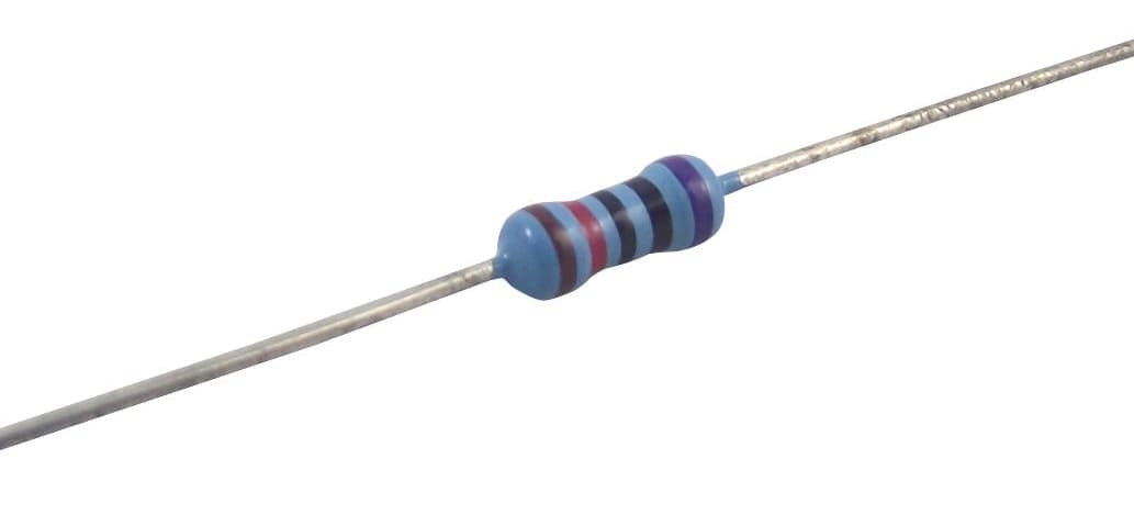
Figure 5: Through-Hole Shunt Resistor
Kelvin (Four Terminal) Shunt Resistors
Kelvin shunt resistors provide precise current measurements by using separate terminals for current and voltage connections. This design reduces errors caused by lead resistance and enhancing measurement accuracy. They are useful in applications needing precise data, like electronic testing and measurement.
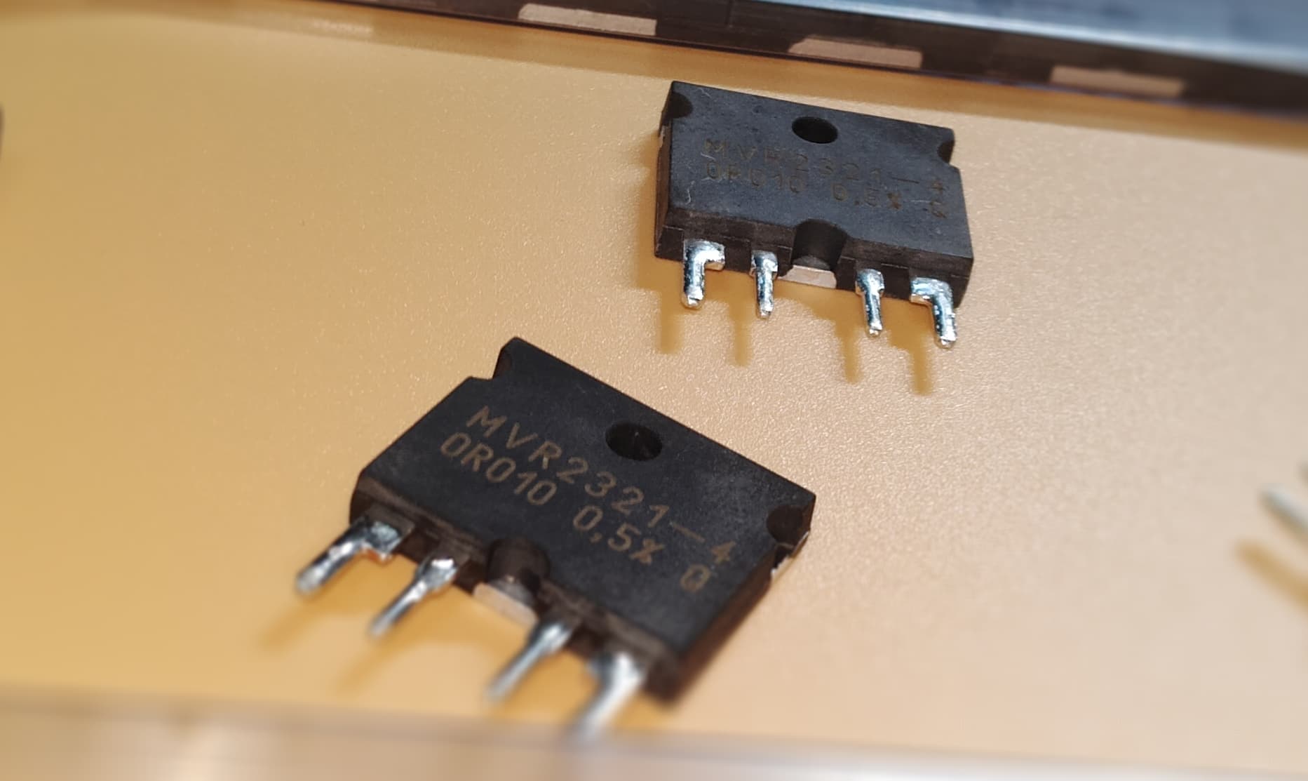
Figure 6: Kelvin (Four Terminal) Shunt Resistor
Materials Used in Shunt Resistors
Manganin
Manganin is an alloy mainly composed of copper, manganese, and nickel. It is favored for high-precision shunt resistors because its resistance remains stable across a wide range of temperatures. This stability comes from its low temperature coefficient, meaning the resistance changes very little with temperature fluctuations. Its consistent performance makes it ideal for applications that require precise measurements.
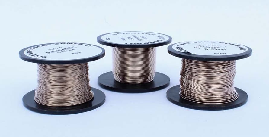
Figure 7: Manganin
Constantan
Constantan, another alloy made of copper and nickel, is known for its very low temperature coefficient. This ensures its resistance stays stable in different environmental conditions. It is an excellent choice for settings with big temperature changes. Precision depends on Constantan's stability, guaranteeing reliable performance regardless of external changes.
Nichrome
Nichrome is an alloy of nickel and chromium, used in shunt resistors for its high resistance and ability to withstand high temperatures. While it has these benefits, its higher temperature coefficient makes it less suitable for precision measurements compared to Manganin or Constantan. However, Nichrome’s resistance to thermal degradation and its mechanical durability make it valuable in high-temperature applications.
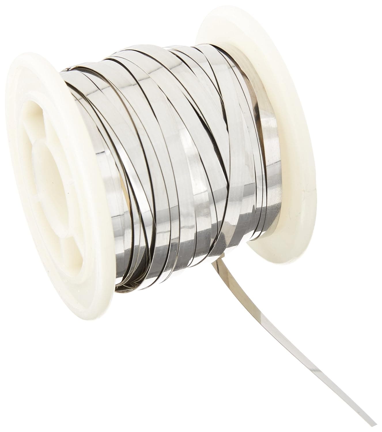
Figure 8: Nichrome
Metal Foil
Metal foil resistors are notable for their extremely low temperature coefficients and exceptional stability. These properties make them perfect for precision applications where even small changes in resistance due to temperature must be minimized. To enhance the performance of major measurement and control systems that demand precision and consistency, designers frequently employ advanced materials engineering.
Ceramic and Metal Alloy
High-power shunt resistors often use a combination of ceramic and metal alloys. This composite material combines the high thermal conductivity and stability of ceramics with the strong resistance characteristics of metal alloys. This mix allows for effective management of high currents, enhancing performance in intense operational conditions and contributing to the durability and reliability of the resistors in demanding power applications.
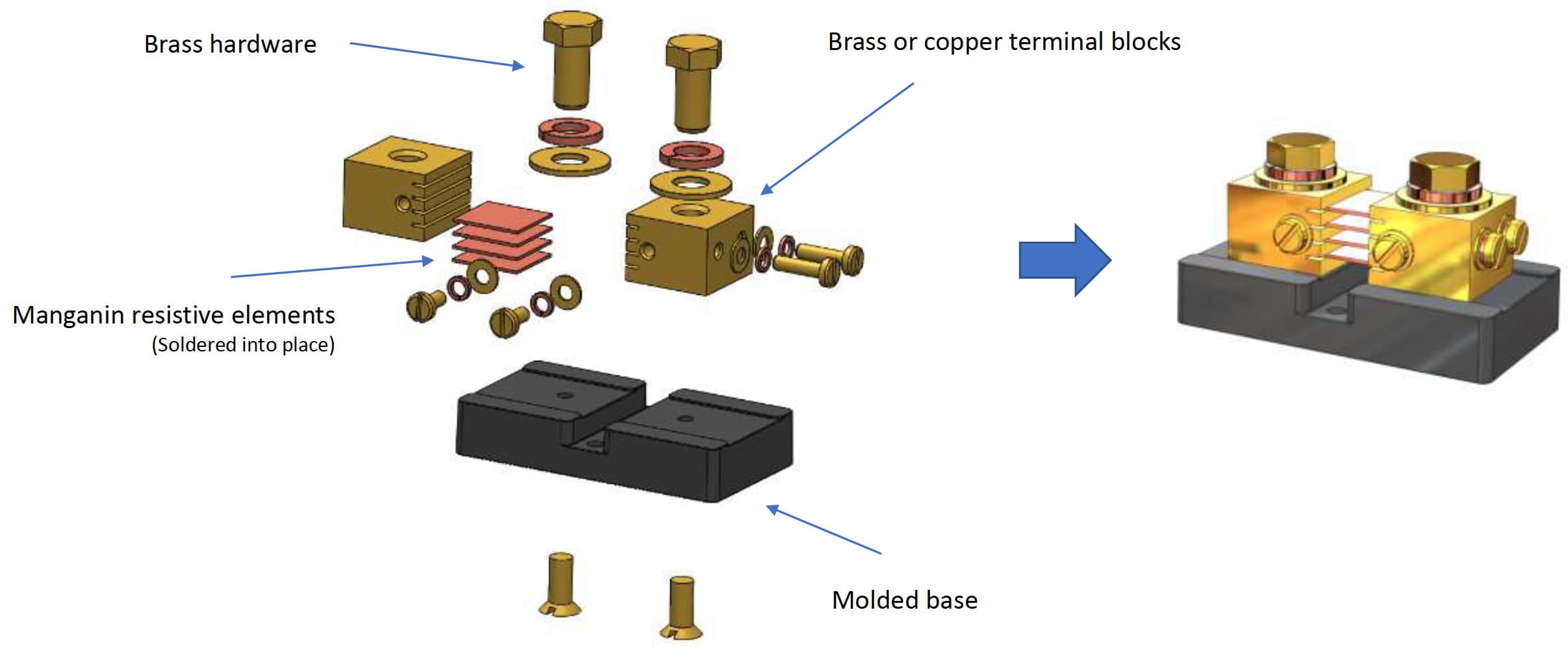
Figure 9: How Are Shunt Resistors Made
How to Build a Shunt Resistor?
To construct a shunt resistor from copper wire for an ammeter, follow these steps to determine the exact wire length required for your desired resistance:
Choosing the Right Wire Gauge
For example, a 10 AWG copper wire has a resistance of about 0.9989 ohms per 1000 feet. However, this can vary based on the wire's quality. Verify the actual resistance per 1000 feet of the wire you plan to use.
Calculating the Required Wire Length
Use this formula to compute the length of copper wire required for your shunt resistor:
![]()
Where:
L is the wire length in feet.
R is the desired resistance of the shunt resistor in ohms.
Rwire is the resistance per 1000 feet of your chosen wire gauge (0.9989 ohms for 10 AWG).
Measuring and Cutting the Wire
After calculating the required length, measure the wire and cut it. It's a good idea to cut the wire longer than calculated to allow for any measurement errors or adjustments during testing.
Forming the Resistor
Depending on your resistance needs and space constraints, you might need to coil the wire. Ensure the coils are spaced out to prevent contact that could cause short circuits.
Attach the wire ends using terminal blocks or soldering. This ensures a firm connection and reliable points for connecting your ammeter.
Testing the Resistor
Before integrating the shunt resistor into any circuit, verify its resistance with an ohmmeter. If the resistance is off from your calculations, make adjustments to achieve the desired resistance.
Integrating into the Circuit
Once you've confirmed the resistor's performance, integrate it into your circuit. Place the shunt resistor so it doesn't alter the circuit's functionality while still providing accurate current measurement.
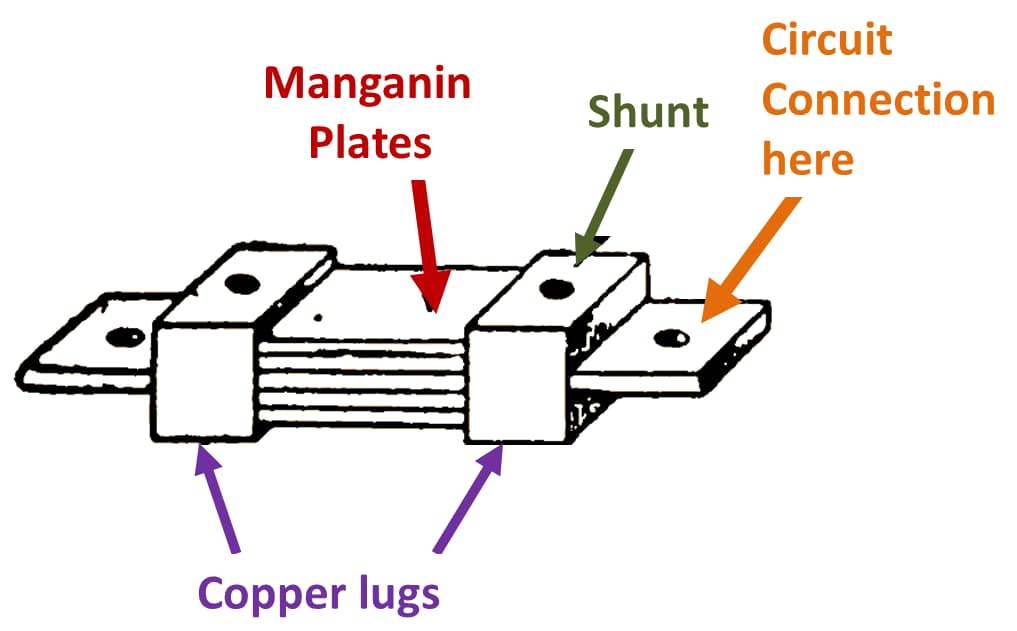
Figure 10: Shunt Resistor Parts
Specifying a Shunt Resistor
When selecting shunt resistors, consider these factors:
Resistance Tolerance: Defines the acceptable variance from the stated resistance, important for precision in sensitive applications.
Temperature Coefficient of Resistance: Indicates how resistance changes with temperature and for determining reliability across different environments.
Power Rating: Specifies the maximum power the resistor can dissipate without damage. Power dissipation, governed by Joule’s law, is influenced by ambient temperature and the resistor’s design.
Managing Power and Temperature: Shunt resistors often include a derating factor, typically 66 percent, for sustained operation beyond two minutes to prevent overheating and ensure longevity and accuracy.
DC Panel Ammeter Shunts
DC panel ammeter shunts are good for measuring current accurately in electrical systems. They improve standard ammeters by letting them measure higher currents than they could handle directly. Shunts do this by diverting a small part of the current through an alternate path to the meter. This method allows the ammeter to give precise readings without being exposed to the full current load, protecting both the meter and the main circuit.
The accuracy of a DC panel ammeter shunt depends on the precise calibration of its resistance. This resistance is important because it controls the voltage drop across the shunt, indicating the amount of current passing through. Proper calibration ensures that this voltage drop accurately reflects the actual current, so the ammeter can convert it into an accurate current reading. Accurate calibration is required because mistakes can cause big measurement errors and affect the device's reliability. DC panel ammeter shunts balance resistance and voltage drop to keep electrical systems safe and efficient.
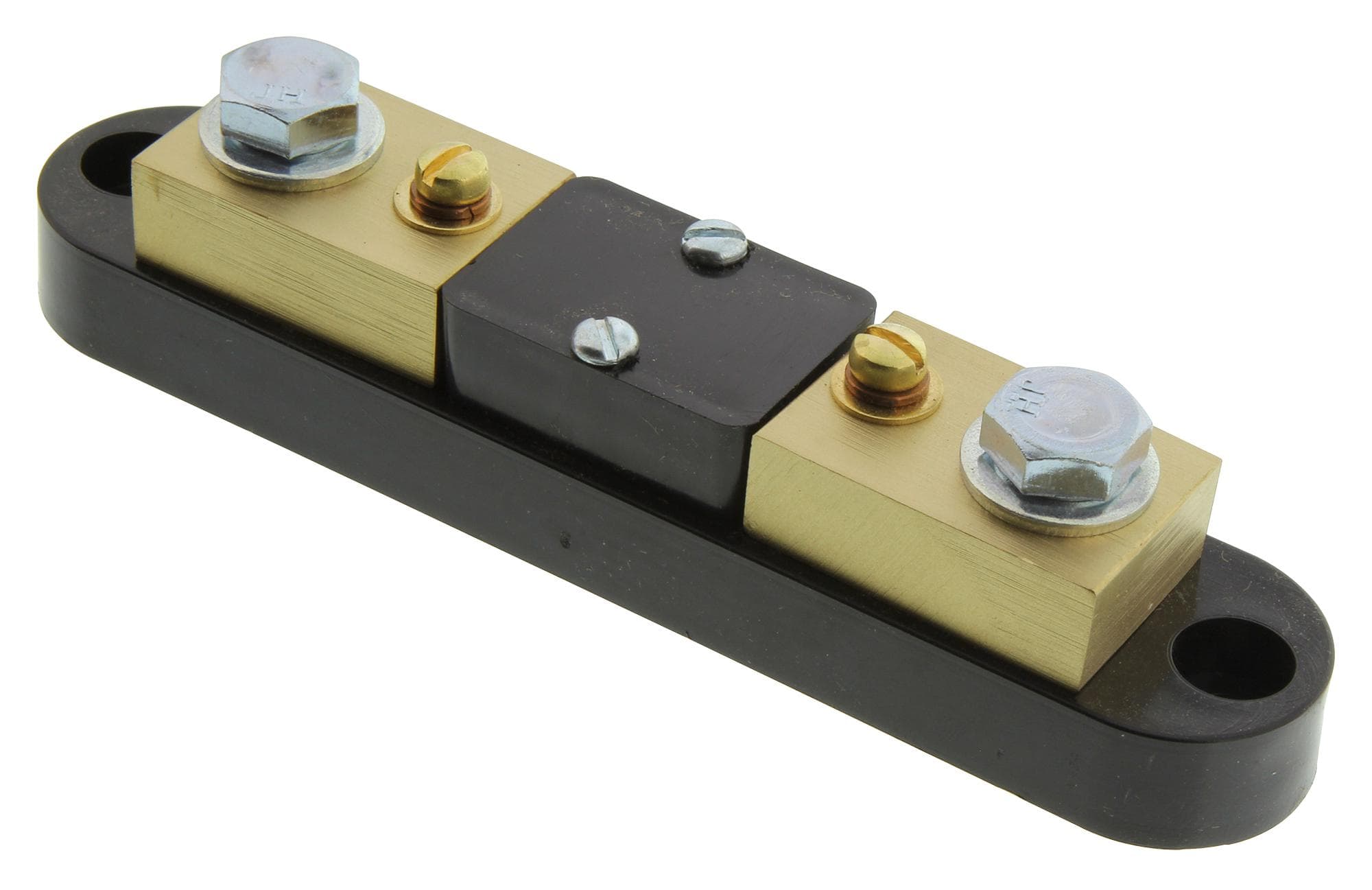
Figure 11: DC Panel Ammeter
How Shunt Resistors Work?
Shunt resistors work by diverting some electrical current away from the main circuit. This "shunting" allows ammeters to measure current without handling the full load, protecting the devices from overloads. They are used to accurately calculate power in watts and direct current (DC). Operating on the principles of Ohm's Law ![]() , where V is the voltage across the resistor, I is the current in amperes, and R is the resistance in ohms, shunt resistors enable exact current calculations.
, where V is the voltage across the resistor, I is the current in amperes, and R is the resistance in ohms, shunt resistors enable exact current calculations.
Consider a shunt resistor with a resistance of 0.002 ohms: it will exhibit a 0.06-volt (60 millivolt) drop when 30 amperes of current flow through it. By measuring this voltage drop and applying Ohm's Law, the current flowing through the shunt can be determined with high accuracy.
Unlike standard resistors, shunt resistors are engineered to maintain precision even at very low resistance levels. Their accuracy is often enhanced by using a Kelvin connection, a four-wire method that minimizes errors from connecting lead resistance and sensitivity issues, thus ensuring more reliable measurements.
However, shunt resistors are not impervious to change. They can undergo reversible and irreversible alterations due to mechanical, electrical, and thermal stresses, affecting their long-term stability and potentially changing their resistance. Metrics such as the Temperature Coefficient of Resistance (TCR) and the Power Coefficient of Resistance (PCR) measure how resistance changes with temperature and power dissipation. These changes are expressed in parts per million per degree Celsius (ppm/°C) for TCR and parts per million per watt (ppm/W) for PCR.
Disconnecting the shunt from the sense line and grounding it, the voltage drop is eliminated, allowing the speed controller to operate at full output. This method, however, risks overloading the controller's transistors if the current exceeds their capacity.
Bench testing also needs high-precision shunt resistors. When paired with voltmeters, they provide a safe and accurate means of measuring current flow in circuits, especially in high-current situations. This method offers a safer and more precise alternative to conventional multimeters, making shunt resistors a cornerstone in electrical testing and measurement.
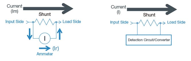
Figure 12: Shunt Resistors Diagram
How to Calculate Current Using a Shunt?
To calculate the current using a shunt, start by understanding Ohm's Law, represented by the equation
![]()
This relationship between voltage drop, current, and resistance is the basic aspect for any circuit analysis.
Begin by substituting the known values into the Ohm's Law equation. For example, if the voltage drop (V) across the shunt resistor is 10 volts and the desired current (I) is 100 amperes, you substitute these values into the equation:
![]()
This equation shows the linear relationship between voltage drop and current through the resistor, allowing us to solve for the unknown resistance (R).
To find R, divide both sides of the equation by the current (100 amperes):
![]()
This calculation reveals that the resistance of the shunt resistor is 0.1 ohms. This value is important because it determines the amount of current that can safely pass through the resistor for a given voltage drop and good for applications needing precise current measurements or limitations.
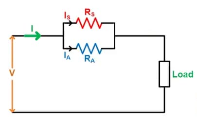
Figure 13: Shunt Resistor Current
Using an Ammeter to Measure Current
To understand how an ammeter measures current, let's walk through a detailed example involving a shunt resistor in a circuit.
For this example, we'll use a shunt resistor with a resistance of 1 mΩ.
Ensure the shunt resistor is connected in series with the circuit where you want to measure the current. This setup ensures that all current in the circuit passes through the shunt resistor.
Use a voltmeter to measure the voltage drop across the shunt resistor. Suppose the voltmeter shows a voltage drop of 30 millivolts (mV).
To calculate the current flowing through the circuit, use Ohm's Law: ![]()
Substitute the measured voltage drop V = 0.030 volts (30 mV) and the resistance R = 0.001 ohms (1 mΩ) into the formula.
![]() = 30 amperes (A)
= 30 amperes (A)
This calculation shows that a current of 30 A is flowing through the circuit.
The measured current of 30 A indicates the electrical current passing through the circuit during the measurement. This example demonstrates the effectiveness of using a shunt resistor for high-current measurements, in various electrical and electronic applications.
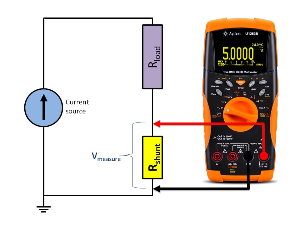
Figure 14: Using a Digital Ammeter to Measure Current
Position of the Shunt in the Circuit for Measuring Current
The accuracy and safety of electrical circuits using shunt resistors for current measurement depend on placing them correctly.
Grounded Side Placement
• Common Practice: Shunts are usually placed on the grounded side of the circuit.
Advantages: This position reduces exposure to high common-mode voltages, protecting the measurement equipment and preventing distorted readings. It minimizes voltage-induced errors, ensuring accurate measurements.
Challenges: There can be leakage currents bypassing the shunt and can lead to underestimated current readings. Engineers can use isolation techniques or voltage dividers to fix this.
Ungrounded Side Placement
• Alternative Method: Placing the shunt on the ungrounded side of the circuit.
Challenges: This introduces the need for additional protective measures.
Solutions: Isolation amplifiers or Hall Effect sensors can be used. Hall Effect sensors measure the magnetic field generated by current flow, allowing for safe, non-contact measurements. While this method improves safety, it also increases complexity and cost.
Safety Checks When Making a Resistance Measurement
Measuring resistance accurately and safely involves a series of important checks. Follow these steps to ensure both precise results and your safety:
|
Step |
Action |
Description |
|
Step 1: Initial Preparations and Power
Disconnection |
Turn Off Power |
Completely switch off the power to the
circuit, to avoid electrical shocks and interference that can affect the
resistance measurement. |
|
Verify Power Disconnection |
Use a reliable tool to double-check that
no current is flowing through the circuit. |
|
|
Step 2: Connection and Configuration of
Measurement Tools |
Connect Ohmmeter Leads Correctly |
Attach the ohmmeter leads to the circuit.
Ensure the positive lead is connected to the positive terminal and the
negative lead to the negative terminal. |
|
Select Measurement Mode |
Switch the ohmmeter to resistance
measurement mode. |
|
|
Adjust Range |
Set the range on the ohmmeter according
to the circuit's expected resistance to get an accurate reading without
overloading the meter. |
|
|
Step 3: Operational Procedures |
Keep Circuit De-energized for Resistance
Measurement |
Do not power the circuit for resistance
measurements. Energizing the circuit can lead to inaccurate readings and
potential damage. |
|
Record Values |
Note the resistance value shown on the
ohmmeter. |
|
|
Turn Off Power Again (if energized
briefly) |
If you need to power the circuit for any
reason (like for current or voltage measurements), ensure it is powered off
again before disconnecting the test leads. |
|
|
Step 4: Post-Measurement Reconfiguration |
Disconnect Test Leads |
Carefully remove the ohmmeter leads from
the circuit after ensuring the power is off. |
|
Restore Circuit Configuration |
If you had to make any changes to the
circuit for the measurement, put everything back to its original state to
ensure the circuit is ready for normal use. |
Applications of Shunt Resistors
Circuit Protection from Overvoltage
Shunt resistors help protect circuits from too much voltage. They are used in special circuits called crowbar circuits that kick in to stop voltage overloads. When high voltage is detected, these circuits create a short circuit, sending the extra current away from sensitive parts. This spike in current activates safety devices like circuit breakers or fuses, keeping the system safe.
Bypassing Faulty Components in Series Circuits
In series circuits, one broken part can stop the whole system from working. Shunt resistors keep things running by providing another path for current around the broken part. This is useful for things like holiday lights, where one bad bulb could make all the lights go out. Shunt resistors ensure the other lights keep working by bypassing the broken bulb.
Reducing Electrical Noise
Shunt resistors improve signal quality by reducing electrical noise, in places with lots of high-frequency disturbances. They work with capacitors to filter out noise, grounding it before it can mess with sensitive parts of the circuit. This keeps things stable and prevents disruptions, ensuring accurate and reliable electrical outputs.
Current Measurement
Shunt resistors are important in ammeters for measuring current accurately. They create a small voltage drop that matches the current flow, allowing technicians to monitor electrical currents without changing the circuit's performance. This method is reliable and accurate, making it great for regular diagnostics and system monitoring.
Overload Protection
Shunt resistors also protect devices from current overload. When the current gets too high, they trigger protective measures in power supplies and other systems. This helps ensure that electrical devices stay durable and work well under different conditions.
Conclusion
Shunt resistors are important in electrical and electronic systems. They ensure safety, control circuits, and measure current accurately. Different kinds of shunt resistors are used for specific needs, from small electronic devices to heavy-duty industrial systems. Materials like Manganin and Constantan are chosen because they are stable and work well in different temperatures, ensuring they perform reliably even in tough conditions. Guidelines for building and using shunt resistors in circuits highlight their many uses, such as protecting circuits, measuring currents and making systems more reliable. As technology advances, shunt resistors are continually improved to handle more complex tasks, making them best components in today's electronics and electrical fields.
Frequently Asked Questions [FAQ]
1. What is the difference between a shunt resistor and a resistor?
A shunt resistor and a standard resistor share the basic function of resisting electric current. However, a shunt resistor is designed for measuring current. It does so by having a very low resistance value and allows it to be placed in parallel with a circuit without altering the total current flow. In contrast, regular resistors can have a wide range of resistance values and are used for various purposes like reducing current, dividing voltages, or setting time constants in circuits.
2. Why do we connect shunt resistance?
We connect shunt resistors to measure the current flowing through a circuit. By placing a shunt resistor in parallel to a portion of the circuit where current measurement is desired, most of the current flows through the shunt due to its low resistance. The voltage drop across the shunt is then measured and used to calculate the current based on Ohm's law.
3. What is the advantage of using shunt?
The advantage of using a shunt resistor is its ability to enable precise current measurement without disrupting the circuit's normal operation. Shunt resistors are designed to have minimal resistance, which ensures that they do not affect the overall circuit impedance. This allows for accurate current monitoring and protecting sensitive components, managing power efficiently, or monitoring and controlling systems.
4. What does a 12-volt shunt do?
A 12-volt shunt in a circuit is used to measure currents in circuits that operate at 12 volts. The term "12-volt shunt" does not refer to the voltage across the shunt itself, but rather to the voltage of the system in which the shunt is used. Like other shunts, it measures the current by allowing a small, measurable voltage drop across itself and can used to calculate the current flowing through it.
5. Are shunt resistors parallel or series?
Shunt resistors are connected in parallel with the circuit or the component of the circuit where the current measurement is required. This parallel connection is required because it allows the shunt to measure the current without carrying the full current load itself. If connected in series, the shunt resistor would affect the total current flow in the circuit that would defeat its purpose of minimally invasive measurement.