Schmitt Triggers in Modern Electronics: Understanding Their Role and Capabilities
The Schmitt Trigger is a main electronic component, first introduced by Otto H. Schmitt in 1937 as a "thermionic trigger". Primarily facilitated through a process known as hysteresis, characterized by its dual-threshold mechanism for signal conversion. The Schmitt Trigger is further exemplified by its two main types: the Inverting and Non-Inverting Schmitt Triggers, each serving distinct operational needs. This article discusses into the intricate workings, applications of Schmitt Triggers, analysis of their operational mechanisms, threshold calculations, practical implications in modern electronic design, particularly highlighting the impact of CMOS in enhancing the performance in low-power applications and their role across different technological domains.
Catalog
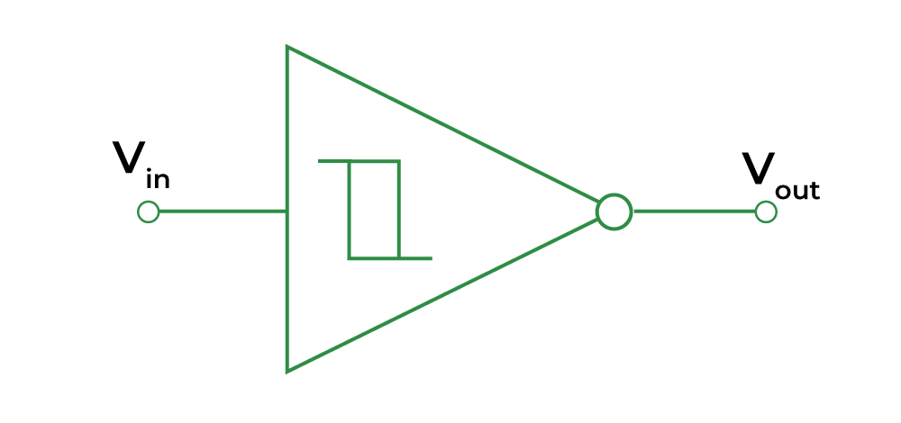
Figure 1: Schmitt Trigger Symbol
Role of Hysteresis in Schmitt Triggers
Schmitt triggers convert unstable analog signals into stable digital outputs. This conversion is achieved through a unique process called hysteresis, which is facilitated by positive feedback. Hysteresis introduces two distinct threshold voltages for transitioning between output states: one for rising input signals and another for falling ones. This mechanism ensures that once the output state changes, it remains stable until the input voltage crosses a different, specifically set threshold. This dual-threshold system eliminates the problem of signal noise or chatter near the threshold level, resulting in more reliable digital signal processing. They simplify circuit design for digital signals and enhance the performance and reliability of systems operating in noisy environments. Schmitt triggers are fundamental in many applications, ranging from simple signal conditioning in consumer electronics to complex digital communication systems.
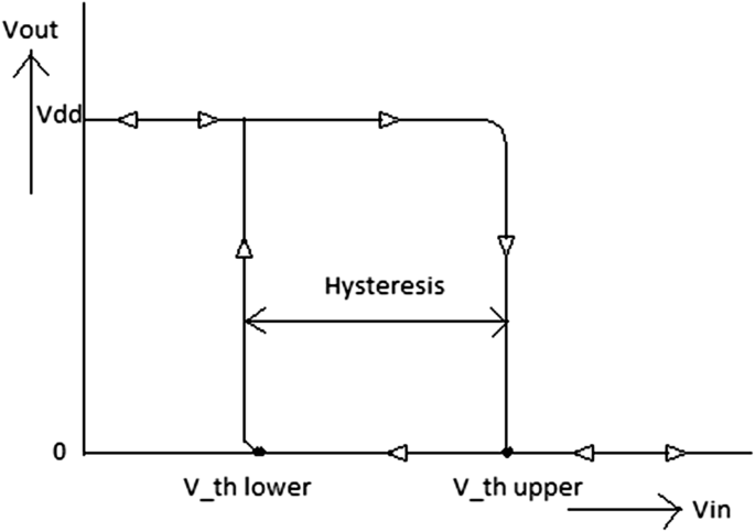
Figure 2: Hysteresis of a Schmitt Trigger
Characteristics of Schmitt Trigger
• Bistable Functionality
Schmitt triggers can maintain one of two possible output states until the input signal crosses a defined threshold. These thresholds, known as the upper (V_U) and lower (V_L) thresholds, determine the conditions under which the output state changes.
• Hysteresis and Positive Feedback
The core of Schmitt triggers' operation is hysteresis, enabled by positive feedback within the circuit. Hysteresis creates a range between V_U and V_L where the output state remains unchanged until the input exceeds the opposite threshold. This design ensures that minor input fluctuations, often caused by electrical noise or transient disturbances, do not cause unwanted changes in the output. This stability prevents rapid state toggling and errors in digital circuits, making Schmitt triggers ideal for timing-sensitive applications.
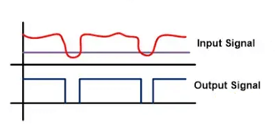
Figure 3: Noise Effect on Input and Output Signal
• Symmetric and Asymmetric Thresholds
Schmitt triggers can be designed with either symmetric or asymmetric threshold levels, offering flexibility for specific applications. Symmetric thresholds are used where equal precision is needed during both the rising and falling edges of a signal. Asymmetric thresholds are useful in scenarios where different behaviors are required based on the direction of the input signal's change, such as in certain pulse conditioners or circuits.
Upper and Lower Trigger Point of Schmitt Trigger
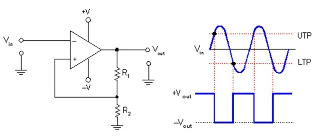
Figure 4: Upper and Lower Trigger Point
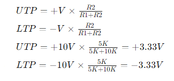
In a Schmitt trigger circuit using an op-amp 741, UTP means the upper trigger point, and LTP means the lower trigger point. If the input surpasses the upper threshold (UTP), the output goes low. And if the input drops below the lower threshold (LTP), the output becomes high. When the input falls between these thresholds, the output remains unchanged.
For example, the hysteresis voltage (V Hysteresis) is calculated as UTP minus LTP.
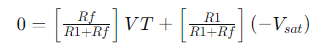
The upper threshold point (UTP) and the lower threshold point (LTP) are where the input signal is compared. So, the values of UTP and LTP are determined by the following formulas:
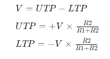
When comparing two levels, oscillation or instability can occur at the threshold. Hysteresis eliminates this issue by preventing such oscillation. Unlike a standard comparator that uses a single reference voltage, a Schmitt trigger utilizes two different reference voltages, known as UTP and LTP.
For the Schmitt trigger circuit using the op-amp 741, the UTP and LTP values can be calculated with the following equations.
How Does a Schmitt Trigger Work?
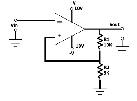
Figure 5: Schmitt Trigger Circuit
A Schmitt trigger uses positive feedback, where part of the output is fed back into the input. This feedback loop is required because it allows the circuit to maintain a stable output state even in the presence of voltage fluctuations or noise. This stable operation prevents erratic outputs in a region known as the 'dead zone,' where input signals could otherwise cause instability.
The Schmitt trigger depends on the interaction between the input voltage, the reference voltage, and the feedback resistor. When the input voltage rises and falls, it crosses specific thresholds that trigger the circuit's response. The lower threshold, when crossed, changes the output state. This state remains until the input reaches the upper threshold, at which point the output flips back to its original state.
This dual-threshold mechanism allows the Schmitt trigger to produce a stable transition between output states, reducing the risk of noise-induced errors. Once an input signal causes a state change, only a significant and opposite input will reverse this state, preventing the output flickering common in traditional comparators. This makes Schmitt triggers highly reliable for applications requiring signal integrity and stability, such as signal conditioning, switch debouncing, and pulse generation circuits.
Enhancing the Schmitt trigger's design involves optimizing the feedback resistor and adjusting the thresholds according to specific operational needs. These improvements ensure the Schmitt trigger meets and exceeds performance expectations in high-stakes applications.
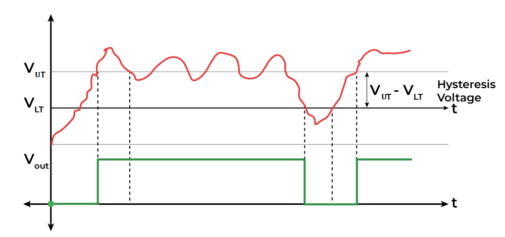
Figure 6: Schmitt Trigger Working
Types of Schmitt Triggers
They come in two main types based on the relationship between their input and output signals: Non-Inverting Schmitt Triggers and Inverting Schmitt Triggers.
Inverting Schmitt Trigger
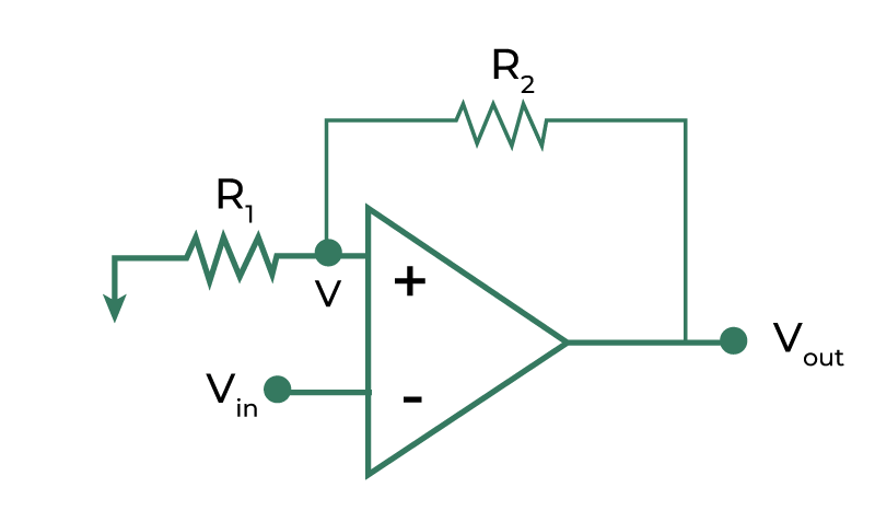
Figure 7: Inverting Schmitt trigger
An inverting Schmitt trigger outputs a signal that is the opposite of the input. When the input signal falls below a specific lower threshold, the output goes high. And, when the input exceeds an upper threshold, the output switches to low. This inversion is achieved through a feedback resistor that creates a hysteresis loop, stabilizing output transitions even with rapidly changing inputs.
Here’s how it works:
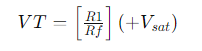
The triggering voltage (VT) is calculated with the formula,
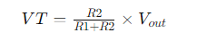
If the output (Vout) is at positive saturation (+Vsat), then VT is positive. If Vout is at negative saturation (-Vsat), then VT is negative.
There are two threshold points:
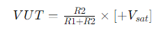
• Upper Threshold (VUT): When output is +Vsat
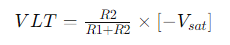
• Lower Threshold (VLT): When output is -Vsat
Here’s how the circuit behaves:
• When the input voltage (Vin) is greater than VT, the output (Vo) goes to -Vsat.
• When Vin is less than VT, Vo goes to +Vsat.
When the input voltage (Vin) is below the upper threshold (VUT), the output remains at positive saturation (+Vsat). As soon as the input voltage exceeds the upper threshold (VUT), the output flips to negative saturation (–Vsat). The output stays in this state until the input voltage drops below the lower threshold (VLT), at which point the output switches back to positive saturation (+Vsat).
So, the output only changes when the input voltage crosses either the upper or lower threshold (VUT and VLT). Between these two thresholds, the output remains stable at either +Vsat or –Vsat, regardless of changes in the input voltage. This range is known as the "dead band" or "hysteresis width" (H).
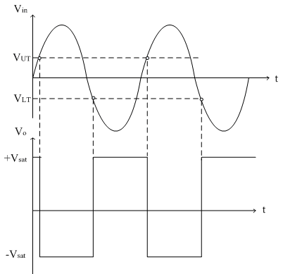
Figure 8: Input and Output Waveforms
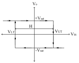
Figure 9: Inverting Schmitt Trigger Form
The transfer characteristics of an inverting Schmitt trigger form a rectangle shape on the graph. This rectangle is called the hysteresis loop. It shows that the output stays the same until the input voltage crosses one of the threshold levels. Moreover, hysteresis loop is also known as the "dead band" or "dead zone" because the output does not change in response to the input signal within this range.
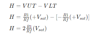
The width of the hysteresis loop (H) is calculated as follows:
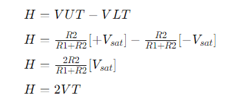
This means the width of the hysteresis loop is twice the triggering voltage (VT).
Applications of Inverting Schmitt Triggers
Inverting Schmitt triggers are widely used in waveform shaping, converting fluctuating analog inputs into stable digital signals. They are good in pulse width modulation (PWM) systems and oscillator circuits, where consistent signal thresholds ensure operational reliability. And their ability to invert signals makes them suitable for circuits requiring reversed logic states, such as certain automated controls and timing circuits.
Advantages of Inverting Schmitt Triggers
The main benefit of inverting Schmitt triggers is their flexibility in handling signals where inverted output is useful. This feature allows designers to create innovative circuit designs, especially in complex digital and timing applications where precise signal processing is require.
Non-Inverting Schmitt Trigger
Non-inverting Schmitt triggers maintain the same polarity between input and output signals. A high output is produced when the input exceeds the upper threshold, and the output switches to low when the input drops below the lower threshold. Similar to inverting triggers, non-inverting triggers use a feedback mechanism to stabilize the output, ensuring reliable performance despite input variations.
Here’s how it works:
The voltage at the non-inverting terminal (V+) is compared with the voltage at the inverting terminal (V-), which is set to (= 0V)
There are two conditions to consider:
• When V+>V- the output voltage Vo=+Vsat
• When
V+<V- the output voltage Vo=-Vsat
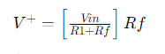
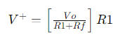
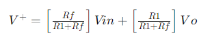
Both the input voltage (Vin) and the output voltage (Vo) influence the voltage at the non-inverting terminal (V+). Using the superposition theorem, we can find V+.
When Vo is grounded:
When Vin is grounded:
The total voltage at V+ is
Triggering points:
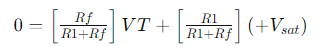
Positive saturation
• When Vo is +Vsat, the output switches to +Vsat when V+ crosses 0V.
• At the switching point, Vin= VT and V+ = 0V.
Using the equation for V+:
Solving for VT:
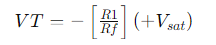
This is the lower threshold point (VLT).
Negative Saturation
• When Vo is -Vsat, the output switches to –Vsat when V+ crosses 0V.
• At the switching point, Vin = VT and V+ = 0V.
Using the equation for V+:
Solving for VT:
This is the upper threshold point (VUT).
The hysteresis width (H) is the difference between the upper and lower threshold points:
This shows the width of the hysteresis loop, indicating the range of input voltage where the output does not change.
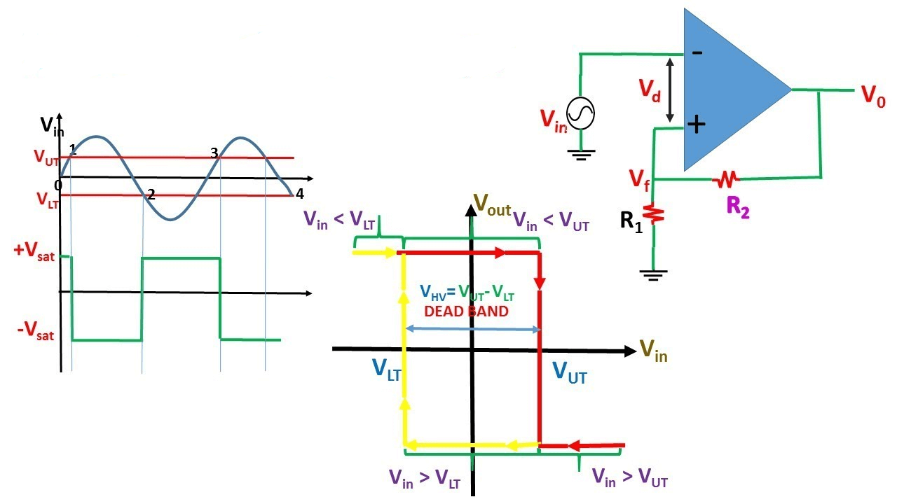
Figure 10: Non-inverting Schmitt Input and Output Waveforms and Schmitt Trigger Form
Applications of Non-Inverting Schmitt Triggers
Non-inverting Schmitt triggers are primarily used in signal conditioning to filter out noise from input signals, making them ideal for applications requiring clean digital outputs from noisy analog inputs. They are also need in generating square waves from sinusoidal inputs and in debouncing circuits for mechanical switches, providing stable and reliable activations.
Advantages of Non-Inverting Schmitt Triggers
The main advantage of non-inverting Schmitt triggers is their straightforward signal processing, aligning output states closely with the input and reducing noise-induced errors. This simplicity, combined with adjustable threshold levels, makes non-inverting triggers suitable for a wide range of electronics, from basic consumer devices to advanced industrial systems.
Schmitt Trigger Using IC 555
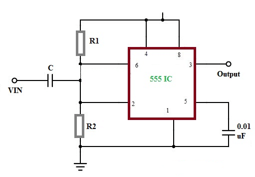
Figure 11: Schmitt Trigger using 555 IC
This circuit can be assembled using basic electronic components with the IC555. Pins 4 and 8 of the IC555 are connected to the Vcc supply, while pins 2 and 6 are shorted together, receiving input through a capacitor.
The common connection point of these two pins can be provided with an external bias voltage using a voltage divider made up of two resistors, R1 and R2. The output maintains its state when the input is between the two threshold values, known as hysteresis, allowing the circuit to function as a memory element.
The thresholds are set at two-thirds Vcc and one-third Vcc. The upper comparator operates at two-thirds Vcc, while the lower comparator operates at one-third Vcc. The input voltage is compared to these thresholds using a separate comparator, subsequently setting or resetting the flip-flop (FF). Depending on the comparison result, the output switches to a high or low state.
Schmitt Trigger Using Transistors
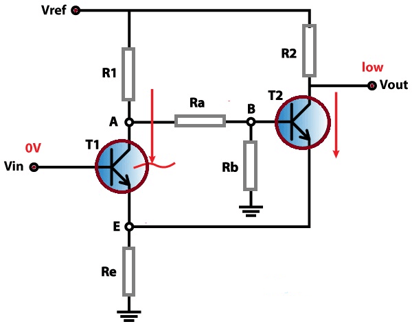
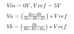
Figure 12: Schmitt Trigger using Transistors
It can be assembled with basic electronic components, with two transistors for this circuit. When the input voltage (Vin) is 0 V, transistor T1 does not conduct, while transistor T2 does, due to the reference voltage (Vref) with the voltage1.98. At node B, the circuit act as a voltage divider, and the voltage can be calculated using the following expressions:
The conducting voltage of transistor T2 is low, with the emitter terminal at 0.7 V, which is less than the base terminal at 1.28 V.
When the input voltage increases, transistor T1 begins to conduct, causing the base terminal voltage of transistor T2 to drop. When transistor T2 stops conducting, the output voltage increases.
As the input voltage at transistor T1's base terminal decreases, T1 deactivates because its base terminal voltage exceeds 0.7 V. This occurs when the emitter current decreases, causing the transistor to enter forward-active mode. As a result, the collector and base terminal voltages of T2 rise, allowing a small current through T2, which further lowers the emitter voltage and turns off T1.
For T1 to deactivate, the input voltage needs to drop to 1.3V. Thus, the two threshold voltages are 1.9V and 1.3V.
Simple Oscillators and Switch Debouncing Using Schmitt Triggers
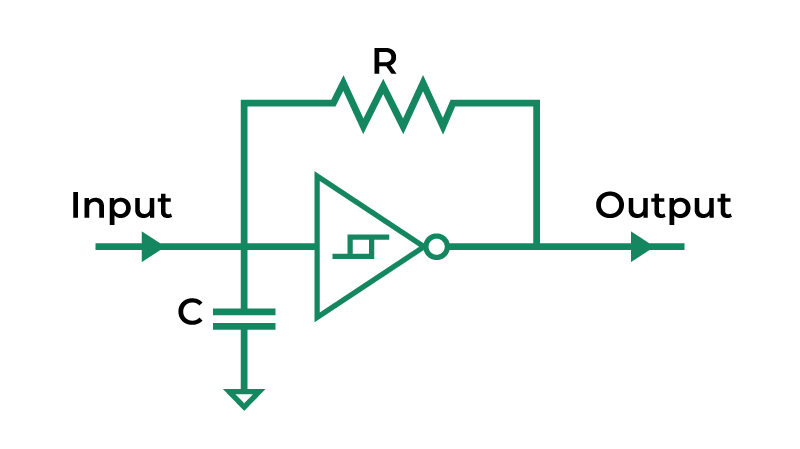
Figure 13: Schmitt Trigger Oscillator
Simple Oscillators
Schmitt triggers can act as simple oscillators, similar to a 555 timer, due to their dual threshold levels. They autonomously generate periodic signals needed for consistent clock pulses or timing references. The oscillation process relies on the predictable charging and discharging of capacitors through these thresholds. This makes Schmitt triggers ideal for various timing and waveform generation tasks in both consumer electronics and industrial systems.
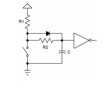
Figure 14: Schmitt Trigger Debouncing
Switch Debouncing
Schmitt triggers are required in debouncing switches. Mechanical switches often produce noisy signals due to their physical characteristics, like elasticity or springiness, leading to multiple, unintended signal transitions. By pairing Schmitt triggers with a resistor-capacitor (RC) circuit, this noise is cleaned up, ensuring each switch press generates a single, clean pulse. This setup improves the reliability and performance of electronic circuits, especially in consumer devices and industrial controls where precise input actions are needed.
Distinctions Between Schmitt Triggers and Comparator
|
ASPECT |
SCHMITT TRIGGERS |
STANDARD COMPARATORS |
|
Fundamental Operation |
Comparator with hysteresis using positive feedback |
Op-amp circuit with two input signals |
|
Output Transitions |
Stable and reliable due to hysteresis |
High or low based on input signal |
|
Response to Input Fluctuations |
Changes at specific input voltage thresholds |
Rapid toggling with minor input fluctuations |
|
Applications |
Converts any waveform into a square waveform |
Zero crossing detector, window detector |
|
Sensitivity Adjustment |
Fine-tuning hysteresis width |
Requires additional external circuitry |
|
Threshold Levels |
Upper (VUT) and Lower (VLT) thresholds |
Defined at 0V or Vref (reference voltage) |
|
Hysteresis |
Present, VH = VUT - VLT |
Not present, hysteresis voltage is zero |
|
External Reference Voltage |
Not required |
Must be applied |
|
Feedback |
Uses positive feedback |
Open loop configuration, no feedback loop |
|
Advantages |
Consistent, noise-resistant outputs |
Simpler, less stable without extra components |
Distinctions Between Schmitt Triggers and Buffers
|
ASPECT |
SCHMITT TRIGGER |
BUFFERS |
|
Fundamental Operation |
Converts analog signals to digital while cleaning up noisy signals. |
Amplifies the input signal to drive larger loads without altering its logic state. |
|
Output Transitions |
Sharp transitions due to hysteresis, which allows for definitive switching. |
Direct, sharp transitions that replicate the input logic state. |
|
Response to Input Fluctuations |
Responsive; stabilizes outputs against brief, irrelevant fluctuations due to hysteresis. |
Less responsive; directly transmits any fluctuations to the output. |
|
Applications |
Used in signal conditioning and ideal in environments with electrical noise |
Used in digital circuits to ensure signal integrity across longer distances or higher load circuits. |
|
Sensitivity Adjustment |
Adjustable via the hysteresis width; can be tuned for different noise levels. |
Typically fixed, based on the buffer design and cannot be adjusted. |
|
Threshold Levels |
Features two threshold levels for switching, which helps in noise immunity. |
One threshold level matching the input logic levels. |
|
Hysteresis |
Yes, contains hysteresis which helps in stabilizing noisy inputs. |
No, lacks hysteresis, making them less effective against noise. |
|
External Reference Voltage |
Can be applied to set the switching thresholds. |
Not applicable; operates based on the input voltage directly. |
|
Feedback |
Positive feedback is good for creating the hysteresis effect. |
No feedback mechanism involved; operates as a simple signal amplifier. |
|
Advantages |
Excellent for noisy environments; reduces signal chatter and false triggering. |
Simple design, low cost, and effective at maintaining signal amplitude without degradation. |
CMOS Schmitt Trigger
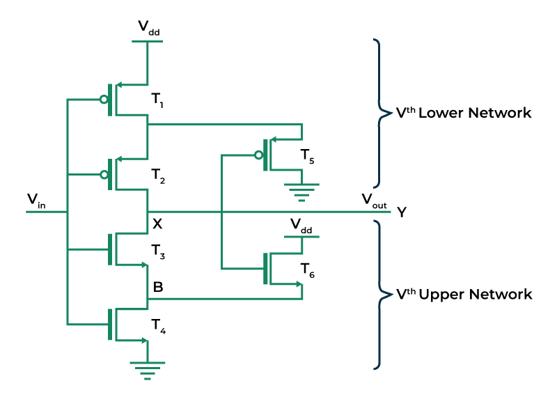
Figure 15: CMOS Schmitt Trigger
CMOS technology significantly improves Schmitt triggers by enabling them to operate at lower power levels. This improvement is required for battery-operated and portable devices where energy efficiency is need. The use of complementary metal-oxide-semiconductor (CMOS) technology in Schmitt triggers takes advantage of CMOS components' low static power consumption.
Integrating CMOS technology allows Schmitt triggers to draw less energy and reduces heat generation during operation, enhancing reliability and durability. This is good for devices needing long operational lifetimes and minimal maintenance. CMOS-based Schmitt triggers also benefit from the technology's scalability and compatibility with other modern semiconductor processes. This makes them widely applicable in digital and mixed-signal environments.
CMOS Schmitt triggers combine traditional threshold logic functionality with advanced low-power semiconductor technology, making them ideal for sophisticated electronic applications. These applications range from embedded systems in automotive and industrial settings to consumer electronics requiring high efficiency and compact design. The strategic use of CMOS technology enhances Schmitt triggers' intrinsic benefits, emphasizing their evolving role in contemporary electronic design.
Schmitt Trigger Impact on Sensors
Schmitt Trigger technology, which reduces noise and produces steady signals, needed in modern electronics because it improves sensor accuracy and reliability. It is used in temperature, sound, and light sensors to filter out unwanted signals and reduce false readings. By setting right thresholds and disregarding small input variations until a large threshold is crossed, this method improves sensor performance while eliminating noise.
Schmitt Triggers manage sensor activation, turning them on or off based on specific conditions, saving power and extending sensor life. They increase a sensor’s measurement range by adjusting thresholds for different signals, enabling accurate measurements in different environments. Setting up Schmitt Triggers involves choosing appropriate thresholds, and once set, they operate automatically, providing consistent and accurate readings without constant adjustment. Schmitt Triggers improve sensor systems, making them accurate and reliable, and beneficial to anyone designing and using sensors in modern electronics.
Advantages and Disadvantages of Schmitt Triggers
Enhanced Performance with Superior Noise Immunity
Schmitt triggers are useful for improving modern electronic circuits because of their excellent noise immunity. They filter out irrelevant signals and noise, ensuring the output remains stable and clear. This reliability is need in precision applications, preventing errors and operational uncertainty caused by noise. Schmitt triggers' ability to maintain consistent output under different conditions helps avoid false triggering.
Versatility in Electronic Systems
Schmitt triggers' versatility makes them widely used across different electronic systems. They are employed in roles ranging from generating precise oscillations in timing circuits to debouncing inputs in mechanical switches. This flexibility makes them a key component in electronic design, adaptable to a wide range of functionalities.
Design Challenges and Calibration Complexity
However, Schmitt triggers also present design challenges. Setting correct thresholds for signal transitions requires precise calibration of the hysteresis curve. Engineers must carefully adjust these thresholds to balance responsiveness with stability, which can complicate circuit design. Achieving optimal performance necessitates meticulous tuning, adding complexity to electronic systems.
Higher Power Consumption
Schmitt triggers typically consume more power than basic comparators due to the additional components needed for hysteresis, such as feedback resistors. This higher power demand can be a drawback in energy-sensitive applications where efficiency is required.
Applications of Schmitt Triggers
Schmitt triggers are widely available in different forms and packages to meet diverse industrial and commercial needs. In the electronic components market, they are often integrated within devices like buffers or inverters. However, not all such devices use Schmitt trigger technology. For instance, the 74HC04 hex inverter includes Schmitt trigger inputs, making it effective in noisy conditions. Similarly, the 4081 quad AND gate features Schmitt trigger inputs, enhancing signal integrity.
Schmitt triggers are available in both DIP (Dual In-line Package) and SMD (Surface Mount Device) forms, catering to different assembly methods and design requirements. Choosing the right package depends on the application’s specific needs, such as space constraints and manufacturing preferences.
Schmitt triggers are suitable for a wide range of projects, from simple DIY electronics to advanced industrial systems. They enhance signal integrity and improve electronic circuit performance, making them need in both hobbyist and professional electronics inventories.
Conclusion
The Schmitt trigger is a prominent part of electronic design, providing precision, reliability, and versatility for a variety of purposes. It helps reduce signal noise and is an essential part of energy-efficient CMOS technology. While designing and calibrating Schmitt Triggers can be complex, their benefits in noise reduction and stability are excellent. They are used in many areas, from sensor signal conditioning to advanced digital circuits, showing their lasting importance and flexibility in evolving technology. Understanding their history, technical aspects, and practical uses highlights the ongoing importance of Schmitt Triggers and their role in future electronic innovations.
Frequently Asked Questions [FAQ]
1. What does a Schmitt trigger do?
A Schmitt trigger is an electronic circuit that functions as a signal voltage level detector and converter. It serves to convert varying input signals into stable digital output signals. The core characteristic of a Schmitt trigger is its hysteresis, a feature that incorporates two different threshold voltage levels: one for transitioning from low to high (the upper threshold) and another for transitioning from high to low (the lower threshold). This dual threshold action helps eliminate noise and provides clean, sharp transitions, which is helpful for stabilizing signals that may be noisy or have fluctuating amplitudes.
2. Why we use Schmitt trigger instead of comparator?
While both Schmitt triggers and comparators are used for comparing voltage levels, Schmitt triggers are preferred in applications requiring greater noise immunity and signal stability. A comparator outputs a high or low state depending on whether the input voltage is above or below a single threshold value. This can lead to rapid toggling of the output if the input signal hovers around the threshold, especially if the signal is noisy. The Schmitt trigger, with its two distinct threshold levels, avoids this problem by providing a clear distinction between the high and low states even in the presence of signal noise, thereby stabilizing the output.
3. Is a Schmitt trigger an inverter?
A Schmitt trigger can be designed to function as an inverter or a non-inverter, depending on the need. In its basic form, a Schmitt trigger outputs a high signal when the input voltage drops below the lower threshold and a low signal when the input exceeds the upper threshold. If designed as an inverting Schmitt trigger, it reverses the input logic, meaning the output is low when the input is below the lower threshold and high when above the upper threshold. Therefore, whether a Schmitt trigger acts as an inverter depends on its specific circuit configuration.
4. Where are Schmitt triggers used?
Schmitt triggers in applications needing clean digital signals from noisy or analog inputs. They are commonly used for signal conditioning to purify sensor outputs before feeding them into digital circuits, square wave generation in oscillators to produce stable signals from noisy or sinusoidal inputs, debouncing switches to ensure a single output transition despite mechanical bounce, and in communication systems to interpret long-distance signals that may have degraded or accumulated noise.
5. What is the value of the Schmitt trigger?
The value of a Schmitt trigger lies in its ability to provide signal stability and noise immunity in digital electronic systems. Its dual-threshold feature helps in converting noisy or analog signals into digital ones without errors induced by signal noise or interference. This capability best in enhancing the reliability and performance of electronic systems, especially in environments subjected to high electromagnetic interference. Thus, Schmitt triggers are indispensable in applications requiring robust digital signal processing.