Quality (Q) Factor: Equations and Applications
The quality factor, or 'Q', is important when checking how well inductors and resonators work in electronic systems that use radio frequencies (RF). 'Q' measures how well a circuit minimizes energy loss and impacts the range of frequencies the system can handle around its main frequency. In systems with inductors, capacitors, and tuned circuits, a higher 'Q' means the circuit focuses more on a specific frequency, making it more precise.This article looks at the role of the Q factor in different areas, like RF circuits, mechanical systems, and optical technologies, showing how it affects bandwidth, signal stability, and energy efficiency. It explains how the Q factor influences things like bandwidth control, frequency accuracy, reducing noise, keeping oscillations stable, and reducing unwanted movement. The article also discusses how the Q factor is calculated in different systems.
Catalog
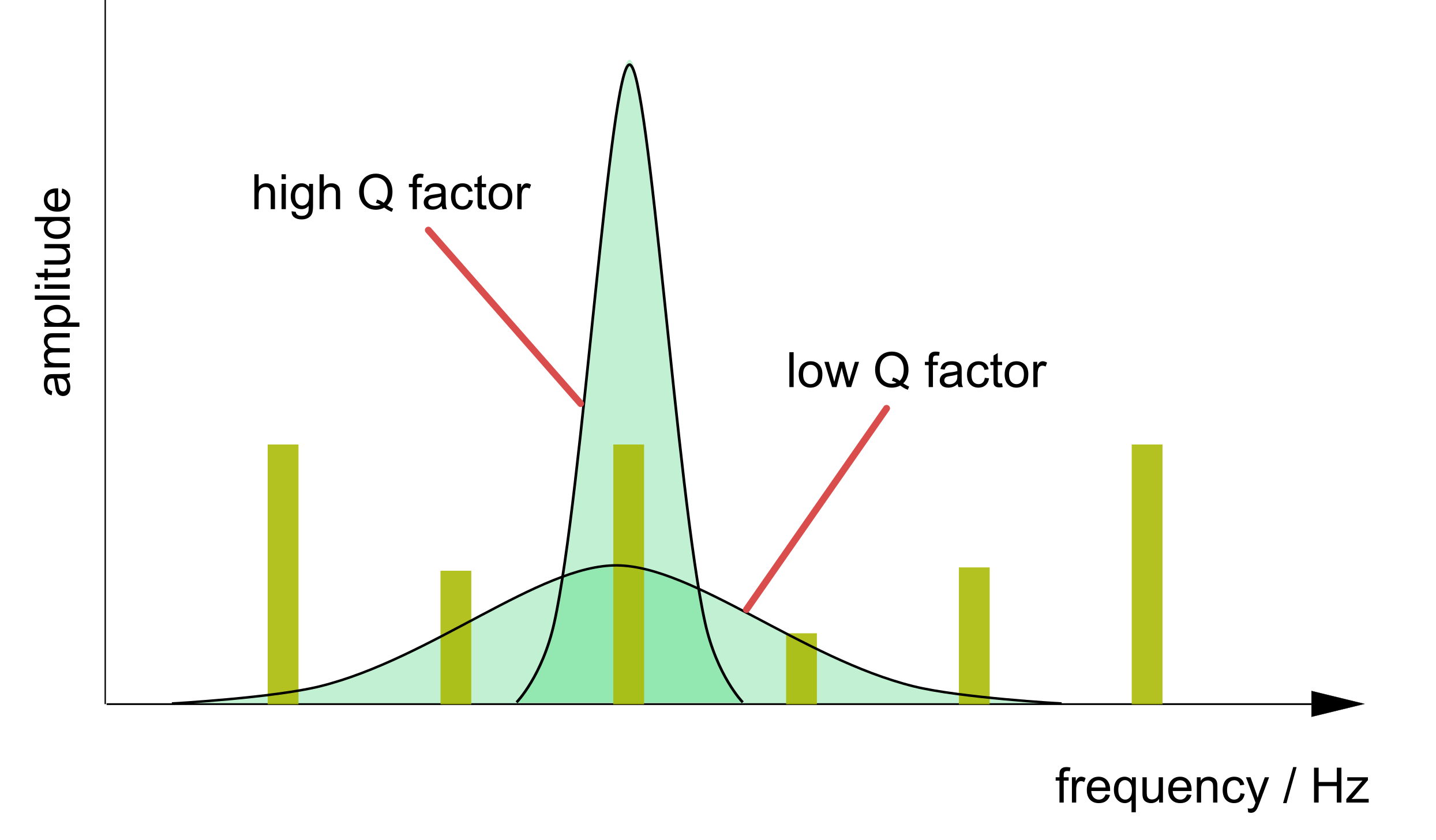
Figure 1: The Q Factor
Origins of the Quality Factor
The concept of the quality factor, or 'Q', was first introduced by K. S. Johnson from Western Electric Company’s Engineering Department in the early 20th century. Johnson was researching the efficiency of coils in transmitting and receiving signals and he need a way to measure their performance more precisely. To address this, he developed the 'Q' factor as a numerical tool for evaluating how effectively coils performed in these applications.
The choice of the letter 'Q' wasn’t based on any specific technical reasoning. Johnson simply selected it because most other letters had already been assigned to different parameters. This accidental choice turned out to be quite fitting, as 'Q' would soon become associated with quality in electronic circuits. The 'Q' factor provided a clear standard for improving performance in various electronic components, making it great concept in the field.
Impact of the Q Factor on RF Design
Bandwidth and Frequency Selectivity
In radio frequency (RF) design, role of the Q factor is how it affects bandwidth. A high Q factor creates a narrow bandwidth that is important when we need to focus on specific frequencies. For example, in filters or tuned amplifiers, a narrow bandwidth helps the system to lock onto a certain frequency and block unwanted signals, reducing interference. This precision is good for systems like cell networks, satellite communications, or radar, where signals must be sent and received at precise frequencies with minimal error.
Sometimes, a lower Q factor with a wider bandwidth is better. Systems like Wi-Fi or TV broadcasting, deal with multiple frequencies or complex signals, benefit from this. A lower Q factor helps the system handle more frequencies and work more flexibly, which is important in broadband communication where flexibility matters more than precise frequency control.
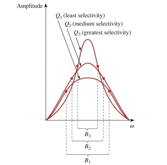
Figure 2: The Q Factor Bandwidth and Frequency
Reducing Phase Noise and Unwanted Signals
The Q factor also affects phase noise in RF systems. Phase noise refers to small changes in the signal's phase, can mess up signal quality and cause problems like jitter or unwanted signals. A high-Q oscillator can reduce phase noise, creating a clearer and more stable signal. This is very important in systems like GPS, frequency synthesizers, or high-speed data communication, where even small errors in the signal can cause big problems. By reducing phase noise, a high Q factor makes the signal more reliable.
In addition, high-Q circuits are better at rejecting unwanted frequencies, making sure only the desired signal is transmitted. This is useful in fields like medical imaging or military radar, where having a clean, accurate signal is extremely important.
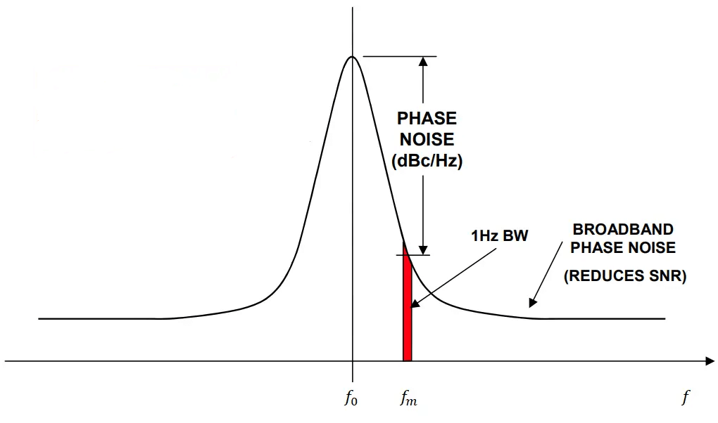
Figure 3: A Phase Noise Measurement
Oscillation and Stability
The Q factor also affects how well a circuit can maintain oscillations (repeated signals) in resonant circuits. A high Q factor helps the circuit keep oscillations going with minimal energy loss, useful in systems that need stable signals over time, like RF clock generators. High-Q circuits have less signal damping, meaning the oscillations last longer, leading to more stable performance.
However, in systems that need to respond quickly or work across a wide frequency range, too much oscillation can be a problem. In these cases, a lower Q factor helps the circuit react faster and avoid excessive ringing, improve performance in dynamic systems like adaptive communication networks.
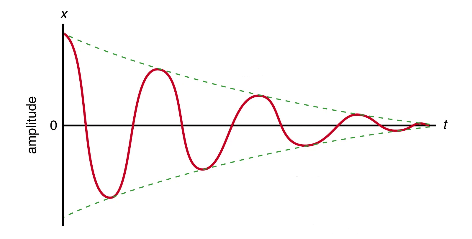
Figure 4: Oscillator and Q Factor
Quality Factor’s Influence on Damping
The Quality Factor (Q factor) measures the degree of damping in a system, directly affects the oscillations and how quickly the system stabilizes after a disturbance.
When a circuit is disturbed, such as by a step impulse, its behavior can fall into one of three categories depending on the Q factor: under-damping, over-damping, or critical damping.
In systems with a high Q factor, under-damping happens. This causes the system to keep oscillating for a longer time, as it loses only a little energy with each cycle. The oscillations slowly get smaller, so while the system stays active for longer, it also takes more time to settle down. Under-damped systems are useful when you want continuous oscillations, like in radio frequency (RF) circuits or filters.
If the Q factor is low, over-damping occurs. In this case, the oscillations stop quickly, and the system returns to normal without bouncing back and forth. Over-damped systems take longer to react but are more stable, helpful in systems that need to calm down without any extra fluctuations, like control systems or power electronics.
Critical damping happens when the system settles down as fast as possible without oscillating at all. It’s the perfect middle ground between being quick and stable, making it ideal for things like car suspension or some electronics, where you want a fast, smooth response without any extra movement.
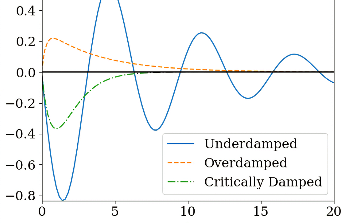
Figure 5: Under-Damping, Over-Damping, and Critical Damping
Mathematical Representation of the Q Factor
In Electrical Circuits (Resonance Circuits)
For a resonant RLC circuit (which includes a Resistor, Inductor, and Capacitor), the Q factor can be represented as:
![]()
This can also be written as:

Where:
R = Resistance (measures energy loss)
L = Inductance (measures how much magnetic energy is stored)
C = Capacitance (measures how much electric energy is stored)
Here, a high Q factor means the circuit resonates strongly and loses energy slowly, while a low Q factor means it loses energy quickly.
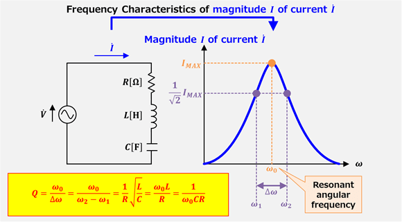
Figure 6: Q Factor of RLC Series Resonant Circuit
In Mechanical Systems (Oscillators)
For mechanical systems, like a pendulum or a mass-spring system, the Q factor is a measure of how "damped" or "undamped" the oscillations are.
The formula is:
![]()
This can also be written as:
![]()
Where:
![]() = Resonant frequency (the frequency where the system oscillates the most)
= Resonant frequency (the frequency where the system oscillates the most)
![]() = Bandwidth (the range of frequencies over which the system resonates)
= Bandwidth (the range of frequencies over which the system resonates)
A high Q factor means less energy loss and sharper resonance, while a low Q factor indicates faster energy loss and broader resonance.
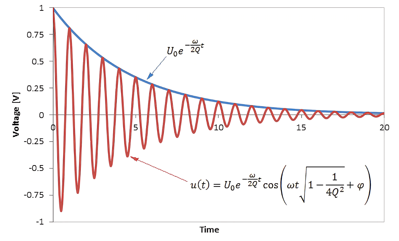
Figure 7: Measuring Q Factor for Mechanical Systems
In Optics (Cavities and Lasers)
In optical systems, the Q factor describes the sharpness of resonance in optical cavities, such as those used in lasers. It can be calculated similarly:
![]()
In optics, this high Q means that the light bounces many times before losing energy, creating a sharp, well-defined frequency for the laser or optical cavity.
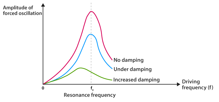
Figure 8: Q Factor and the Sharpness of Resonance
In Filters (Electronic or Acoustic)
The Q factor in filters describes the selectivity or sharpness of the filter's passband or resonance.
The formula is:
![]()
Where:
• Center Frequency is the frequency at which the filter is most selective.
• Bandwidth is the range of frequencies the filter allows through.
A high Q factor in filters means that only a narrow range of frequencies passes through (more selective), while a low Q allows a wider range (less selective).
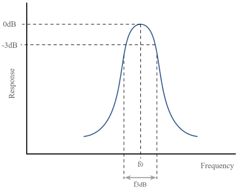
Figure 9: Q Factor In Filters
How to Calculate Capacitance and Q Factor?
You are tasked with designing a tuning circuit for a radio receiver that requires sharp selectivity, meaning it must effectively distinguish between radio stations that are close in frequency.
The circuit should resonate at 1 MHz, and it has an inductance of 10 microhenries (10 µH) and a resistance of 5 ohms.
Your objective is to determine the capacitance for the circuit to achieve this resonant frequency and calculate the quality factor (Q) to ensure the circuit meets the required selectivity specifications.
First, calculate the resonant frequency.
The resonant frequency of an RLC circuit is described by the formula:
![]()
We can rearrange the equation to solve for capacitance C:
![]()
Second, calculate the capacitance.
Substitute the given values into the formula.
• f0 = 1MHz = 1 × 10⁶Hz
• L = 10μH = 10 × 10−6H
![]()
Using a calculator to simplify:
![]()
This means the required capacitance is about 2.533 picofarads.
Third, calculate the quality factor (Q).
The quality factor Q is a measure of the circuit's selectivity and is calculated using the formula:

Substitute the known values:
![]()
![]()
![]()
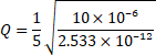
Calculating this yields:
![]()
So, to achieve the desired resonance at 1 MHz, a capacitance of about 2.533 pF is required. The quality factor of the circuit is approximately 280. This high Q value indicates that the circuit is highly selective, means it can effectively tune into a specific radio station while rejecting nearby stations that are close in frequency. This makes the circuit well-suited for radio tuning applications.
The Q Factor in a Lightly Damped Mass-Spring System
Imagine a basic mass-spring system set up in a physics lab. In this setup, a mass (m) is connected to a spring with a specific spring constant (k). The mass can move back and forth along a frictionless surface after being displaced from its resting position.
The system consists of a mass (m) of 0.5 kg, connected to a spring with a spring constant (k) of 200 N/m. The damping coefficient (b) for the system is 0.1 Ns/m, indicating a slight resistance to motion. The mass is displaced by 0.1 m from its equilibrium position, setting up the initial conditions for its motion.
Oscillation Characteristics
Natural Frequency (ω₀): The natural frequency, or the frequency at which the system oscillates without any damping, can be determined using the formula:

where k is the spring constant and m is the mass.
Damping Ratio (ζ): The damping ratio tells us how much the system resists oscillation. It’s calculated by the equation:
![]()
where b is the damping coefficient.
Damped Frequency (ωₑ): If the system experiences damping, the oscillation frequency is slightly lower than the natural frequency. The damped frequency is calculated by:
![]()
Resonant Frequency and Bandwidth Calculations
Resonant Frequency (![]() ): This is the frequency at which the system would oscillate in the absence of damping. It is related to the natural frequency, ω₀, by:
): This is the frequency at which the system would oscillate in the absence of damping. It is related to the natural frequency, ω₀, by:
![]()
Bandwidth (![]() ): The bandwidth measures how spread out the frequency range is around the resonant frequency, where the system still oscillates with at least half the peak power. An approximation for bandwidth is:
): The bandwidth measures how spread out the frequency range is around the resonant frequency, where the system still oscillates with at least half the peak power. An approximation for bandwidth is:
![]()
where Q is the quality factor of the system.
Energy Dynamics
Energy Stored in the Spring: The potential energy stored in the spring when the mass is at its maximum displacement (A) is given by:
![]()
Energy Lost per Cycle: Energy loss happens due to the damping force. For systems with light damping, the energy lost in one cycle can be approximated as:
![]()
Quality Factor (Q) Calculation
The quality factor, ![]() , indicates how underdamped the system is, with higher values meaning less energy loss. It can be found using:
, indicates how underdamped the system is, with higher values meaning less energy loss. It can be found using:
![]()
Applying the Formulas with the Given Values
Using the parameters for the spring constant ![]() and displacement
and displacement ![]() :
:
![]()
The natural frequency is:
![]()
The resonant frequency is then:
![]()
For the damping coefficient b=0.1 Ns/m :
![]()
With the damping ratio, the damped frequency becomes:
![]()
The energy lost per cycle is:
![]()
Substituting the values for energy stored and energy lost:
![]()
So, in this mass-spring system, the quality factor of approximately 500.76 shows that the system is only lightly damped, losing a small amount of energy per cycle. It has a sharp resonance around 3.183 Hz, making it well-suited for experiments where observing long-lasting oscillations or resonance is important, such as in studies of resonance phenomena and damping effects.
Calculating the Q Factor of a Band-Pass Filter in Audio Systems
We're designing an audio filter for a stereo system that emphasizes a specific frequency range around 1000 Hz. This kind of filter is useful when we want to bring out certain instrumental sounds in a music track that might otherwise get lost among other frequencies.
Center Frequency (![]() ): 1000 Hz (the frequency we want to highlight)
): 1000 Hz (the frequency we want to highlight)
Bandwidth (![]() ): 50 Hz (the range of frequencies allowed around the center frequency, from 975 Hz to 1025 Hz)
): 50 Hz (the range of frequencies allowed around the center frequency, from 975 Hz to 1025 Hz)
To determine the filter's sharpness or selectivity, we calculate its Q factor. The formula for Q factor is:
![]()
Now, using our parameters:
![]()
![]()
Plugging these into the equation:
![]()
A Q factor of 20 means the filter is highly selective. It only allows a narrow band of frequencies near the center (1000 Hz) to pass through. This is ideal for audio situations where you want to make a particular instrument stand out, while minimizing interference from frequencies outside that band.
If the Q factor were lower, the filter would allow a wider range of frequencies to pass, making it less selective. In that case, the specific sound you’re trying to highlight could blend in with other nearby frequencies, reducing the clarity of the effect.
Conclusion
The study of the Q factor across different systems shows how important it is in affecting the performance of electronic, mechanical, and optical devices. It helps improve things like sharp tuning in radio frequencies and makes signals clearer and more stable in GPS and telecommunications. Looking closely at how it impacts damping, oscillations, and energy use gives useful ideas for building better systems. As technology moves forward, knowing how to control the Q factor will continue to be important for advancing things like satellite communication, medical tools, and everyday electronics, helping these systems meet modern needs and push the limits of what is possible.
Frequently Asked Questions [FAQ]
1. What is Q factor used to measure?
The Q factor, or quality factor, measures how effectively a resonator, like an electrical circuit or mechanical system, stores energy relative to the energy it loses per cycle. It is primarily used in contexts involving oscillators and resonant circuits where it indicates the damping of the system. A higher Q factor signifies less energy loss relative to the stored energy, indicating a sharper resonance peak in the frequency response.
2. What is the Q value function?
The function of the Q value is to provide a metric for assessing the sharpness of the resonance peak of a system. It quantifies the selectivity and stability of a resonator, such as in filters, oscillators, and cavities. A high Q value means the device can select or reject frequencies very close to its resonant frequency, especially in applications like radio frequency (RF) filters and oscillators.
3. What is a good Q factor?
A "good" Q factor is context-dependent, varying by application. For applications requiring high selectivity, such as in bandpass filters or narrowband antennas, a high Q factor (e.g., hundreds or thousands) is desirable. In contrast, for broadband applications, a lower Q factor, which results in a wider bandwidth and faster response, is typically more advantageous.
4. What is radiation quality factor Q?
Radiation quality factor Q, particularly in the context of antennas, measures the efficiency of an antenna in radiating the energy it receives. It compares the stored energy in the near-field around the antenna to the energy radiated to the far-field. A lower radiation Q indicates more efficient radiation and a wider bandwidth, beneficial for transmitting a broader range of frequencies.
5. What is the quality factor in AC?
In AC circuits, the quality factor describes how underdamped an oscillator or circuit is. It's calculated as the ratio of the reactance of the inductive or capacitive elements to the resistance within the circuit. A higher Q in AC circuits indicates a sharper resonance peak, which means the circuit is more selective to a narrow range of frequencies around its natural frequency.
6. What is the advantage of Q factor?
The advantages of a high Q factor include improved selectivity in frequency discrimination, greater stability in frequency control, and higher efficiency in energy conservation during oscillations. This makes high-Q components ideal for filters, oscillators, and resonant circuits where precise frequency control and minimal energy loss are important. For broader frequency applications, a lower Q may be more beneficial, as it allows for a wider operational bandwidth and quicker transient response.