Push Button Switches
Push button switches are common yet important parts of many electronic and mechanical systems. Whether you’re turning on a light, controlling machines, or using everyday devices, these switches provide a simple and effective way to manage electrical circuits. Their versatility and reliability make them widely used in both home gadgets and industrial machines. In this article, we will explore the basics of push button switches, look at their different types and specifications, and discuss what to consider when choosing the right switch for your needs.Catalog

Figure 1: Push Button Switch
Understanding Push Button Switches
What Is a Push Button Switch?
A push button switch is a mechanical device used to control an electrical circuit. When you press the button, it activates an internal mechanism that either allows or stops the flow of electricity. These switches are basic parts in many electronic devices and systems.
Push button switches come in many shapes, sizes, and designs to fit different needs. For example, they can be momentary or latching. A momentary push button switch only works while you are pressing it. Once you let go, it goes back to its original position. This type is often found in keyboards or doorbells. On the other hand, a latching push button switch stays in its new position after being pressed. You need to press it again to return it to its original position. Light switches often use this latching type.
Inside a push button switch, there are a few main parts: the button, the casing, the moving part, and the contacts. When you press the button, the moving part shifts, causing the contacts to either touch (closing the circuit) or move apart (opening the circuit). This simple system ensures the switch works reliably to control the electrical signals.
Push button switches are designed to handle different electrical loads and work in various conditions. They can vary in terms of how much voltage and current they can handle, as well as their resistance to things like dust, moisture, and temperature. This makes them suitable for a wide range of uses, from consumer electronics to industrial machinery.
How Does a Push Button Switch Operate?
A push button switch works in a simple way by either connecting or disconnecting an electrical circuit. When you press the button, it changes the state of the circuit. This switch can be used as an input for user interfaces or to start and stop devices.
There are two main types of push button switches: momentary and maintained.

Figure 2: Momentary Switch
Momentary switches only work while you are pressing the button. Once you release the button, it goes back to its original state, and the circuit either connects or disconnects for a short time. These switches are used in devices where a short-term input is needed, like a keyboard or a doorbell.
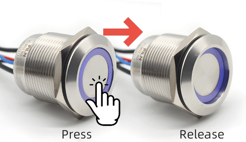
Figure 3: Maintained Switch
Maintained switches stay in their new state after you press the button. When you push the button, the circuit stays either open or closed until you press the button again to change it back. These switches are often used in light switches or power buttons on electronic devices, where the circuit needs to stay changed until you manually change it again.
Inside a push button switch, there is usually a spring that makes sure the button goes back to its original position in momentary switches. In maintained switches, there is a latching mechanism that keeps the button in its new position until you press it again. These internal parts make sure the switch works reliably, giving either a short-term or long-term change in the circuit based on the type of switch used.
Types of Push Button Switches
Push button switches are basic components in many electronic and mechanical systems. They work as simple control devices, allowing users to operate a system by pressing a button. These switches come in two main types: normally open (NO) and normally closed (NC). Understanding the differences between these two types helps in designing and fixing circuits.
Normally Open (NO) Push Button Switch

Figure 4: Normally Open (NO) Push Button Switch Diagram
A normally open (NO) push button switch completes an electrical circuit only when the button is pressed. In its usual state, the inside parts of the switch are separated, preventing electricity from flowing through the circuit. When the button is pressed, these parts come together, allowing electricity to pass and turning on the connected device. This type of switch is often used in situations where the device should be off by default, such as doorbells or keyboard keys. When the button is released, the parts go back to their separated position, stopping the flow of electricity and turning off the device.
On the other hand, a normally closed (NC) push button switch interrupts the circuit when the button is pressed. In its usual state, the inside parts of the switch are connected, allowing electricity to flow through the circuit. Pressing the button causes these parts to separate, stopping the flow of electricity and turning off the connected device. This type of switch is usually used in safety or emergency stop systems, where it is necessary for the device to stay on until someone presses the button to stop it. When the button is released, the parts connect again, allowing electricity to flow and the device to work normally again.
Normally Closed (NC) Push Button Switch

Figure 5: Normally Closed (NC) Push Button Switch Diagram
A normally closed (NC) push button switch is designed to break an electrical circuit when the button is pressed. In its usual state, the internal contacts of the switch are connected, allowing electrical current to pass through the circuit. When the button is pressed, these contacts are physically separated, stopping the current flow and turning off the connected device. This action ensures that the device stops working.
The NC push button switch is often used in safety or emergency stop systems. In these situations, it is very important that the circuit stays active under normal conditions to keep the system running. The switch only needs to be pressed to stop the system in case of an emergency or when it is necessary to stop operations. This design makes sure that the system will continue to work until someone presses the button, which then quickly cuts the power and stops the operation.
In simpler terms, when the NC push button is in its usual, unpressed state, the switch contacts are closed, creating a closed circuit. Current flows without interruption from the power source, through the switch, and to the device. When the button is pressed, the contacts open, creating an open circuit. This stops the current from reaching the device, turning it off. The quick and reliable action of this switch makes it very useful for safety applications, where stopping operations immediately is sometimes necessary to prevent accidents or damage.
Both types of switches are useful in different situations, and choosing the right type depends on what you want the circuit to do. For example, in a safety system, an NC switch might be better to ensure that machinery stops immediately when the button is pressed. In a signaling system like a doorbell, an NO switch would be more suitable since the circuit should only be completed when the button is pressed.
Further classification of switches is based on their switching circuits, which determines how they connect and control electrical circuits:
Single Pole, Single Throw (SPST) Switches
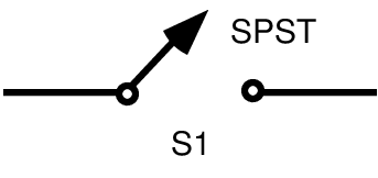
Figure 6: Single Pole, Single Throw (SPST) Switch Diagram
A Single Pole, Single Throw (SPST) switch is the simplest kind of electrical switch, having only two terminals. Its main job is to either open or close one electrical circuit, much like a basic on/off switch in your home. Think about how a light switch works: when you flip it up, it completes the circuit and turns the light on. When you flip it down, it breaks the circuit and turns the light off.
To make this clearer, let's look at a home light switch. When you push the switch up, it closes the circuit. This lets electricity flow through, lighting up the bulb. When you push the switch down, it opens the circuit. This stops the electricity from flowing and the light goes out.
People use this type of switch a lot because it is simple and works well. It is often used in situations where you only need a basic on/off control. The straightforward design of the SPST switch makes it easy to install and operate, providing a reliable way to control electrical circuits.
Single Pole, Double Throw (SPDT) Switches
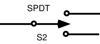
Figure 7: Single Pole, Double Throw (SPDT) Switch Diagram
A Single Pole, Double Throw (SPDT) switch is an electrical part with three connection points. This type of switch can direct the flow of electricity to one of two different circuits. Think of it like a railway switch that can guide a train onto one of two different tracks.
The SPDT switch has one main connection point (C) and two output points (A and B). When the switch is in one position, it connects the main point to point A, allowing electricity to flow through the first circuit. When you flip the switch to the other position, it connects the main point to point B, directing electricity to the second circuit.
Let's consider a fan with an SPDT switch that controls its speed. When the switch connects the main point to the high-speed circuit, the fan runs fast. When you flip the switch to the low-speed circuit, the fan runs slowly.
SPDT switches are very useful in many situations, such as choosing between power sources, switching audio inputs, or controlling different modes in electronic devices. Their ability to switch between two circuits with a simple toggle makes them very handy in both simple and complex electrical systems.
Double Pole, Single Throw (DPST) Switches
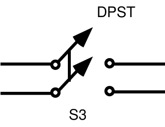
Figure 8: Double Pole, Single Throw (DPST) Switch Diagram
A Double Pole, Single Throw (DPST) Switch is a type of electrical switch that allows you to control two separate circuits at the same time with one action. This means that when you flip the switch, you either open (disconnect) or close (connect) both circuits together. The term "double pole" means the switch can manage two separate circuits, while "single throw" means the switch has only one position for on (closed) and one position for off (open).
To understand how a DPST switch works, imagine you have two electrical devices, like a light and a fan, that you want to turn on or off at the same time. By using a DPST switch, you can make sure both the light and the fan are either turned on or off together. This happens because the DPST switch has four connection points: two input points and two output points. When the switch is in the "on" position, it connects the input points to the output points for both circuits, letting electricity flow through both devices. When the switch is in the "off" position, it disconnects them, stopping the electricity and turning off both devices.
The benefit of a DPST switch is that it can control two separate circuits with one switch. This is especially useful in situations where you need to control multiple circuits at once, making things simpler and making sure both circuits are always in the same state (either both on or both off). DPST switches are often used in places where safety and efficiency are very important, like in industrial control panels and home automation systems. Using a DPST switch can simplify your setup and make your electrical system more reliable.
Double Pole, Double Throw (DPDT) Switches
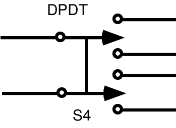
Figure 9: Double Pole, Double Throw (DPDT) Switch Diagram
Double Pole, Double Throw (DPDT) switches are very useful components in electrical circuits. They have six terminals and can control two separate circuits at the same time. This type of switch works like two Single Pole, Double Throw (SPDT) switches combined into one. This allows it to direct current through different pathways within a device.
When using a DPDT switch, you can change the flow of electricity to make different things happen. For example, in an electric motor, a DPDT switch can make the motor spin in the opposite direction by changing the path of the current. This is done by switching the connections at the terminals, which reverses the direction of the voltage applied to the motor.
DPDT switches are very flexible because they can change circuit paths and functions easily. By reconfiguring the connections, you can control different operations within a complex device. This allows precise and adaptable control over the electrical system, making DPDT switches very valuable in situations that need detailed control and flexibility in circuit design.
Key Push Button Switch Specifications
Comparing push button switch models through datasheets is very useful. Current and voltage ratings make sure they match the design needs. Common ways to attach them include surface mount, through hole, and panel mount. Main specifications to consider are:
|
Specification |
Typical
Offering |
Description |
|
Termination Style |
Gull wing, PC pin, wire lead, screw terminal |
Different mounting options |
|
Voltage Rating |
Up to 24 Vdc |
Maximum voltage across the device |
|
Current Rating |
Up to 14 mA |
Maximum current through the device |
|
Actuator Height |
Flush, 3.3 mm, 5.4 mm, and beyond |
Considerations for vertical space and
accidental activation |
|
Pitch |
2.54 mm or 5.08 mm |
Distance between pin centers |
|
Actuator Cap |
Various colors/finishes |
Based on application needs or user
preference |
|
IP Rating |
Rated or non-rated |
Resistance to moisture and dust |
For maintained switches, an LED light can help users quickly see if the switch is on, although it’s not needed for momentary switches. The materials used in switches can be chosen to make them last longer depending on how they will be used.
Push Button Switch Applications and Considerations

Figure 10: Push Button Switch Applications and Considerations Display
Push button switches, integral to classic arcade machines, have expanded their utility across various sectors. In consumer electronics, they are ubiquitous in devices such as remote controls, calculators, and coffee makers. Within the automotive industry, they are employed for tasks like starting engines and operating windows. Additionally, these switches are prominent in vending machines, portable equipment, household appliances, and power tools, underscoring their versatility in both consumer electronics and industrial controls.
When selecting a push button switch, several technical factors must be considered to ensure optimal performance in the intended application. The actuation method, which can be momentary or maintained, determines whether the switch returns to its original position after being pressed or stays in the new position until pressed again. Mounting style is another critical factor, with options including panel mount, surface mount, and through-hole, each offering different advantages based on the design requirements.
Current and voltage ratings help ensure the switch can handle the electrical load without failure. Exceeding these ratings can lead to overheating or electrical shorts, compromising safety and functionality. Additionally, features such as LED indicators can provide visual feedback, enhancing usability, while robust materials can offer increased durability, making the switch suitable for harsh environments or high-frequency use.
A thorough understanding of these aspects—actuation method, mounting style, current and voltage ratings, and additional features—facilitates the selection of the appropriate push button switch for specific applications, ensuring reliability and efficiency in operation.
Conclusion
Push button switches play a major role in many applications, from home electronics to industrial machines. Whether you need a switch that stays on only while pressed or one that stays on until pressed again, a normally open or normally closed type, or a specific voltage and current rating, careful consideration of these factors ensures the switch works well and lasts long. As technology continues to improve, push button switches will remain a basic part of the smooth operation of electronic and mechanical systems, showing their ongoing value in modern engineering and design.
Frequently Asked Questions [FAQ]
1. What are the advantages of push button switches?
The advantages of push button switches include their ease of use, reliability, and quick operation. They are easy to install and can handle different electrical loads, making them useful for many applications.
2. What are the disadvantages of push buttons?
The disadvantages of push buttons are that they can wear out over time with repeated use, may not handle high-current applications well without extra components, and can sometimes be accidentally pressed, causing unintended actions.
3. Why are push buttons used?
Push buttons are used because they offer a simple and effective way to control electronic devices. They let users easily interact with and operate devices by pressing the button to perform a specific task.
4. What is the difference between a push button and a press button?
There is no difference between a push button and a press button. Both terms refer to the same type of device that controls an electrical circuit by being pressed. They are used interchangeably to describe a button that you press to open or close a circuit, turning a device or a function within a device on or off.
5. What is the action of a push button?
The action of a push button is to either connect or disconnect an electrical circuit when pressed. When you press the button, it changes the state of the circuit, either allowing electricity to flow (turning the device on) or stopping the flow of electricity (turning the device off). The button typically returns to its original position when released, unless it is designed to stay in the pressed position until pressed again.