Op Amp Slew Rate: Working & Its Applications
The slew rate of an operational amplifier (op amp) is how quickly the output voltage can change in response to a fast-changing input signal. It's important because it allows the op amp to handle fast signals without distortion, keeping the signals clear and accurate in various electronic applications. This rate, measured in volts per microsecond (V/µs), where there are high-frequency signals or quick changes in the input.This article takes a detailed look at how different design choices in amplifiers, like frequency compensation, output stage setup, and internal capacitance, affect how op-amps work. It also talks about the balance between slew rate and bandwidth, and compares different amplifiers to help with choosing the right one for specific uses.
Catalog
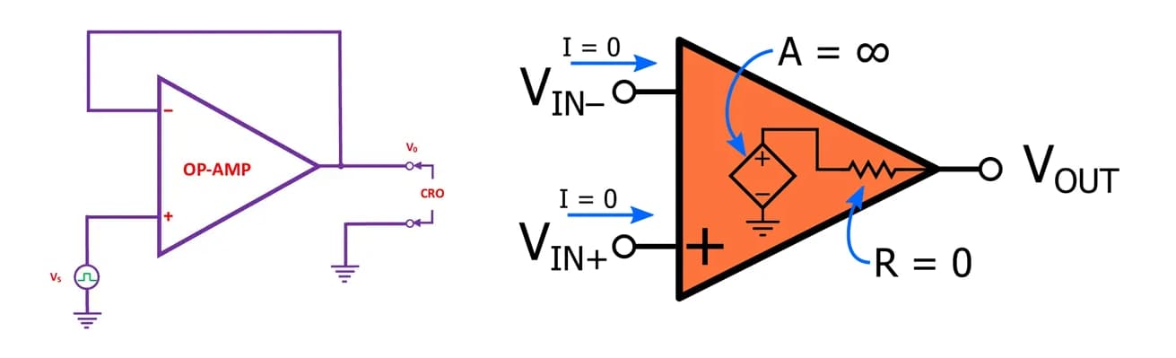
Figure 1: Slew Rate Measurement Circuit
Factors Influencing Slew Rate in Operational Amplifiers
Several elements affect this rate, influencing the overall performance of the op-amp.
Frequency compensation is important to keep an op-amp stable under various conditions. It involves using internal parts like compensation capacitors and feedback loops to avoid problems like oscillations at high frequencies. However, these parts also slow down how quickly the op-amp can respond to fast changes in the input signal, limiting the slew rate. So, while they help with stability, they also reduce the op-amp's speed in reacting to sudden changes.
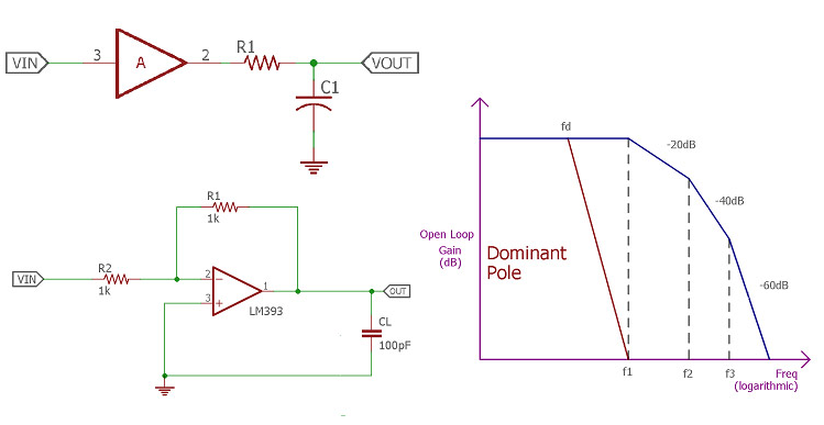
Figure 2: Frequency Compensation of Op-Amp
The design of the output stage in an op-amp is another main factor that impacts the slew rate. This stage includes components like output transistors and circuits that provide the current need to drive the load. The size and design of these parts determine how much current can be supplied to charge or discharge any connected capacitors that directly affects the slew rate. For example, bigger transistors can provide more current, allowing the output voltage to change more quickly. Similarly, circuits that boost current can help the op-amp respond faster to sudden input changes, improving the slew rate.
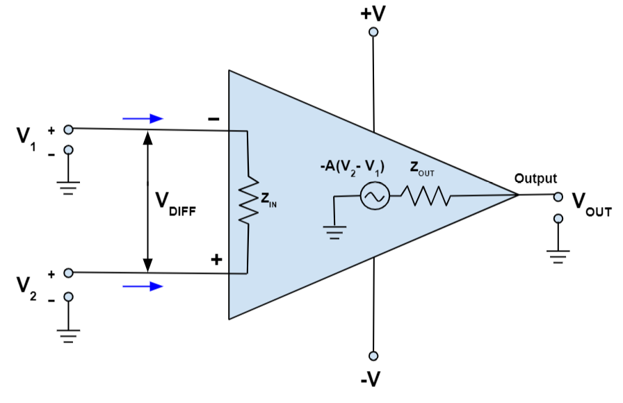
Figure 3: Op-Amp Output Stage Design
Inside an op-amp, different capacitors store and release charge as the device operates. The total amount of internal capacitance in feedback and compensation networks, influences the slew rate. This capacitance controls how quickly the op-amp can charge and discharge, affecting how fast the output can follow input changes. The gain bandwidth product (GBP) of an op-amp sets a limit on how quickly the output can follow the input signal while still being accurate. A higher GBP means the op-amp can handle higher frequencies without losing precision, leading to a better slew rate.
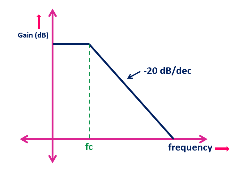
Figure 4: Op-Amp Gain Bandwidth
Slew Rate Distortion in Operational Amplifiers
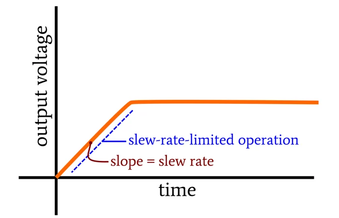
Figure 5: Slew Rate
When an op-amp's slew rate is exceeded, distortion in the output signal becomes apparent, particularly with sine waves. A sine wave smoothly rises and falls, and the fastest change happens at the zero-crossing point. If the sine wave's frequency or strength is too high for the op-amp, the output won't look like the smooth sine wave that went in. Instead, the output turns into a triangular shape because the op-amp can’t change its output fast enough to keep up with the input.
This triangular output is a clear sign of what's known as slew rate distortion. This type of distortion is a problem because it not only changes the shape of the waveform but also introduces unwanted frequencies that can mess up other parts of the circuit. This situation clearly shows how an op-amp can struggle with quick changes in the input signal.
To prevent slew rate distortion, it's important to choose an op-amp with a slew rate that’s higher than the fastest voltage change you expect in your application. Think about both the strength and speed of the signal to figure out the right slew rate. This way, the op-amp can handle quick changes without messing up the output.
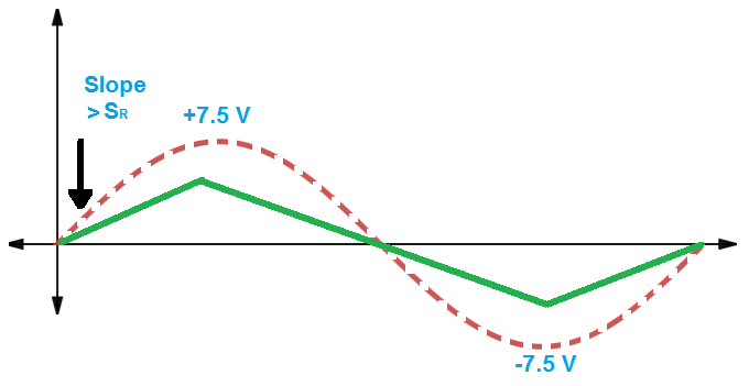
Figure 6: Slew Rate Distortion
Calculating the Required Slew Rate
The formula used to calculate the required slew rate is:
![]()
In this formula:
• ![]() is the highest frequency of the signal you want to amplify (measured in Hertz, Hz).
is the highest frequency of the signal you want to amplify (measured in Hertz, Hz).
• ![]() is the peak voltage of that signal (measured in Volts, V).
is the peak voltage of that signal (measured in Volts, V).
Let’s say you want to amplify a signal that has a peak voltage of 5V and a frequency of 25kHz. You would calculate the slew rate as follows:
![]()
When you multiply these values, you get:
![]()
Finally, compare the calculated slew rate with the specifications of the op-amp you plan to use. The op-amp's slew rate must be at least as high as the calculated value to ensure distortion-free operation.
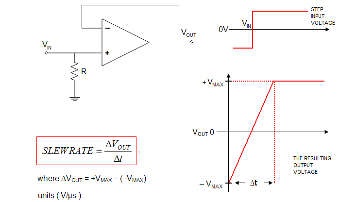
Figure 7: Slew Rate Formula
Here's another example. Imagine you need to drive a sinusoidal signal with the following characteristics:
• Peak-to-Peak Voltage: 5V
• Maximum Frequency: 1 MHz (1 million cycles per second)
Our goal is to calculate the minimum slew rate required for an op amp to handle this signal without distortion.
To break down the values for a 5V peak-to-peak signal, we first calculate the peak voltage. The peak voltage is half of the peak-to-peak voltage. For a signal with a peak-to-peak value of 5V, the peak voltage ( ![]() ) would be 2.5V, as calculated by the formula:
) would be 2.5V, as calculated by the formula:
![]()
Additionally, the maximum frequency ( ![]() ) is provided as 1 MHz.
) is provided as 1 MHz.
The slew rate ( SR ) is a measure of how quickly the output of an op amp can change. To avoid distortion, the slew rate must be fast enough to keep up with the signal. The formula to calculate the slew rate is:
![]()
Let's insert the values into the formula:
![]()
![]()
![]()
This simplifies to:
![]()
So, to ensure your op amp can handle the 5V peak-to-peak signal at a 1 MHz frequency without distortion, it must have a slew rate of at least 15.7 V/μs.
Slew Rate vs. Bandwidth
The connection between slew rate and bandwidth in operational amplifiers is required to their ability to handle high-frequency signals. A higher slew rate allows the output voltage to change more quickly, and can improve the amplifier's bandwidth in some cases. However, a fast slew rate alone does not guarantee a wide bandwidth. Bandwidth is also limited by factors like the op amp's internal compensation and the design of its internal stages. These constraints highlight that while both slew rate and bandwidth are important, they don’t directly equate to one another, and both need to be considered for optimal performance.
When designing circuits, you need to carefully balance slew rate and bandwidth to match the requirements of specific applications. If the slew rate is too low, the amplifier may distort signals that change rapidly, even if the bandwidth seems sufficient on paper. Conversely, an amplifier with limited bandwidth will struggle to accurately amplify high-frequency signals, regardless of its slew rate. This interdependence means that both factors must be evaluated together to prevent issues with signal integrity.
Selecting an operational amplifier requires considering both slew rate and bandwidth together. The chosen op amp must be capable of handling the full dynamic range and frequency spectrum of the input signal to avoid problems like signal distortion or loss.
Figure 8: Bandwidth and Slew Rate
Slew Rate of Different Amplifiers
|
Operational
Amplifier |
Slew Rate (typ)
(V/µs) |
IQ
(typ) (mA) |
Typical
Application |
|
LM741 |
0.5 |
2.8 |
General purpose, audio processing |
|
TL081 |
13 |
3.6 |
Audio and video amplifiers, active filters |
|
OPA2134 |
20 |
4 |
Professional audio equipment, high-fidelity amps |
|
LM324 |
0.5 |
0.8 |
Consumer electronics, sensor amplifiers |
|
AD823 |
30 |
2.8 |
High-speed signal conditioning, ADC drivers |
|
NE5532 |
9 |
8 |
Audio pre-amplifiers, mixing consoles |
|
LT1014 |
0.2 |
0.35 |
Precision instrumentation, DMMs |
|
LM358 |
0.6 |
0.7 |
Low-power applications, battery devices |
|
MCP602 |
2.3 |
1 |
Portable devices, photodiode amplifiers |
|
ADA4898 |
1000 |
10 |
High-speed communication, radar systems |
|
OPA369 |
0.05 |
0.9 |
Low-power portable devices, sensor amplifiers |
|
OPA333 |
0.5 |
0.17 |
Medical instrumentation, precision sensors |
|
OPA277 |
0.8 |
2.5 |
Precision analog processing, test equipment |
|
OPA129 |
1.5 |
6.5 |
High-impedance buffering, medical instruments |
|
OPA350 |
10 |
5.5 |
Video amplifiers, cable drivers |
|
OPA211 |
27 |
3.6 |
High-performance data acquisition, audio amplifiers |
|
OPA827 |
25 |
4.5 |
Audio preamps, ADC buffers, DAC output amplifiers |
|
OPA835 |
560 |
3.9 |
Wideband amplifiers, high-speed signal processing |
|
OPA847 |
6000 |
20 |
RF/IF gain blocks, high-speed communications |
Conclusion
The slew rate is a feature of operational amplifiers that affects how well they handle fast signals and maintain signal clarity. The article discusses various factors influencing slew rate, such as internal compensation, output stage design, and gain bandwidth limitations. It includes a formula for calculating the required slew rate and explores the relationship between slew rate and bandwidth. The article also compares amplifiers based on their slew rates and offers practical advice for matching amplifier capabilities to specific needs, preventing issues like slew rate distortion. Overall, this detailed explanation helps in better understanding op-amps and improving electronic systems.
Frequently Asked Questions [FAQ]
1. What happens if slew rate is high?
When an operational amplifier (op amp) has a high slew rate, it can respond rapidly to changes in its input signal, allowing the output voltage to adjust swiftly. This capability is good for applications requiring quick signal processing, such as video or RF communications. However, a very high slew rate can also present challenges. It can cause oscillations or instability in the circuit in feedback systems. Also, faster transitions may introduce more high-frequency noise into the circuit, potentially from power supply lines or nearby high-speed digital signals.
2. How do you control slew rate?
Controlling the slew rate in an operational amplifier (op amp) involves adjusting the internal configuration of the op amp or modifying the circuit design. One method is to select an op amp with an inherent slew rate that matches the needs of your application, allowing you to prevent issues related to excessive or insufficient speed. Another method is to alter the feedback network by changing resistor or capacitor values that can affect how quickly the op amp responds to input changes, providing a practical way to fine-tune performance without replacing the op amp. External compensation techniques, such as adding bypass capacitors or snubber circuits, can help manage the slew rate by improving stability and reducing unwanted oscillations.
3. Is slew rate a ramp rate?
Yes, the slew rate is often considered a type of ramp rate. It describes the maximum rate at which the output of an op amp can change, and expressed in volts per microsecond (V/µs). This rate is akin to a ramp in that it limits how steep the output voltage can rise or fall, much like a ramp controls the angle of ascent or descent.
4. What is the difference between slew rate and rise time?
Slew rate and rise time are related but distinct parameters in signal processing. Slew rate measures how quickly an operational amplifier's output can change, indicating the maximum rate of change independent of the signal frequency. In contrast, rise time refers to the time it takes for a signal to transition from a specified low value (10%) to a high value (90%) of its maximum amplitude, and it is dependent on the signal's frequency and the system's overall bandwidth. While the slew rate sets a boundary condition for the maximum capability of the output, rise time is an observable characteristic of how a signal behaves within those limits.
5. What is the relationship between slew rate and CMRR?
Slew rate and Common-Mode Rejection Ratio (CMRR) are two different aspects of an operational amplifier's (op amp's) performance. The slew rate deals with how quickly the op amp can respond to changes in the input signal, while CMRR measures how well the op amp can reject noise or interference that affects both inputs equally. Although these two factors are unrelated, they can influence each other in certain situations. For example, in high-speed circuits where the op amp has to respond quickly, a high slew rate might create imbalances in the internal circuits, that could reduce the CMRR and cause errors or distortions.