Mastering the Use of Transistors as Switches
Transistors are fundamental to the world of electronic design, as they power the efficiency and functionality of modern circuits. This article delves into the operating dynamics and applications of bipolar junction transistors (BJTs) in various configurations, emphasizing their important roles in both saturation and cutoff states. The fundamental principles of transistor operation are explored—with particular attention to the transitions between the "on" (saturation) and "off" (cutoff) states—as well as the strategic integration of these components in digital and analog circuits. The discussion extends to practical configurations such as Darlington pairs for higher current applications and the incorporation of transistors into light- and heat-operated switches, emphasizing their versatility in electronic design.Catalog
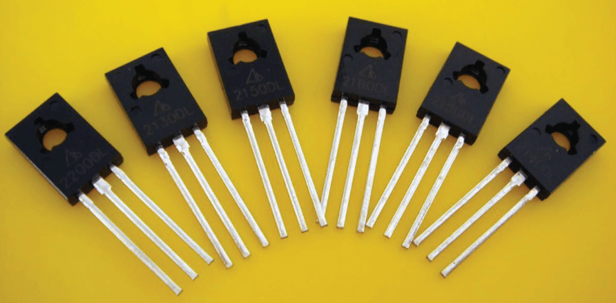
Figure 1: Transistor Switches
How Transistor Switches Work?
Transistors, settling for electronic circuit design, function effectively as switches by operating mainly in two regions: saturation and cutoff. Understanding these regions is key for effective switch functionality.
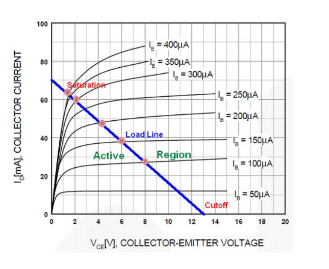
Figure 2: Saturation Region
In the saturation region, the transistor acts like a closed switch. This state is achieved by making sure both the base-emitter and base-collector junctions are forward-biased. Typically, a base-emitter voltage above 0.7 volts drives the transistor into saturation, allowing maximum current flow. The current through the collector (IC) is determined by the circuit parameters (IC = VCC/RL). Here, the voltage drop across the collector-emitter junction is minimal, close to zero, indicating that the transistor is fully "ON" and the current flows freely.
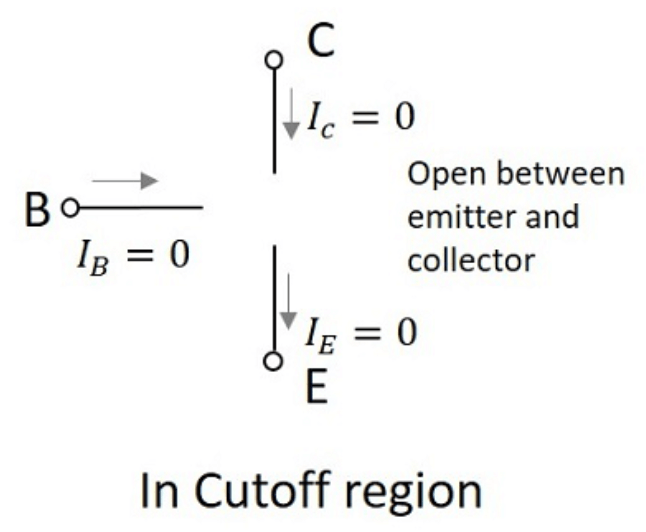
Figure 3. Cutoff Region
In distinction, the cutoff region occurs when there is no base current, leading to no collector current. This state is reached when the transistor's base is at ground potential, making both junctions reverse-biased. As a result, the collector-emitter voltage reaches its maximum, equal to the supply voltage VCC. In this state, the transistor acts like an open switch, effectively blocking any current flow through the circuit.
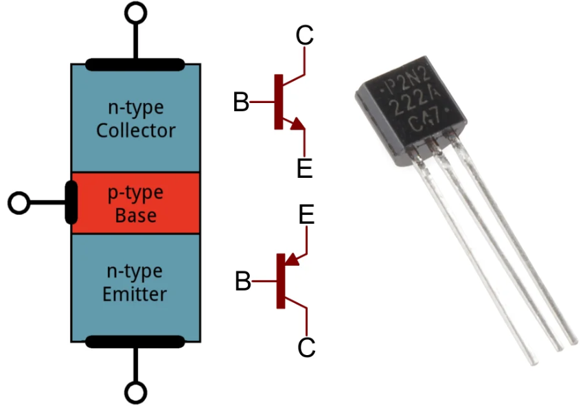
Figure 4: Basic Transistor Circuit
Building a Basic Transistor Circuit
A basic transistor switching circuit often employs the common emitter configuration, designed for efficient switching functionality. The performance of a transistor as a switch depends on its ability to toggle between two states: saturation (fully "ON") and cutoff (fully "OFF").
Saturation State
In the saturation state, the transistor's resistance between the emitter and collector is greatly reduced, allowing maximum current flow through the circuit. This state occurs when the base-emitter and base-collector junctions are forward-biased. The base-emitter voltage must typically exceed 0.7 volts to achieve saturation, ensuring sufficient base current to drive the transistor fully on.
Cutoff State
Equally, in the cutoff state, the internal resistance becomes extremely high, effectively blocking any current flow. This happens when the base-emitter voltage is below the threshold (typically 0.7 volts for silicon transistors), resulting in no base current and, consequently, no collector current.
Leakage Current
Even in the cutoff state, transistors can exhibit minor leakage current. Although minimal, this leakage is decisive in precision circuit design as it can impact overall circuit performance.
Base Resistor Calculation
A grave aspect of designing a switching circuit is calculating the appropriate base resistor (Rb), which regulates the base current (Ib). For example, if the desired base current is 25μA, with a base-emitter voltage of 0.7V, and the input voltage is 3.0V, the base resistor is calculated using Ohm's Law:
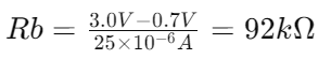
This calculation ensures the base current is sufficient to drive the transistor into saturation, allowing it to function effectively as a switch. Precise resistor values are key for reliable switch operation, emphasizing the detailed considerations necessary in transistor-based circuit design.
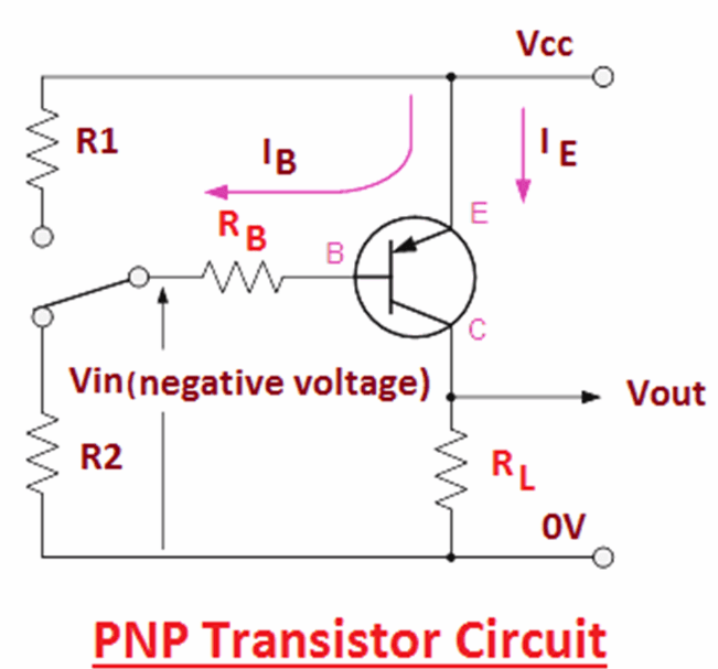
Figure 5: PNP Transistor Switch
PNP Transistor Switch Applications
PNP transistors are effective switches in circuits, similar to NPN transistors, but they differ in their setup and current flow direction. In a distinctive PNP transistor switching configuration, the load is connected directly to the ground, and the transistor controls the power supply to the load.
To activate a PNP transistor, the base needs to be grounded, which is the opposite of the conditions required for NPN transistors. In PNP transistors, instead of sinking the base current, the transistor sources it. Consequently, the collector current flows from the emitter to the collector when the transistor is on.
This reversal is central in designing circuits where current sourcing is advantageous, especially where ground-level switching is practical or required by the circuit’s logic. Understanding these reversed current and voltage requirements is basic for correctly applying PNP transistors in switch roles, enhancing reliability and efficiency.
Base and Emitter Voltage Dynamics
Grounding the base to activate the transistor means the base voltage must be lower than the emitter voltage, typically close to ground potential. This ensures the transistor stays conducting to manage power delivery to the load when the switch is closed.
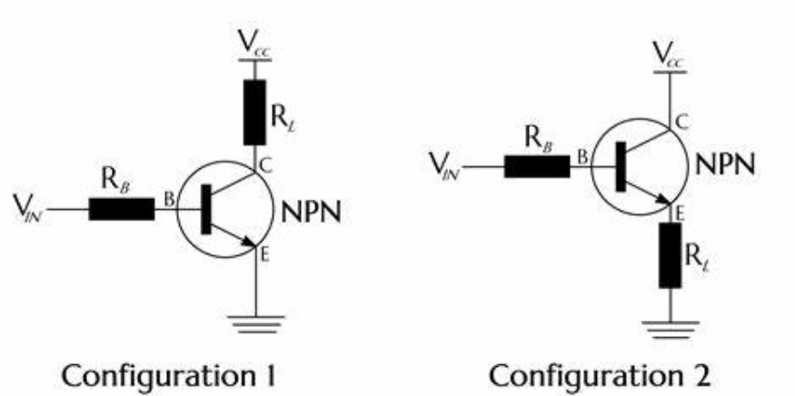
Figure 6: NPN Transistor Circuit
How to Set Up an NPN Transistor Circuit?
In electronic design, NPN transistors are needed in common emitter switching circuits, operating in two primary states: fully "ON" (saturated) and fully "OFF" (cut-off).
When an NPN transistor is saturated, it ideally presents minimal resistance, allowing maximum current flow through the circuit. Nevertheless, in practical applications, a slight saturation voltage still exists, which means there is a small voltage drop across the transistor even when it is fully on.
In the cut-off state, the transistor exhibits very high resistance, effectively halting current flow. Despite this, some minor leakage currents may still occur, which must be accounted for in precise circuit designs.
The operation of NPN transistors as switches is closely linked to the control of the base current. Adjusting the base-emitter voltage is serious, as it dictates the amount of current flowing into the base, thereby regulating the collector current.
Setting a base-emitter voltage around 0.7 volts in a silicon transistor ensures that the base is sufficiently forward-biased. This allows enough current to flow into the base, driving the transistor into saturation. This precise control over the base current and subsequent collector current highlights the transistor's effectiveness as a switch, managing electrical pathways with precision.
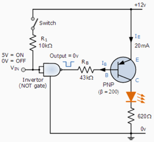
Figure 7: Darlington Transistor Switches
Maximizing Performance with Darlington Transistor Switches
In high-power switching applications, single transistors often lack the necessary current gain to drive a load effectively. Darlington configurations offer a powerful solution by combining two transistors in a cascading arrangement. At this juncture, the emitter of the first transistor feeds directly into the base of the second transistor, significantly amplifying the overall current gain.
Amplifying Current Gain
The Darlington configuration multiplies the current gains of both transistors, resulting in a much higher overall current gain. This is decisive for applications that need robust performance from minimal input currents. A small base current in the first transistor gets amplified, driving the second transistor, which further amplifies the current to drive the load.
Darlington pairs are particularly useful in systems requiring substantial current amplification from low base currents. They are ideal for high-power applications such as inverters, DC motor controls, lighting circuits, and stepper motors. These configurations not only improve switching speeds but also handle higher voltages and currents, making them practical for demanding electronic setups.
Base-Emitter Voltage Considerations
One important aspect of using Darlington transistors is the higher input voltage requirement at the base-emitter junction, typically around 1.4 volts for silicon-based devices. This increase is due to the series connection of the two PN junctions in the Darlington pair. Circuit designers must account for this voltage requirement to ensure effective transistor operation and to fully leverage the high current gain provided by the configuration.
Transistors in Digital Switching
Integrating transistors as switches in digital circuits requires precise calibration of base resistor values. This ensures optimal functionality without compromising the digital logic components. The base resistor regulates the current from the logic gate to the transistor. It's decisive to prevent excessive current, which can damage the transistor or impair circuit performance.
Selecting the correct base resistor value involves considering the output characteristics of the logic gate and the input requirements of the transistor. This includes calculating the maximum current the logic gate can safely output and adjusting the base resistor to limit the transistor's base current. Let's say, if a logic gate outputs 5V and the transistor needs a base current of 1 mA to switch, the base resistor should limit the current to this level, accounting for the voltage drop across the base-emitter junction.
Transistors in digital circuits must operate dependably and effectively, which requires careful integration. It guarantees the system's continued high performance and resilience by safeguarding the transistors as well as the digital logic components. The dependability, switching speed, and response time of the circuit are all improved by properly placing and calculating the base resistor, which raises the overall efficacy of the digital design.
Tips for Using Transistor Switches
When using transistors as switches in electronic circuits, it is needed to operate them in their designated regions: saturation for fully "ON" and cut-off for fully "OFF." This ensures efficient control of devices like lamps, motors, and relays, leveraging small base currents to manage larger collector currents.
For effective performance, transistors must operate distinctly in the saturation and cut-off regions. In saturation, the transistor acts as a closed switch, allowing maximum current flow. In cut-off, it acts as an open switch, preventing current flow.
Handling Significant Currents with Darlington Configurations
In circuits that manage significant currents, using Darlington configurations is advisable. This setup involves a tandem arrangement of two transistors, amplifying the current gain. A small input current at the base of the first transistor controls a much larger output current, making it suitable for high-power applications.
Accurate Component Selection and Circuit Design
Optimal transistor performance relies on selecting components with appropriate current and voltage ratings. Designing the base drive circuitry to keep the transistor within its safe operating area is a high priority. Incorporating protective elements like base resistors and flyback diodes (for inductive loads) further enhances reliability and longevity.
Base resistors limit the base current, preventing damage to the transistor. Flyback diodes protect against voltage spikes when switching inductive loads, safeguarding both the transistor and the circuit.
Figure 8: Bipolar Junction Transistors Switches
Advantages of Using Bipolar Junction Transistors (BJTs) as Switches
Utilizing Bipolar Junction Transistors (BJTs) as switches in electronic circuits offers several substantial advantages.
Efficiency in Power Loss
BJTs are highly efficient in their extreme states—cut-off and saturation. In the cut-off state, there is virtually no current flow. In the saturation state, the voltage drop across the transistor is minimal, resulting in low power dissipation. This efficient energy usage enhances the overall performance of the circuit.
Low-Voltage Operation
BJTs operate at relatively low voltages, enhancing safety by reducing electrical hazards. This low-voltage operation is particularly beneficial in sensitive electronic applications where higher voltages could damage other components.
No Mechanical Wear and Tear
Unlike mechanical switches, BJTs do not suffer from physical degradation. As solid-state devices, they are free from the wear and tear common to mechanical components. This results in greater reliability and a longer lifespan for the device.
Compact and Lightweight
BJTs are compact and lightweight, making them ideal for applications where space and weight are unsafe constraints. Despite their small size, they handle high currents and offer lower conduction losses compared to devices like relays or mechanical switches. This is particularly valuable in high-current applications where efficiency and space utilization are key considerations.
Overall, BJTs provide improved operational efficiency, safety, durability, and performance. They are suitable for a wide range of applications, from small-scale electronics to high-power industrial systems. These practical benefits make BJTs a reliable and efficient choice for various electronic switching needs.
Detailed Dynamics of Transistor Operation in Switching
Transistors function dynamically between two principal states in practical applications: as an open switch in the cut-off region and as a closed switch in the saturation region.
In the cut-off state, both the base-emitter and base-collector junctions are reverse-biased. This inhibits current flow, effectively isolating the collector from the emitter and minimizing power dissipation, rendering the transistor "OFF."
On the other hand, in the saturation region, both junctions are forward-biased, allowing maximum current flow. The collector saturation current (ICSAT) flows freely through the transistor, making it fully "ON." This state is needed for ensuring uninterrupted circuit continuity, allowing the transistor to efficiently relay power or signals across the circuit.
The transition between these states and maintaining them under varying electrical conditions is fundamental to using transistors as switches effectively. This requires careful management of base current and voltage levels to ensure accurate and prompt switching according to the circuit's operational demands.
Benefits of Transistor Switches in Contemporary Electronic Design
Transistor switches are fundamental in modern electronics, offering superior efficiency, reliability, and adaptability. These advantages make them required components over traditional mechanical switches.
Reduced Power Dissipation: Transistor switches exhibit significantly reduced power dissipation.
Effective Low-Voltage Operation: Transistor switches operate effectively at low voltages. This conserves energy and minimizes the risk of voltage-related hazards, enhancing operational safety.
Durability and Longevity: Unlike mechanical switches, transistors have no moving parts and are therefore not subject to physical wear, extending the life of the transistor and reducing the need for maintenance.
High Current Management: Transistors can manage high currents, making them requisite in various applications, from small consumer gadgets to large-scale industrial machinery. Their ability to handle high currents while maintaining minimal power loss is a key advantage.
Compact Size: The compact size of transistor switches allows for sleeker and more efficient designs in electronic circuitry. This small form factor is especially beneficial for creating more streamlined and space-efficient electronic devices.
Exploration of Transistors in Switching Applications
Transistors are requisite in modern electronics, particularly as switches in various practical applications. Their versatility and serious role in control systems are evident in multiple scenarios.
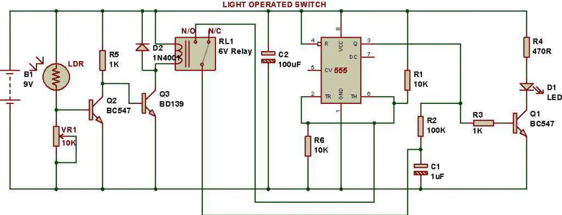
Figure 9: Light-Operated Switches
Light-Operated Switches
In light-operated switches, transistors control lighting systems in response to ambient light changes. Light-dependent resistors (LDRs) serve as sensors, adjusting the base current in the transistor based on light intensity. This modulation changes the transistor's state, turning the lighting system on or off as needed. This automated solution adapts to environmental lighting conditions seamlessly.
Figure 10: Heat-Operated Switches
Heat-Operated Switches
Heat-operated switches use thermistors, which change resistance with temperature variations. These switches are central in safety and environmental control systems, such as fire alarms. When the temperature rises significantly, the thermistor alters the transistor's base current, triggering the alarm. This rapid response to temperature changes highlights the importance of transistors in perilous safety applications.
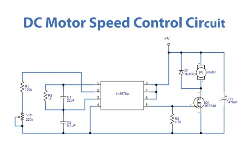
Figure 11: DC Motor Control Circuit
DC Motor Control Circuits
In DC motor control circuits, transistors manage the motor's operational state by switching its power supply on or off, or by controlling its speed and direction based on input signals. This precise control is a necessity in applications ranging from robotic systems to consumer electronics, ensuring functionality and performance.
Conclusion
Through the analysis, it is evident that transistors, especially BJTs, are instrumental in modern electronic design, offering a myriad of benefits over traditional mechanical switches. Their ability to operate efficiently in extreme states—saturation and cutoff—minimizes power loss and maximizes performance, a central advantage in energy-sensitive applications. What' more, their integration into systems like DC motor controls, light-sensitive switches, and temperature-dependent alarms underscores their adaptability and indispensability in a broad spectrum of applications. This comprehensive discussion fosters a deeper understanding of transistor operations and their key role in circuit design. It also accentuates their impact on the robustness, efficiency, and innovation in electronic system development, making them a cornerstone of contemporary electronics and a driving force behind technological progress.
Frequently Asked Questions [FAQ]
1. How transistor work as an open switch?
A transistor works as an open switch when it is in the "off" state, meaning it does not allow current to flow between the collector and the emitter. This occurs when the base-emitter voltage is below a certain threshold (for bipolar junction transistors) or when the gate-source voltage is insufficient (for field-effect transistors). In this state, the transistor effectively isolates the circuit components connected to its collector and emitter, preventing electrical current flow, similar to how a mechanical switch would be in the "off" position.
2. Can a transistor be operated as an electronic switch?
Yes, a transistor can effectively function as an electronic switch. It does this by alternating between saturation (fully on) and cutoff (fully off) states. In the saturation state, the transistor allows maximum current to flow between the collector and the emitter, behaving like a closed switch. In the cutoff state, it blocks current flow, acting like an open switch. This switching capability is utilized in various applications, including digital circuits and pulse width modulation (PWM) systems.
3. How to use a transistor as the switch for the motor?
To use a transistor as a switch for controlling a motor, you'll need to set up the transistor in a circuit where it can handle the current requirements of the motor. Here's a straightforward approach:
Select an appropriate transistor: Choose a transistor that can handle the motor’s current and voltage requirements.
Circuit setup: Connect the emitter (for an NPN transistor) or the source (for an N-type MOSFET) to the ground. Connect the motor between the power supply (matching the motor's rated voltage) and the collector (or drain).
Control connection: Connect a control signal (from a microcontroller or another control circuit) to the base (or gate) of the transistor through a suitable resistor to limit current.
Operation: Applying a sufficient voltage to the base or gate turns the transistor on, allowing current to flow and the motor to operate. Removing the signal turns the transistor off, stopping the motor.
4. How do you use a transistor as a switch?
Using a transistor as a switch involves wiring it to control a load (like an LED, motor, or another electronic device) with a control signal. Here's the basic method:
Connect the load: Attach one end of the load to the power supply and the other end to the collector (NPN) or drain (MOSFET).
Base/Gate connection: Attach the base or gate to the control signal source through a resistor.
Emit/Source to the ground: Connect the emitter (NPN) or source (MOSFET) to the ground.
Control the signal: Varying the control signal between high and low states will switch the transistor between conducting and non-conducting states, controlling the load accordingly.
5. Can a transistor act as a switch or an amplifier?
Yes, a transistor can function both as a switch and as an amplifier, depending on how it is configured in the circuit:
As a switch: When configured to operate between cutoff (off state) and saturation (on state), it acts as a switch.
As an amplifier: When configured in the active region (partially on), the transistor amplifies the input signal at the base, with a corresponding amplified output at the collector.
These uses demonstrate the versatility of transistors in electronic circuits, able to either regulate signal intensity or simply act as binary devices switching between on and off states.