Mastering Buzzer Mechanics: A Comprehensive Guide to Technologies, Tones, and Circuits
Buzzers are influential in numerous devices, from simple household items to complex industrial machines, primarily functioning as useful sound-producing elements. This article explores the main types of buzzers, specifically piezo and magnetic variants, detailing their operational principles and specialized uses. Piezo buzzers, valued for their efficiency and durability, utilize the piezoelectric effect, converting voltage applied to piezoelectric materials into sound, making them suitable for energy-sensitive and space-limited applications. This also discusses the feedback mechanisms in piezo buzzers that improve their effectiveness and the role of buzzers as indicators and transducers in various settings. In addition, it examines sophisticated circuit designs that enhance buzzer functionality, accommodating a broad range of applications from simple alerts to intricate warning systems.
Catalog

Figure 1: Buzzers
Exploring Buzzer
Buzzers, which are components that utilize DC voltage to emit sound, are integral to numerous devices. They come in two main types: piezo and magnetic buzzers. Each type is crafted for distinct purposes and exhibits unique operational characteristics.
Piezo buzzers are valued for their efficiency and longevity. They use piezoelectric materials that create sound when a voltage is applied. This type of buzzer is ideal for applications requiring reliable performance over time. Magnetic buzzers operate on electromagnetic principles. When electric current passes through a coil, it generates a magnetic field. This field moves a metal diaphragm, resulting in sound production. Magnetic buzzers are suitable for applications needing a robust sound output.
The design and technology of each buzzer type influence the variety of sounds they can produce, ranging from simple beeps to complex tones. Used in alarm systems to provide clear and immediate alerts. Serve as feedback tools in user interfaces, enhancing user interaction with devices.
Comparing Magnetic and Piezo Buzzers
Buzzer technology primarily consists of two types: magnetic buzzers and piezo buzzers. Each has unique mechanics and specific application considerations. The choice between them depends on voltage and current requirements, desired sound intensity, and physical constraints of the device.
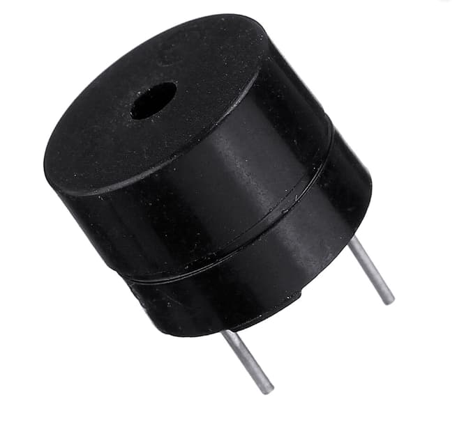
Figure 2: Magnetic Buzzers
Magnetic buzzers operate on lower voltage ranges, typically from 1.5 to 12 volts, but they require higher current, often exceeding 20 milliamperes. They generate sound through the movement of a ferromagnetic disk. An electric current flows through a coil. This current creates a magnetic field. The magnetic field pulls a ferromagnetic disk toward the coil. When the current stops, the disk snaps back, producing a sharp, distinct sound.
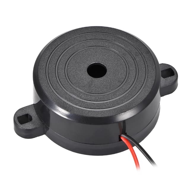
Figure 3: Piezo Buzzers
Piezo buzzers function optimally at higher voltages, up to 220 volts, but they draw significantly less current, generally below 20 milliamperes. Voltage is applied to the piezoelectric disk. The disk deforms due to the voltage. This deformation causes rapid vibrations. The vibrations generate sound waves. Piezo buzzers are ideal for applications needing efficient power consumption and longer operational life.
Feedback Mechanisms in Piezo Buzzers
Piezo buzzers use advanced feedback mechanisms to improve performance and reliability. These mechanisms streamline their operational circuits and optimize sound production.

Figure 4: Segmented Piezo Element
A key feature is the segmented piezo element. This element is divided into sections, with one part dedicated to feedback sensing. When the primary piezo element is activated, it starts to vibrate. The vibration mechanically influences the feedback segment. This influence induces a voltage in the feedback segment. The induced voltage is fed back into the driving circuit.
The feedback voltage typically goes to the base of a transistor within the circuit. The transistor dynamically adjusts the driving signal based on the feedback, creating a self-regulating loop. This loop ensures the transistor modifies the driving signal in real time to match the optimal vibration frequency. Continuous adjustments maintain stable and consistent sound output. The system avoids frequencies that cause mechanical stress, improving efficiency and extending the buzzer's lifespan.
Transducers and Indicators: Key Functions and Uses
Buzzers are generally divided into two main types: indicators and transducers. Each type is designed for specific applications and has distinct operational characteristics.
Indicators come with integrated driving circuits, making them easy to install and use. The built-in circuitry simplifies installation. They emit sound at a preset frequency, ensuring consistent and predictable alerts. Ideal for basic consumer appliances and routine alarms where simplicity and reliability are desperate. Simple to install with minimal maintenance. Fixed sound output, suitable for straightforward applications.
Transducers, on the other hand, do not have internal driving circuits, allowing for more customization. They need an external driving signal, which can be adjusted for specific sound needs. Offer extensive control over sound characteristics. Require additional design time and external components.
The Spectrum of Buzzer Tones
Buzzers can generate a wide range of tones, from simple continuous signals to complex sequences like sirens or chimes. Their design as indicators or transducers determines the variety and complexity of sounds, they produce.
Indicators have built-in driving circuits, which limit their operation to basic modes. Operate on a fixed voltage, emitting constant tones or simple on-off pulses. Suitable for basic auditory feedback, such as in-timers or simple alerts in household appliances. Fixed sound output, ideal for straightforward applications. Restricted to basic tones due to built-in circuits.
Transducers, requiring external driving circuits, offer more advanced sound capabilities. Allow manipulation of complex waveforms and varied sounds. Can generate tones that rapidly shift in frequency or intensity, mimicking emergency sirens or musical chimes. Basic in environments where specific sounds correspond to particular actions or alerts, such as medical equipment, automotive warnings, and security systems. Capable of producing a wide range of complex sounds. Can be programmed for various auditory patterns, suitable for advanced applications.
Operating Principles of Buzzers
Buzzers, specifically piezo and magnetic types, use different physical phenomena for sound production. Each type is optimized for specific applications based on their unique properties.
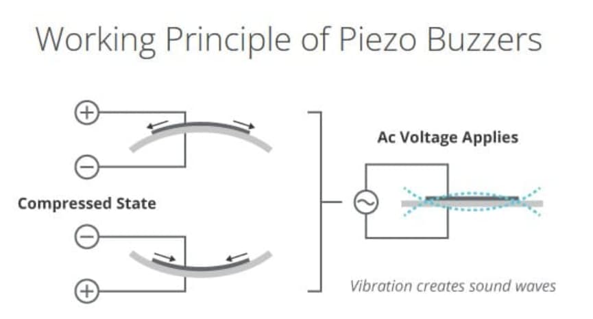
Figure 5: Piezo Working Principle
Piezo buzzers work through the piezoelectric effect, utilizing materials that generate an electric charge when stressed. An alternating current (AC) is applied to a piezoelectric material, typically a ceramic disc. The AC voltage causes the piezoelectric material to expand and contract due to the electric fields aligning its molecular structure. The rapid deformation and relaxation of the material create vibrations, which produce sound waves emitted directly from the material's surface. Ideal for medical alert systems and portable electronics due to their small size and low voltage requirements. Produce clear and precise tones, suitable for applications where sound fidelity is influential.
Magnetic buzzers operate based on electromagnetic principles involving a coil and a movable metal part, often a disk. A direct current (DC) flows through an electromagnetic coil, creating a magnetic field. The magnetic field attracts a nearby metal disk. When the current stops, the magnetic field collapses, causing the disk to snap back to its original position, producing a sound wave through mechanical vibration. Suitable for noisy environments like industrial settings due to their loud and robust sound. The simple design and fewer moving parts ensure longevity and reliability.
Key Buzzer Specifications: Selection Criteria
Choosing the right buzzer involves considering several key specifications that affect its performance and suitability for specific applications. These specifications include frequency response, sound pressure level (SPL), resonant frequency, impedance, and physical configuration. Each plays a vibrant role in the buzzer's functionality.
|
Key Buzzer Specifications |
|
|
Frequency Response |
Frequency response indicates the range of
frequencies a buzzer can emit effectively. This is settling for applications
requiring clear and recognizable sounds. A buzzer with a wide frequency
response can produce the needed tones consistently and clearly. |
|
Sound Pressure Level (SPL) |
SPL measures the loudness of the buzzer's
output in decibels (dB). Higher SPL is beneficial in noisy environments where
the buzzer must be audible over other sounds. |
|
Resonant Frequency |
The resonant frequency is the frequency
at which the buzzer vibrates most efficiently. Operating near this frequency
maximizes acoustic output while minimizing power consumption, making it
beneficial for battery-powered devices. |
|
Impedance |
Impedance reflects the buzzer's
resistance to electrical current at its resonant frequency. Matching the
buzzer's impedance with compatible driving circuits ensures optimal
performance and prevents potential damage. |
|
Physical Configuration and Mounting
Style |
The buzzer's physical configuration,
including its mounting style, impacts its acoustic properties and ease of
installation. The mounting style influences how sound waves propagate,
affecting overall sound quality and volume. |
Types of Buzzers
Buzzers come in various types beyond the basic piezo and magnetic models. These include electromagnetic, mechanical, and electromechanical buzzers, each designed for specific applications with unique characteristics.
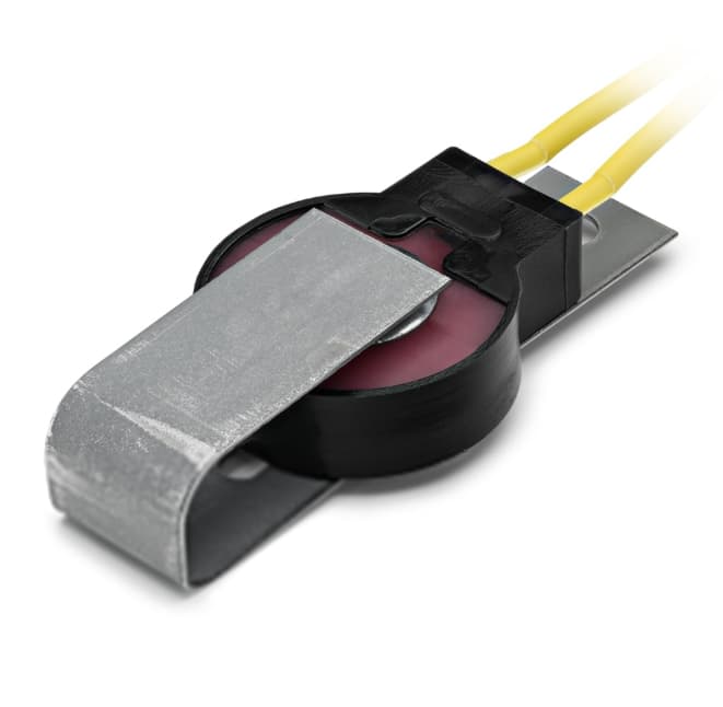
Figure 6: Electromagnetic Buzzers
Electromagnetic buzzers work similarly to magnetic buzzers but are tuned to operate at a specific frequency. Designed to provide a stable and reliable sound signal. Ideal for timed alerts and simple signaling devices where uniform sound is needed.
Figure 7: Mechanical Buzzers
Mechanical buzzers generate sound using external mechanical components like hammers or springs. The mechanical action is effective in noisy environments. Produces a unique sound that can easily stand out. Suitable for settings requiring durable and distinguishable sound output.

Figure 8: Electromechanical Buzzers
Electromechanical buzzers combine mechanical and electromagnetic technologies. Offers the durability of mechanical systems and the flexibility of electromagnetic designs. Capable of producing varied sound patterns with strong output. Used in consumer electronics and industrial alarm systems where different sound patterns and high output are required.
Designing Application Circuits for Magnetic and Piezo Indicators
A basic application circuit for both magnetic and piezo indicators involves directly connecting them to a DC voltage source. This simple setup is effective for producing continuous or pulsed sound outputs, making it ideal for straightforward alert systems in consumer electronics and appliances.
Magnetic Indicators: connecting to a DC source enables consistent sound production as long as power is supplied. The operation involves electrical current flowing through a coil. The current generates a magnetic field. The magnetic field repeatedly pulls and releases a metal disk, creating sound.
Piezo Indicators: when connected to a DC source, typically emit a single tone or pulse. The operation includes voltage applied to the piezo element. The piezo element deforms, creating a sound wave. The element returns to its original shape when the voltage is removed, generating another sound wave.
This straightforward approach to buzzer circuit design provides several advantages. First, its ease of integration due to simple connections makes it readily incorporable into various devices. It also offers reliability with minimal components to ensure consistent performance. In addition, the design is characterized by low power consumption, efficiently using power while still providing adequate sound for alerts and notifications. This setup proves especially suitable for timers, alarms, and notification systems by providing clear, reliable, and distinct audible signals. By employing a direct connection to a DC voltage source, the streamlined design ensures effective sound production with minimal complexity, making it ideal for a broad array of applications.

Figure 9: Circuit for Magnetic Transducer
Techniques for Magnetic Transducer Application Circuits
The application circuit for a magnetic transducer is more complex than basic buzzers, requiring specific waveforms for effective operation. This setup allows precise control of sound output through various waveform shapes, managed by electronic switches like Bipolar Junction Transistors (BJTs) or Field-Effect Transistors (FETs).
To generate different waveforms, engineers program transistors to switch on and off at controlled intervals. This process involves transistors turning on and off at set times. This switching generates waveforms, from simple square waves to complex modulated signals. The ability to shape waveforms allows for diverse sounds, such as steady beeps, escalating alarms, or varying tones.
BJTs or FETs are chosen as switching components for their efficiency and reliability. Their selection is based on the effective handling of current loads and voltage levels. Long-term reliability in continuous operation. Matching the expected current and voltage requirements of the circuit.
Crafting Effective Circuits for Piezo Transducers
The application circuit for a piezo transducer can be simpler than that for magnetic transducers due to the electrical characteristics of piezo materials. Piezo transducers have lower inductance, allowing for efficient operation with less complex circuits. However, this simplicity can lead to higher power dissipation, so careful circuit design is used to reduce energy loss.
To optimize the performance of a piezo transducer, the driving circuit is typically equipped with waveform generators that create precise voltage patterns useful for the desired sound output. It also incorporates basic components such as resistors, capacitors, and transistors, which help shape the electrical signal to maximize acoustic output without consuming excessive power. Additional components, including diodes and voltage regulators, are integrated to enhance efficiency by protecting the circuit from voltage spikes and stabilizing the voltage. This safeguards the piezo element from over-voltage, which can degrade performance over time.
This tailored approach ensures that piezo transducers deliver optimal sound quality and volume, making them suitable for a variety of applications. For instance, electronic beepers are commonly used in devices like microwaves and watches, while medical alert devices utilize these transducers to produce detailed sound patterns for effective alerts. The benefits of an efficient circuit design include power conservation, which reduces energy loss, an extended lifespan that ensures reliable operation over time, and optimal performance characterized by high-quality sound output.
Mastering Full Bridge Circuits for Piezo Transducers
For applications requiring high sound output, using a full bridge circuit to drive piezo transducers is highly effective. This configuration doubles the voltage across the transducer, maximizing acoustic pressure and volume.
A full bridge circuit consists of four switches, usually transistors or MOSFETs, arranged to allow a higher voltage swing across the piezo device. The key steps are four switches are set up in a specific configuration. Alternating the activation of these switches reverses the polarity of the voltage applied to the piezo element. This setup effectively doubles the peak-to-peak voltage compared to half-bridge or direct-drive configurations.
The benefits of increased voltage swing significantly enhance the sound output by boosting acoustic pressure, which generates louder and more penetrating sounds, and improving efficiency, as it converts energy more effectively into sound while reducing power waste. The full bridge circuit is particularly ideal for scenarios where robust sound output is influential, such as in alarm systems that ensure loud, clear alerts in emergencies, and high-visibility notification devices that provide strong auditory signals for attention-grabbing notifications. In addition, the full bridge setup not only amplifies sound volume but also reduces power waste and enhances reliability, improving performance in demanding environments.
Conclusion
Throughout this comprehensive review of buzzer technologies, it becomes evident that the choice between piezo and magnetic buzzers hinges on a nuanced understanding of their distinct properties and the specific demands of their intended applications. Piezo buzzers, with their ability to produce clear and precise tones, are particularly suited to compact devices and situations where sound clarity is serious. On the other hand, magnetic buzzers, characterized by their ability to generate louder and more durable sound outputs, prove requisite in noisy, demanding environments.
The integration of sophisticated circuit designs, such as full bridge circuits for piezo transducers, further underscores the capacity of these components to meet diverse operational demands, enhancing both efficiency and sound output in dangerous applications. Overall, the evolution of buzzer technology continues to be driven by a blend of scientific innovation and practical application needs, ensuring that these components not only meet but exceed the performance expectations in various technological landscapes.
Frequently Asked Questions [FAQ]
1. What are the basics of a buzzer?
A buzzer is an audio signaling device, which can be mechanical, electromechanical, or piezoelectric. Commonly used in alarms, timers, and confirmation of user input like keystrokes, buzzers generate sound based on an internal oscillation source which produces regular beeps when powered.
2. What is the purpose of a buzzer in a circuit?
The primary purpose of a buzzer in a circuit is to provide an audible alert or signal to a user. This can indicate that a certain condition has been met, such as a timer reaching zero, a user input is recognized, or a fault condition in equipment.
3. What are the advantages of a buzzer?
Buzzers are compact, cost-effective, and reliable for producing sound. They require very little power to operate, making them ideal for portable and low-power electronic devices. Their distinctive sounds can be heard even in noisy environments, aiding in effective alerting.
4. How do you use a buzzer system?
To use a buzzer, connect it to a power source and a control mechanism, such as a switch or a microcontroller, in your circuit. The control mechanism can activate the buzzer based on specific conditions or inputs. This setup is used in a variety of applications from household appliances to industrial systems.
5. How to connect a buzzer to a simple circuit?
To connect a buzzer in a simple circuit:
Identify the positive and negative leads of the buzzer.
Connect the positive lead to one of the output pins of a battery or power supply.
Attach the negative lead to the ground or negative terminal of the power source.
Include a switch between the power source and the buzzer to control the activation of the buzzer manually.