Learn the basics: resistance, inductive reactance, capacitive reactance, and impedance
In electrical engineering, a variety of physical quantities, including resistance, inductive reactance, capacitive reactance, and impedance, are frequently encountered. The circuit is often observed to be resistive, inductive, and capacitive. Under specific conditions, the circuit may also display a resonant state. In the following discussion, we will compare and contrast the variations and interrelationships among these physical quantities and the characteristics exhibited by the circuit upon their integration.
resistance
The flow of electricity through a conductor encounters resistance, which is a measure of the conductor's opposition. A larger obstruction results in greater resistance, while a smaller obstruction yields less resistance. While all substances exhibit resistance, varying levels exist, affecting their ability to impede electrical current. Insulators are used to isolate conductors and protect against electric shock due to their superior ability to block current. On the other hand, superconductors exhibit almost zero resistance.
Resistors are commonly depicted by the letter R and the resistance is an intrinsic characteristic of the conductor itself, independent of external factors. In other words, once a resistor is manufactured, its resistance value is set and remains unaffected by external factors. This is known as the law of resistance and is expressed by the following formula:
R=ρL/S
ρ——The resistivity of the material used to make the resistor, the international unit is ohm·meter (Ω·m);
L——The length of the wire wound into a resistor, the international unit is meters (m);
S——The cross-sectional area of the wire wound into a resistor, the international unit is square meters (m²);
R——Resistance value, the international unit is ohm, referred to as ohm (Ω).
The resistance of a resistor is the same in both AC and DC circuits and does not change with changes in the power supply frequency.
Resistance
In an AC circuit, the inductor coil resists the current through its inductive reactance. The magnitude of inductive reactance can be calculated using the following formula.
XL= ωL = 2πfL
XL is the inductive reactance, in international units of ohms (Ω);
ω is the angular frequency of alternating current (AC), the international unit is rad/s (rad);
f is the frequency of alternating current, the international unit is hertz (Hz);
L is the inductance of the inductor coil, the international unit is Henry (H).
Obviously, the size of the inductive reactance depends not only on its own coefficient (L), but also on the externally applied alternating current angular frequency (ω) or frequency (f).
The higher the inductance L of an inductor coil, the greater the inductive reactance XL.
Similarly, the higher the angular frequency ω or frequency f of the alternating current, the higher the inductive reactance XL. The inductor coil has the characteristic of allowing low frequencies to pass while hindering high frequencies.
Assuming DC has a frequency of zero, the inductive reactance is also zero with no obstruction to DC.
Capacity resistance
In an AC circuit, the impeding effect of a capacitor on current flow is capacitive reactance. The size of capacitive reactance is expressed by the formula as follows:
XC= 1/(ωC) = 1/(2πfC)
XC is the capacitive reactance in ohms (Ω);
ω is the angular frequency of alternating current, in radians per second (rad/s);
f is the frequency of alternating current, the international unit is Hertz (Hz);
C is the capacitance of the capacitor, the international unit for the farad (F).
Obviously, the size of the capacitive resistance is not only related to its own factor (C), but also to the angular frequency (ω) or frequency (f) of the external AC current.
The larger the capacitance C of the capacitor, the smaller the capacitive reactance XC.
The higher the angular frequency ω or frequency f of the alternating current, the smaller the capacitive reactance XC, the smaller the impedance of the alternating current, that is, the capacitor has a high-frequency resistance to low-frequency characteristics.
DC frequency we can think of as zero, so the capacitive impedance is infinite, the impedance of DC is also infinite, which is the capacitor has the characteristics of insulation of direct current AC.
Impedance
In a circuit with resistance, inductance, and capacitance, the resistance to alternating current is called impedance. Impedance is often written as Z. The international unit of impedance is the ohm (Ω).
Impedance consists of resistance, inductance, and capacitance, but is not a simple addition of the three. For a given circuit, impedance is not constant, but varies with frequency.
The following describes series and parallel circuits composed of resistance, inductance, and capacitance, the magnitude of their impedance, and the nature of the circuit.
RLC series circuit
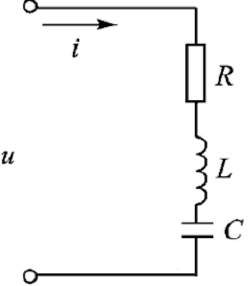
RLC series circuit
The circuit is shown above.
Since R, L and C are in series, the currents flowing through R, L and C are the same are i.
Impedance, voltage and power are related by the triangle shown below.
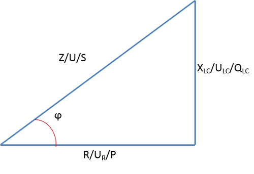
Relationship between impedance, voltage and power
Where Z is the total impedance of the RLC series connection, XLC = XL-XC, is the inductive and capacitive reactance synthesized reactance; U is the total voltage of the RLC series connection, ULC = UL-UC, is the voltage on the inductance and capacitance synthesized voltage; S is the apparent power of the RLC series circuit, the international unit of volts-ampere (VA), QLC = QL-QC is the reactive power on the inductance QL is the reactive power synthesized with the reactive power QC on the capacitor, and the international unit of reactive power is spent (var); P is the active power, and the international unit is watt (W).
The angle ϕ between Z/U/S and R/UR/P is the power factor angle.
When XLC=XL-XC>0, or the inductive reactance XL is greater than the capacitive reactance XC, the voltage divided by the inductor is greater than the voltage divided by the capacitor, and the circuit is inductive, and the inductive circuit triangle is shown below:
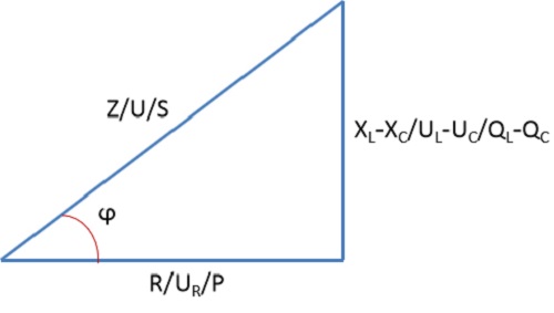
Inductive Circuit Triangle
When XLC=XL-XC<0, or the inductive reactance XL is less than the capacitive reactance XC, the voltage divided by the capacitor is greater than the voltage divided by the inductor, and the circuit is capacitive, and the capacitive circuit triangle is shown below:
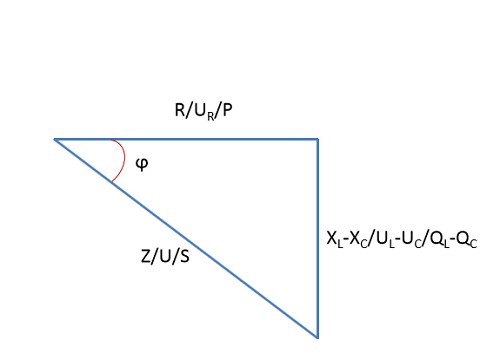
Capacitor Circuit Triangle
When XLC=XL-XC=0, or the inductive impedance XL is equal to the capacitive impedance XC, the circuit is resistive and the circuit undergoes series resonance, at which point the total impedance, Z=R, is the state of least impedance for the RLC series circuit. Using this point, in electronic circuits, the RLC series to do a certain frequency trap, that is, in the vicinity of a certain frequency, the impedance of the trap to the frequency of the smallest, and thus bypass the signal near the frequency.
The characteristic curve of the trap is shown below, when f=f0, series resonance occurs, Z=R, and the impedance is minimized.
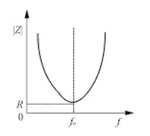
Characteristic curves of traps
RLC parallel circuit
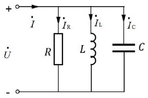
RLC parallel circuit
The circuit is shown above.
Since R, L and C are connected in parallel, the voltages applied to R, L and C are the same all are u. The voltage of R, L and C is the same.
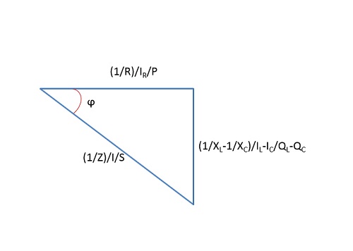
Impedance, current and power are related by the triangle shown below.

Relationship between impedance, current and power
Where Z is the total impedance of the RLC parallel circuit, 1/XLC=1/XL-1/XC; I is the total current of the RLC parallel circuit, ILC=IL-IC, the current synthesized by the current flowing through the inductor and the current flowing through the capacitor; S is the apparent power of the RLC parallel circuit, the international unit of volts-ampere (VA), and QLC=QL-QC is the reactive power of the reactive power on the inductor, QL and the reactive power synthesized by the reactive power on the capacitor, and the international unit of reactive power is spent (var); P is the active power, the international unit of watts (W). QC the reactive power synthesized from the reactive power QC on the capacitor, the international unit of reactive power is spent (var); P is the active power, the international unit is watt (W).
The angle ϕ between (1/Z)/I/S and (1/R)/IR/P is the power factor angle.
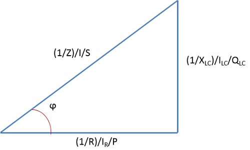
When 1/XLC=1/XL-1/XC>0, or when the capacitive reactance XC is greater than the inductive reactance XL, the current flowing through the inductor is greater than the current flowing through the capacitor, and the circuit is electrically inductive, and the inductive circuit triangle is shown below:
Inductive Circuit Triangle
When 1/XLC=1/XL-1/XC<0, or the inductive reactance XL is greater than the capacitive reactance XC, the current flowing through the capacitor is greater than the current flowing through the inductor, and the circuit is capacitive, and the capacitive circuit triangle is shown below:
Relationship between impedance, current and power
When XLC = XL-XC = 0, or the inductive impedance XL is equal to the capacitive impedance XC, the circuit is resistive, the circuit occurs in parallel resonance, at this time, the total impedance Z = R, for the RLC parallel circuit impedance maximum state. Using this point, in electronic circuits, RLC parallel to do a certain frequency frequency selector, that is, in the vicinity of a certain frequency, the frequency selector of the frequency impedance is the largest, the best selectivity for signals near the frequency.
That covers everything in this article. If you have any questions, please feel free to contact us. allelcoelec will reply to you promptly.