Innovative Guide to JK Flip-Flops: Analyzing Truth Tables, Mechanisms, and Strategic Applications
This article explores the architecture, operation, and diverse applications of the JK flip-flop, starting from its basic structure and input-output relations, through detailed operational mechanics, to its strategic implementations in complex digital systems. The discourse extends to distinguishing between the edge-triggered and level-triggered variants, analyzing their respective utilities in synchronous and asynchronous environments.Catalog
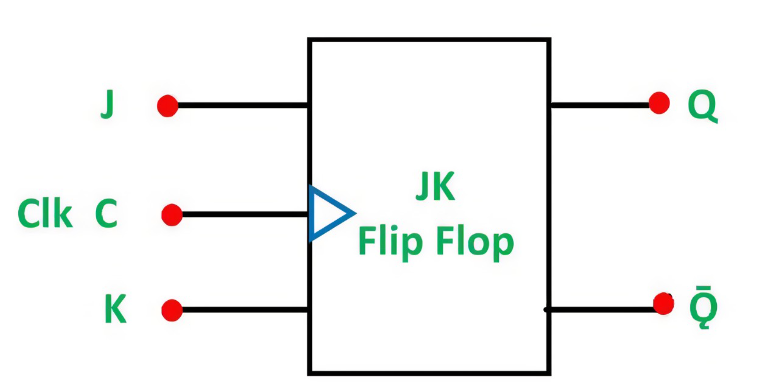
Figure 1: JK Flip-Flop
Basics of JK Flip-Flop
The JK flip-flop is a basic component in digital electronics, designed to store a single bit of information. It builds on the simpler SR flip-flop by adding feedback, which helps prevent errors known as "race conditions," where the output becomes unstable.
This flip-flop has two main inputs, J (set) and K (reset), and two outputs: Q and its complement, Q'. These outputs continuously reflect the current state and its opposite, allowing the circuit to adjust and respond to real-time input changes.
The JK flip-flop operates in specific ways based on the input values:
• When both J and K are 0: The flip-flop holds its current state. No changes occur.
• When both J and K are 1: The flip-flop toggles its state. If Q is 0, it becomes 1; if Q is 1, it switches to 0. This toggle action is a key feature that distinguishes the JK flip-flop from simpler designs.
• When J is 1 and K is 0: The flip-flop sets its state, making Q equal to 1.
• When J is 0 and K is 1: The flip-flop resets, making Q equal to 0.
Operation of the JK Flip-Flop
The JK flip-flop plays a key role in digital circuits by managing memory and timing through a coordinated response to input signals and clock pulses. Its operation depends heavily on the timing of the J and K inputs relative to the clock signal, which determines how the output states (Q and Q̅) change. This synchronization ensures that the flip-flop behaves predictably in various circuit applications. The flip-flop relies on NAND or NOR gates to manage these state changes.
Holding the Current State - When both J and K inputs are low (0), the flip-flop keeps its current state. The logic gates effectively "lock" the outputs, ensuring the previous state (either high or low) is maintained. This holding function is serious in applications where data must remain stable until a specific change is a must.
Setting the Output High (Set State) - When the clock pulse occurs and J is high (1) while K remains low (0), the logic gates adjust to set the flip-flop. This drives the output Q to a high state (1). This is useful in situations where the circuit needs to trigger a high output, for example, activating a device or storing a "1" in memory.
Clearing the Output Low (Reset State) - If J is low (0) and K is high (1) at the time of a clock pulse, the flip-flop transitions to a reset state, forcing Q to go low (0). This resetting action is often used in circuits that need a default or cleared state after completing an operation, such as clearing data from memory.
Toggling the Output - The flip-flop's unique feature emerges when both J and K are high (1). When the clock pulse arrives, the flip-flop toggles, switching the output from its current state to the opposite one. If Q is high, it becomes low, and if Q is low, it becomes high. This toggle function is insistent in applications like counters or devices that need to alternate between states automatically.
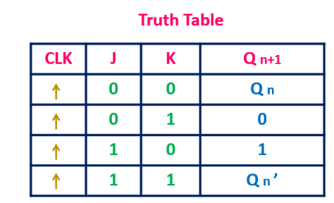
Figure 2: JK Flip-Flop Truth Table
JK Flip-Flop Truth Table Analysis
The truth table of the JK flip-flop is a key tool for visualizing how it reacts to different input signals in sync with clock pulses. This table helps in both designing and troubleshooting digital circuits by showing how the flip-flop's outputs change based on various input conditions.
• Both J and K Low (J=0, K=0): When both inputs are 0, the flip-flop holds its current state. Whether Q is high or low, it stays unchanged. This is noteworthy for circuits where stable data retention is wanted, such as in-memory elements, where preserving the current state is suitable until a specific change is triggered.
• J High, K Low (J=1, K=0): When J is 1 and K is 0, the flip-flop sets the output Q to high (1). This setting condition is useful in applications that require a precise trigger to activate an operation, like turning on a device or initiating a sequence in a logic circuit.
• J Low, K High (J=0, K=1): With J at 0 and K at 1, the flip-flop resets, making Q low (0). This reset function is serious in systems that need to return to a default state, like when clearing data or initializing a process.
• Both J and K High (J=1, K=1): When both inputs are high, the flip-flop toggles its state. If Q is high, it becomes low, and if Q is low, it switches to high. This toggling behavior is substantial for devices that need to alternate between states, such as in frequency dividers or counters.
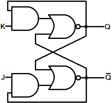
Figure 3: JK Latch
Insights into JK Latch Operation and Uses
The JK latch operates similarly to the JK flip-flop but without the need for a clock signal. Instead of waiting for a clock edge, the JK latch responds continuously to input changes, making it "level-sensitive." This means that as long as the inputs (J and K) are stable, the output will change in real-time, offering immediate feedback based on the input conditions.
Unlike the edge-triggered JK flip-flop, which updates its output only when the clock signal changes (from low to high or vice versa), the JK latch adjusts its output instantly as inputs shift. This constant, real-time responsiveness is valuable in scenarios where immediate action is desired without the delay caused by clock synchronization.
Noise Filters: In digital circuits that need to quickly filter out unwanted noise, the JK latch's instant reaction to input changes is influential. Because it doesn't wait for a clock pulse, it can adjust the output as soon as noise is detected, preventing delays in signal correction.
Simple Memory Elements: The JK latch can serve as a basic memory unit in systems that don't require complex, clocked control. Since the latch keeps the output stable as long as the inputs don't change, it effectively holds the current state, which is useful for circuits needing to retain information without the overhead of clocked operations.
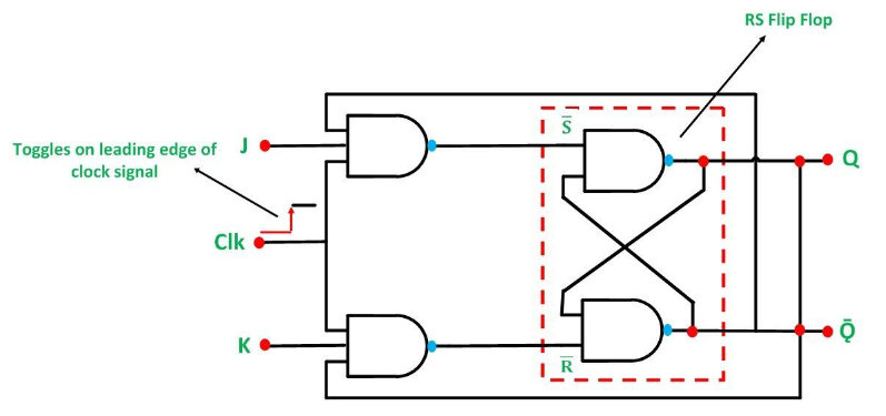
Figure 4: Timing Diagram Analysis for the JK Flip-Flop
Analyzing the Timing Diagram of JK Flip-Flops
A timing diagram of the JK flip-flop provides a visual breakdown of how the output responds to different inputs, synchronized with the clock's pulse transitions. This diagram shows the relationship between the clock signal (CLK) and the inputs (J and K), and how they collectively influence the outputs (Q and Q'). It helps to map the flip-flop’s behavior across sequential states, making it easier to understand its operation.
Firstly, the diagram highlights that the outputs are updated only on the rising or falling edges of the clock pulse. This feature, known as edge-triggering, is dominant to the JK flip-flop's operation. It shows that even if the inputs J and K change, the output remains unchanged until the clock edge occurs, ensuring predictable and stable transitions.
Then, as the diagram maps the variations of inputs J and K, it visually demonstrates how each input combination affects the output. For example, when both J and K are low (0), the output holds its current state. When J is high and K is low, the output is set. This clear visual representation helps users understand how the flip-flop reacts to different input combinations in real-time.
Finally, the timing diagram clearly shows the transitions between different output states, whether holding, setting, resetting, or toggling. Each state change is tied directly to the input conditions and the clock edge, showing a cause-and-effect relationship that's focal for designing and troubleshooting circuits.
Versatile Applications of JK Flip-Flops
JK flip-flops are core components in a wide range of digital systems, known for their flexibility and reliability. Their ability to handle complex logic operations makes them requisite in several key applications, including:

Figure 5: Memory Storage
JK flip-flops are commonly used to store individual bits of data, making them foundational elements in memory arrays and registers. Each flip-flop holds one bit, ensuring reliable data storage, which is beneficial in the design of larger memory systems.
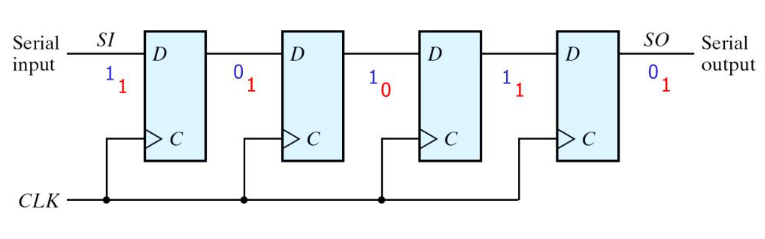
Figure 6: Counters and Shift Registers
JK flip-flops are dynamic in sequencing operations. They are widely used in counters for counting events or pulses and in shift registers for converting serial data into parallel formats. This makes them useful in managing and manipulating data across different stages of a process, such as in communication systems.
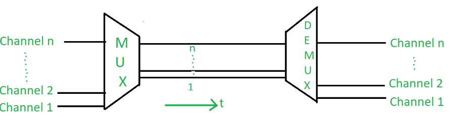
Figure 7: Frequency Division
In signal processing, JK flip-flops are often used for frequency division. By toggling their state with each clock pulse, they divide the frequency of the input signal, creating a slower, more manageable clock signal. This is noteworthy in applications like clock signal management, where timing control is desired.

Figure 8: Synchronization
JK flip-flops help synchronize multiple digital processes by ensuring that different parts of a system operate together in a coordinated manner. They ensure that various components respond correctly to timed signals, keeping the entire system in sync.
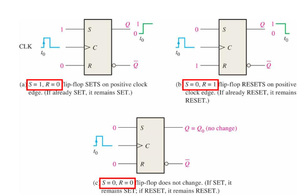
Figure 9: JK Flip-Flop: Edge-Triggered and Level-Triggered
Different Types of JK Flip-Flops
JK flip-flops are available in two main types: edge-triggered and level-triggered, each designed for different operational requirements.
Edge-triggered JK flip-flops: change their state only at specific points—when the clock signal transitions from low to high (rising edge) or high to low (falling edge). This characteristic makes them ideal for systems where precise timing is insistent. Because state changes occur exactly at the clock's edge, these flip-flops ensure all updates happen in sync with the clock pulse. This predictable behavior is dynamic in tightly controlled environments such as digital clocks, registers, and most sequential circuits. Here, the timing of each change is serious to maintaining system stability and ensuring that operations are synchronized.
Level-triggered JK flip-flops: operate differently, reacting to the input signal as long as the clock signal is at a particular level—whether high or low. They don’t wait for a specific clock transition. Instead, as long as the input meets the required conditions, the flip-flop will change states. This behavior makes level-triggered flip-flops better suited for asynchronous systems, where inputs might not align with a regular clock pulse. They provide flexibility in systems where inputs are unpredictable or arrive at irregular intervals, such as in certain signal processing tasks or monitoring systems that must react immediately to changing inputs.
Pros and Cons of JK Flip-Flop
JK flip-flops offer several benefits but also come with some trade-offs that need to be carefully weighed when designing digital systems.
|
Pros |
|
|
Versatility |
JK flip-flops are highly flexible and can
be used in various digital circuits like memory storage, counters, and
control systems. They can toggle, set, or reset based on different input
conditions, making them suitable for a wide range of applications that
require precise control over state transitions. |
|
Self-Correcting Mechanism |
One of the standout features of JK
flip-flops is their built-in feedback loop, which helps correct logical
states dynamically. This self-correction ensures that the circuit remains
stable during operation, even when inputs change rapidly. |
|
Race Condition Mitigation |
Unlike simpler flip-flops, JK flip-flops
are designed to prevent race conditions—situations where the output becomes
unstable due to conflicting input signals. This ability to maintain
consistent output, even under fast and sequential input changes, improves the
reliability of the circuit. |
|
Cons |
|
|
Complex Design |
JK flip-flops are more complicated than
basic flip-flops. Their design requires additional logic gates and input
monitoring, which can make the circuit more difficult to design and
troubleshoot, especially in systems where simplicity is preferred. |
|
Propagation Delay |
The internal gating used to manage state
transitions introduces a delay in how fast signals can be processed. In
high-speed applications, this delay can affect overall timing and slow down
the performance of the circuit. |
|
Higher Power Consumption |
Due to their complexity and the need to
constantly monitor input conditions, JK flip-flops consume more power
compared to simpler flip-flops. In larger systems or power-sensitive
applications, this higher power demand can become a drawback |
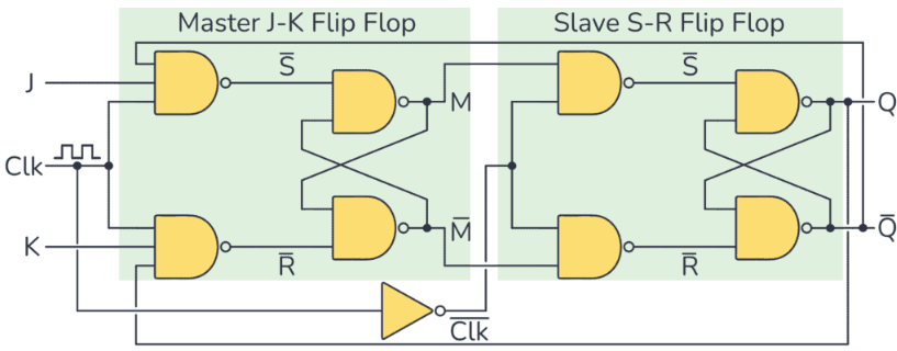
Figure 10: Master-Slave JK Flip-Flop
Decoding the Master-Slave JK Flip-Flop
The Master-Slave JK flip-flop is designed to solve the race-around condition found in standard JK flip-flops by using a two-step process to manage inputs and outputs more efficiently.
The first stage, called the master stage, captures the input values when the clock signal reaches a specific edge, either rising or falling. At this point, the input data is locked in, meaning that further changes to the inputs don’t affect the captured state until the next clock cycle. This stage ensures that the flip-flop registers the correct input without being influenced by any subsequent changes during the same clock cycle.
After the master stage is completed, the slave stage comes into play. This stage updates the output based on the data captured by the master stage, but only at the next clock edge. By separating the input capture from the output update, the slave stage ensures that the output remains stable until the master stage has fully processed the input. This prevents any premature or unintended changes in the output during the clock cycle.
Why the Master-Slave Configuration Matters?
The two-stage process stabilizes the operation of the JK flip-flop, preventing unwanted oscillations or fluctuations that can happen in simpler configurations, especially when both inputs are held high. By decoupling the input processing from the output change, the master-slave configuration ensures that outputs remain predictable and stable, even in situations where timing is valuable.
Addressing the Race Around Condition in JK Flip-Flops
Race-around conditions occur in JK flip-flops when both inputs, J and K, are high, and the clock signal remains active for too long. This leads to continuous toggling of the outputs, which can cause erratic behavior and disrupt the reliability of the circuit.
The master-slave setup uses a two-stage process to prevent race-around issues. The master stage captures the input values at the clock edge and locks them in. The slave stage updates the outputs at the next clock edge, ensuring that the output doesn't change until the inputs are fully processed. This approach effectively prevents the output from toggling uncontrollably, even if the inputs remain high for an extended period.
Another method to avoid race-around conditions is adjusting the clock pulse duration. By making the clock pulse shorter than the flip-flop’s propagation delay, you can ensure that the state doesn't change more than once within the same clock cycle. This prevents the flip-flop from toggling repeatedly during a single cycle, stabilizing the output.
Dynamics of Switching in JK Flip-Flops
The switching behavior of a JK flip-flop is largely driven by the timing of the clock signal and the input levels (J and K). The flip-flop changes state based on the inputs present at the positive edge of the clock signal. At this dangerous moment, the flip-flop evaluates the inputs and updates its output accordingly.
When the clock signal hits the rising edge, the JK flip-flop reads the current states of the J and K inputs. Depending on their values, the flip-flop will either hold, set, reset, or toggle its output.
Digital Clocks: Accuracy is everything in digital clocks, and JK flip-flops help maintain this precision by ensuring that state changes only occur at precise clock intervals.
Sequential Logic Testers: In systems that test the functionality of logic circuits, JK flip-flops play a role in verifying that each component responds correctly to specific timed signals.
Other Time-Sensitive Systems: In various digital applications where timing is risky, such as communication systems or data processing units, the JK flip-flop ensures that state transitions occur in sync with the clock, preventing timing errors.
Conclusion
The JK flip-flop stands out as an ultimate element in digital circuit design, offering a blend of versatility and precision desperate for a wide array of applications ranging from memory storage to frequency division and synchronization of digital processes. Its ability to mitigate race conditions through innovative configurations such as the Master-Slave arrangement underscores its adaptability in resolving inherent design challenges. Equally, the flip-flop's grave role in ensuring precise state transitions highlights its requisite nature in the creation and maintenance of reliable and efficient digital systems. As technology advances, the evolving designs and applications of the JK flip-flop continue to be key in pushing the boundaries of digital electronics toward more sophisticated and robust architectures.
Frequently Asked Questions [FAQ]
1. What are the applications of JK flip flop?
The JK flip-flop is used extensively in digital electronics for a variety of tasks:
Timing applications: It can serve as a delay element or a timer when connected in certain configurations.
Counters and Registers: By toggling its state with each clock pulse, it’s used in designing various counters and shift registers which are ultimate in sequential logic circuits.
Memory storage: It provides a basic unit of memory storage, useful in storing bits in computational applications.
2. How does a JK flip-flop work with a truth table?
A JK flip-flop has two inputs (J and K) and a clock signal. Its operation varies based on the input states, synchronized to the clock:
•J=0, K=0: The output doesn't change.
•J=0, K=1: The output resets to 0.
•J=1, K=0: The output is set to 1.
•J=1, K=1: The output toggles (i.e., if it was 0, it becomes 1 and vice versa).
3. What is JK flip flop and is it working?
A JK flip-flop combines the properties of SR and T flip-flops. It avoids the "forbidden" condition seen in SR flip-flops by using the JK inputs effectively:
The state of the flip-flop is controlled by the inputs J and K, which determine whether the output should hold, reset, set, or toggle, in sync with the rising or falling edge of the clock pulse.
4. What are the applications of latches and flip-flops?
Data Storage: Latches and flip-flops are serious for data storage within registers and memory arrays.
Frequency Division: Used in frequency dividers due to their ability to change states on clock edges, halving the frequency with each stage in a series.
State Machines: Basic in designing finite state machines which are used to implement sequential logic and control circuits.
Debouncing: Used to stabilize signals from mechanical switches and buttons, ensuring single, clean transitions.
5. What are flip-flops used for?
Binary Storage: Each flip-flop stores one bit of data, making them building blocks for binary storage devices.
Clock Dividers: They divide the input clock frequency by two, useful in digital clocks and timing applications.