Inclusive Guide to FM Slope Detection and Demodulation Technology
Frequency modulation (FM) serves as a cornerstone in modern communication systems, enabling the transmission of information over varying frequencies of a carrier wave. The process of demodulating an FM signal enables accurate retrieval of this information, making this task accomplished by a variety of methods, each suited to a particular application and level of complexity. Among these, the FM slope detector stands out due to its simplicity and educational value, offering a basic yet effective approach for demodulating frequency-modulated signals. This article digs into the operational principles and variations of FM slope detectors, from simple to balanced configurations, and explores their practical applications and inherent challenges. By examining the nuances of these detectors, including their circuit designs and the impact of component choices on performance, this discussion not only underscores the technological significance of FM demodulation but also highlights the ongoing advancements and adaptations in response to evolving communication needs.Catalog

Figure 1: FM Slope Detector
Basics of FM Slope Detection Technology
An FM slope detector is a basic yet effective method used to demodulate frequency-modulated (FM) signals. The process begins with a tuned circuit that is deliberately set slightly off the carrier frequency of the incoming FM signal. The key idea here is that the signal interacts with a specific part of the circuit’s response curve, known as the "slope." This interaction is desperate because changes in the frequency of the FM signal cause corresponding changes in the amplitude as the signal moves along the slope. These amplitude changes directly correspond to the frequency variations in the original FM signal.
To demodulate the signal accurately, the tuned circuit’s response must be as linear as possible, and the receiver must be finely tuned to a frequency slightly different from the carrier. The offset is intentional, allowing the signal to hit a point on the curve where the relationship between frequency and amplitude is predictable and consistent. As the FM signal varies in frequency, it will move up and down this slope, producing an amplitude-modulated (AM) signal.
While this method is conceptually straightforward, it faces practical challenges, particularly when trying to separate the desired frequency information from unwanted amplitude variations. In an ideal scenario, only the frequency changes would result in amplitude changes, but in practice, other factors can introduce unwanted amplitude fluctuations. To mitigate this issue, a limiter is often used before the signal reaches the detector. The limiter’s role is to suppress any extraneous amplitude variations that are not related to the frequency changes of interest. By doing so, the limiter ensures that the output of the slope detector more accurately represents the original frequency modulations of the signal, thus improving the overall fidelity of the demodulation process.
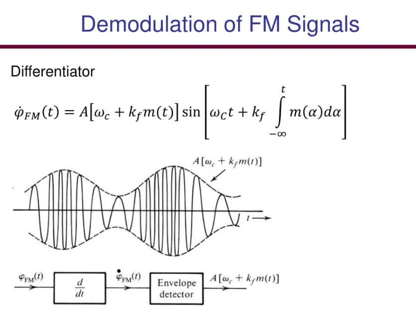
Figure 2: FM Signal Demodulation
Techniques in Demodulating FM Signals
Demodulation is basic for decoding the information carried by FM signals. In FM (Frequency Modulation), the information is embedded as changes in the frequency of the carrier wave. The main goal of an FM demodulator is to faithfully reconstruct the original signal that was encoded at the source, ensuring the received message is as clear and accurate as possible.
There are various methods for demodulating FM signals, each suited to different levels of complexity and accuracy. One of the simplest and most widely used methods is slope detection. This technique takes advantage of the natural properties of tuned circuits to translate frequency variations into changes in amplitude. In practice, as the frequency of the incoming FM signal changes, the tuned circuit produces corresponding amplitude fluctuations. These amplitude changes can then be analyzed to retrieve the original modulating frequencies.
Slope detection is an excellent starting point for anyone learning about FM demodulation because it uses basic electronic components and straightforward principles. The method serves as a practical introduction, helping to build a foundational understanding of how frequency variations can be converted into usable information. While slope detection is simple, it’s also the basis for more advanced and precise demodulation techniques. The core idea is to convert frequency shifts into voltage changes, which reflect the original signal's modulations. These more sophisticated methods build on the basic principles of slope detection, improving the accuracy and fidelity of the demodulated signal.
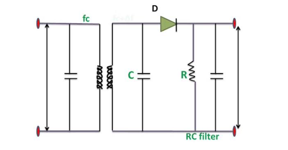
Figure 3: Simple FM Slope Detector
Designing a Simple FM Slope Detector
A simple FM slope detector, also known as a frequency discriminator, is a basic circuit used to demodulate FM signals. The operation resembles that of an AM diode detector but with a key difference: it specifically responds to changes in the frequency of the incoming signal. The core component of this setup is a tank circuit—a combination of an inductor and capacitor—designed to resonate at a particular frequency. As the frequency of the incoming FM signal shifts, the tank circuit produces an output voltage that changes accordingly.
This varying output voltage is then sent to a diode detector, which is connected to an RC (resistor-capacitor) load. The RC load is carefully calibrated to match the time constants required for the specific signal-processing tasks at hand. The diode rectifies the voltage, allowing the RC circuit to filter and smooth the signal, ultimately extracting the modulated information.
Although this method is straightforward to implement, it has several limitations. The most notable issues are related to stability and accuracy. Because the simple slope detector relies heavily on the precise tuning of the tank circuit, even minor deviations in component values or signal conditions can lead to significant errors in the demodulated output. This makes the detector more susceptible to noise, signal distortion, and other forms of interference.
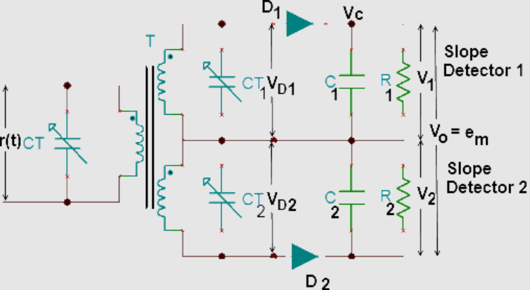
Figure 4: Balanced FM Slope Detector
Constructing a Balanced FM Slope Detector
The balanced FM slope detector, also known as a balanced frequency discriminator, is an advanced circuit designed to improve the precision and stability of FM signal demodulation. This approach builds on the basic slope detector by using two detectors working together, which enhances the accuracy of the demodulated output.
The circuit starts with a center-tapped input transformer that splits the incoming FM signal into two separate paths. These paths feed into two slope detectors, each tuned to a different frequency relative to the carrier. One detector is set slightly above the carrier frequency, and the other is tuned slightly below it. The key here is that the signals in these two paths are 180 degrees out of phase with each other, meaning that their responses to the same frequency shift will be opposite.
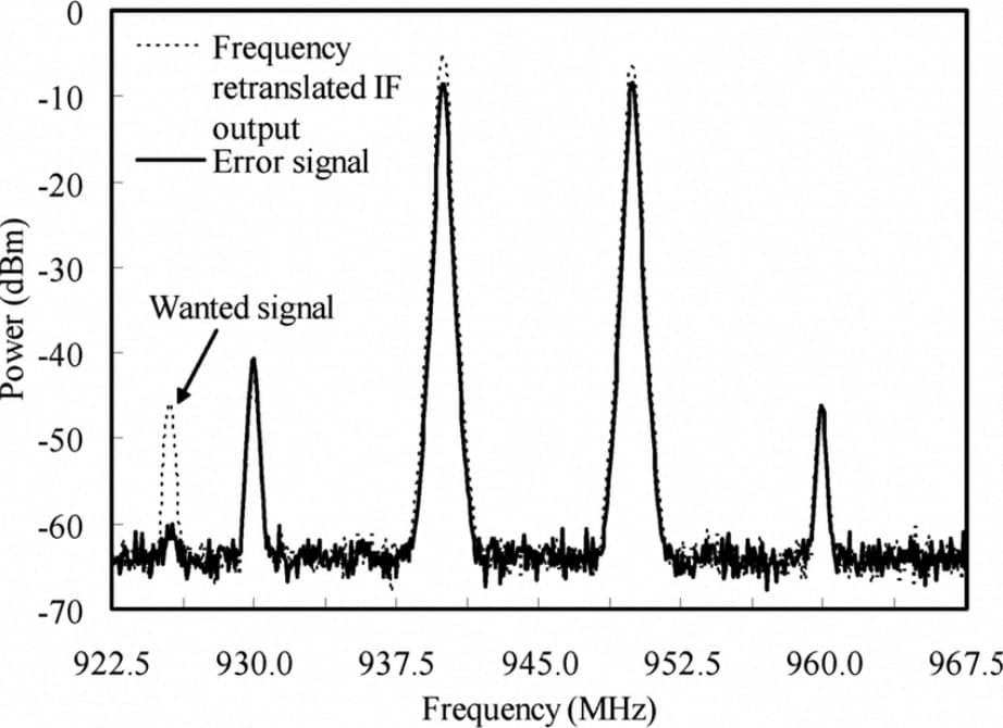
Figure 5: Signal Processing and Error Cancellation
After the two detectors process the signal, their outputs are combined by subtracting one from the other. This subtraction step is demanding—it effectively cancels out any common-mode errors, such as those caused by amplitude variations that might otherwise interfere with accurate demodulation. The subtraction enhances the linearity of the detector's response, ensuring that the output accurately reflects the original frequency shifts in the FM signal.
Different Types of FM Demodulators
Modern communication systems rely on various FM demodulators, each tailored for specific tasks and equipped with distinct operating principles. Beyond the basic slope detector, commonly used demodulators include the phase-shift detector, ratio detector, and gate-beam detector.
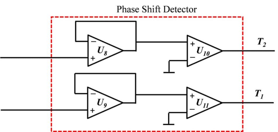
Figure 6: Phase-Shift Detector
The phase-shift detector uses a double-tuned RF transformer to detect frequency changes by observing their effect on the signal's amplitude. The transformer is carefully tuned so that any shifts in frequency result in corresponding amplitude variations, allowing for sensitive and precise demodulation.
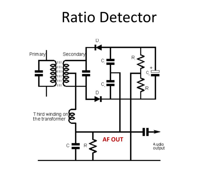
Figure 7: Ratio Detector
The ratio detector improves upon the phase-shift method by adding a third winding to the transformer. This extra winding enhances the phase shift effect, leading to more accurate and reliable frequency detection. The ratio detector is especially effective at minimizing distortions, resulting in clearer, more accurate signal demodulation.
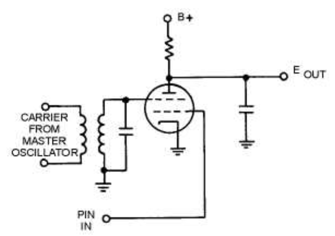
Figure 8: Gate-Beam Detector
The gate-beam detector operates by converting FM signals into AM signals using a specialized electron tube. The tube's gating action directly converts the FM signal, making this method straightforward and robust. The gate-beam detector is particularly useful in applications where a simple yet effective demodulation technique is required.
Pros and Cons of FM Slope Detection
FM slope detection is a straightforward method for demodulating FM signals. Its main appeal lies in its simplicity, as it doesn't require complex circuitry, making it an ideal choice for basic applications. This simplicity also makes it particularly useful in educational settings, where the focus is on grasping the ultimate concepts of FM signal processing.
Pos
One of the primary benefits of FM slope detection is its ease of implementation. The lack of need for additional complicated components makes it an accessible option for beginners or for situations where a quick and simple solution is required. This makes it especially valuable in experimental setups or learning environments where the goal is to understand the basics of FM demodulation without getting bogged down in technical complexities.
Cons
However, FM slope detection comes with some significant drawbacks. Its non-linear response can make it difficult to accurately reproduce the original signal, especially when precision is dangerous. In addition, the method is less effective in noisy environments, where external interference can further distort the signal, leading to errors in demodulation and signal interpretation.
Conclusion
To sum up, the FM slope detector, in its various forms, illustrates an ultimate approach to FM signal demodulation, balancing simplicity with functional depth. From the basic slope detector to the more refined balanced frequency discriminator, these devices encapsulate a range of techniques designed to convert frequency variations into discernible voltage changes, thus retrieving modulated information. Despite its limitations in precision and susceptibility to noise, the slope detection method remains a valuable educational tool and a practical choice for basic applications.
As communication technologies advance, the evolution of FM demodulators continues to adapt, striving for higher fidelity and robustness in signal processing. The exploration of these detectors not only enhances our understanding of FM demodulation but also paves the way for future innovations in the field of communication engineering.
Frequently Asked Questions [FAQ]
1. What is slope detector FM demodulation?
A slope detector for FM demodulation uses a simple tuned circuit that has its frequency response slope aligned such that it can convert frequency variations (from an FM signal) into amplitude variations. These amplitude variations are then further processed to retrieve the original audio or data signal. The slope detector exploits its selective frequency response to detect changes in the carrier frequency, which are translated into useful output signals.
2. What is FM demodulation?
FM demodulation is the process of extracting the original information, typically audio or data, from a frequency-modulated (FM) wave. This is achieved by converting the variations in the frequency of the carrier wave (used in FM transmission) back into the original signal form (like sound) that was used to modulate the frequency at the transmitter.
3. What is the purpose of a demodulator?
The primary purpose of a demodulator is to reverse the modulation process, which means converting the modulated signal back into its original baseband form (such as audio or video). This is required in communication systems to retrieve transmitted information at the receiver end.
4. What is the function of a detector?
In the context of radio and other signal reception, a detector's function is to extract the desired information from a modulated carrier wave. This involves converting the modulated signal (whether amplitude, frequency, or phase modulated) into a form that can be easily used or displayed, such as converting a radio frequency signal into an audible sound.
5. What is the main purpose of the detector?
The main purpose of a detector in communication systems is to demodulate the received signals and recover the information content that was originally encoded by the transmitter. This enables the content, whether audio, video, or data, to be presented in a usable format to the end user.