In-Depth Analysis of Shunt Voltage Regulators in Modern Electronics
This article digs into the basics of shunt voltage regulators, detailing their operation, design details, efficiency, and applications. It contrasts their performance with alternative regulatory mechanisms, explores enhancements through feedback loops and operational amplifiers, and analyzes their suitability across different applications—ranging from power management in sensitive electronic devices to renewable energy systems. Through this exploration, the article aims to provide a comprehensive understanding of the technical aspects and practical implications of employing shunt voltage regulators in modern electronic design.Catalog
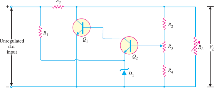
Figure 1: Shunt Voltage Regulators
Basics of Shunt Voltage Regulators
Shunt voltage regulators work by controlling the flow of current to maintain a stable voltage, regardless of fluctuations in the load. To achieve this, the regulator is connected in parallel with the load, while the load itself is in series with a resistor. This arrangement allows the regulator to respond to changes in the current draw, adjusting as desired to keep the voltage constant across the load.
In operation, the shunt regulator ensures stability by diverting current through the series resistor. When the load demands more current, the regulator reduces its intake, allowing most of the current to flow directly to the load. Conversely, when the load requires less current, or no current at all, the regulator compensates by drawing more current itself. This delicate balancing act ensures that the voltage remains stable, even if the load's current needs fluctuate.
However, this design comes with a trade-off in efficiency. The regulator continuously draws power from the voltage source, even when the load is light or disconnected. During periods of low load demand, the system wastes energy because the regulator still pulls current. This inefficiency becomes especially clear in situations where the load varies significantly or when energy conservation is a grave factor. While shunt regulators excel at maintaining stable voltage, their tendency to waste power during low load conditions makes them less ideal for applications focused on energy efficiency. In environments where energy use needs to be minimized, alternative voltage regulation methods may be more suitable.
Figure 2: Zener Diode Shunt Regulator
Exploring the Zener Diode as a Shunt Regulator
The Zener diode shunt regulator is a simple and reliable method for maintaining a stable output voltage. In this circuit, a series resistor reduces the source voltage to the desired level, allowing the Zener diode to regulate the voltage across the load. The Zener diode holds a steady voltage drop, ensuring that fluctuations in the load current don't interfere with the stability of the output voltage.
The Zener diode adjusts the current it absorbs to offset changes in the load current, keeping the output voltage consistent. This is made possible by the diode’s ability to operate in its Zener or avalanche breakdown region, where it can maintain a fixed voltage even as current levels vary. To ensure smooth and efficient performance, the Zener diode must be capable of dissipating the energy from the maximum expected current. This includes not only the peak current drawn by the load but also an additional margin to handle different operational conditions without compromising voltage stability.
A key factor in the circuit's design is the series resistor, which limits the current flowing through the Zener diode. This resistor typically contributes more to the overall circuit resistance than the power source itself. By controlling the current, the series resistor plays a major role in determining how effectively the Zener diode can regulate the voltage. Achieving reliable voltage regulation requires carefully balancing the characteristics of the Zener diode and the series resistor to meet the demands of the circuit.
Designing a Zener Diode Shunt Regulator Circuit
In this example, we'll design a voltage regulator using a Zener diode to output a stable 5.1 volts from a 12-volt source. The load will draw a small current of 2 mA. The first step is to calculate the voltage that needs to drop across the series resistor. Since the input voltage is 12 volts and the Zener diode maintains a steady 5.1 volts, the voltage drop across the resistor is 6.9 volts (12V - 5.1V). To ensure the circuit can handle varying conditions, we choose a current of 15 mA through the series resistor. This current allows for the Zener diode's minimum operating current while also providing room for slight changes in the load.
Next, we evaluate the power dissipation of the Zener diode. At a current of 15 mA and a voltage of 5.1 volts, the diode needs to dissipate approximately 76.5 milliwatts of power. This amount is well within the diode's safe operating limits, which ensures the component will perform reliably over time. Now, let's calculate the resistance value desired for the series resistor. The total current flowing through the resistor includes both the current through the Zener diode (15 mA) and the current drawn by the load (2 mA), resulting in a total of 17 mA. Using Ohm's Law (![]() ), we divide the voltage drop of 6.9 volts by the total current of 17 mA, which gives us a required resistance of about 405 ohms. Since resistors are available in standard values, we round this to the nearest value, which is 390 ohms.
), we divide the voltage drop of 6.9 volts by the total current of 17 mA, which gives us a required resistance of about 405 ohms. Since resistors are available in standard values, we round this to the nearest value, which is 390 ohms.
Finally, we need to determine the power rating for the series resistor. To do this, we calculate the power dissipation, which is the product of the voltage drop across the resistor (6.9 volts) and the current through it (17 mA). This gives us a power dissipation of around 117 milliwatts. A quarter-watt (250 milliwatts) resistor provides more than enough capacity for this design, offering a safe margin without overrating the component.
Analyzing the Efficiency of Zener Diode Shunt Regulators
Zener diode shunt regulators inherently suffer from low efficiency, primarily due to the way they manage voltage and current. A significant portion of the energy loss occurs across the series resistor, where a large voltage drop is required to keep the Zener diode operating correctly, especially when the load reaches its maximum.
In no-load conditions, the current that's meant to stabilize the output voltage ends up flowing entirely through the Zener diode. This means that even when the load is disconnected, the regulator continues to draw its full design current, wasting energy. This constant draw results in significant power loss, which is released as heat rather than being used to power a load. The issue becomes even more pronounced when the load is variable or frequently disconnected, as the system continues to consume power regardless of the actual demand.
Because of this constant current draw, Zener diode shunt regulators are generally inefficient in scenarios where energy conservation is noteworthy or where the load changes frequently. While the design is simple and works well for steady, low-power applications, it's not suited for environments that require efficiency or deal with fluctuating power needs.
Enhancing Shunt Regulators with Feedback Loops
Adding a feedback loop to a shunt voltage regulator improves its performance by allowing real-time adjustments based on continuous monitoring of the output voltage. Unlike a basic open-loop system, where the regulator operates without any feedback, this system constantly compares the actual output voltage to a set reference voltage. If any difference is detected, the feedback loop adjusts the shunt current to bring the output back to the desired level.
This feedback mechanism significantly improves the regulator's ability to respond to changes in both load and input voltage. By continuously fine-tuning the shunt current, the system maintains a stable and accurate output voltage. This is particularly valuable in scenarios where the load or input voltage fluctuates, ensuring that the regulator can keep the output voltage steady and reliable.
The feedback loop allows the shunt regulator to balance stability and efficiency dynamically. This enhanced control makes it more adaptable to varying operating conditions, ensuring that the system remains efficient while keeping the voltage precisely regulated. Such functionality is useful in serious applications where even small deviations in voltage can affect overall performance and reliability.
Shunt vs. Series Regulators
Shunt and series voltage regulators both work to keep the output voltage steady, even as input voltage or load conditions change. However, their designs and efficiency vary considerably.
Figure 3: Shunt Regulators
Shunt Regulators place their control components in parallel with the load. This setup requires a constant flow of current through the regulator, regardless of how much current the load needs. Even when the load demand is low, the regulator still draws the same amount of current, leading to higher energy consumption. This inefficiency becomes more noticeable in high-current situations, where needless power dissipation becomes a significant drawback.
Figure 4: Series Regulators
Series Regulators, on the other hand, position their control elements in series with the load. In this configuration, the regulator only draws as much current as the load requires. This design allows for better energy management because the regulator adjusts the current flow to match the load’s demands. As a result, series regulators minimize power loss when the load is low or absent, making them more efficient in applications where the load varies significantly.
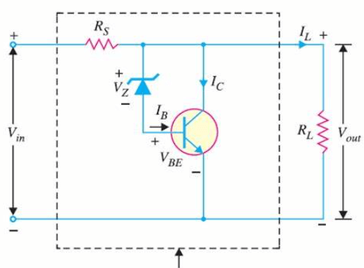
Figure 5: Transistor Shunt Voltage Regulator
The Role of Transistors in Shunt Voltage Regulation
The transistor shunt voltage regulator improves upon the basic shunt regulator by incorporating a transistor, which allows for more precise voltage control. In this design, a Zener diode is connected between the transistor's base and collector, acting as a reference point. This setup enables the transistor to adjust the current flowing through the series resistor in real-time, responding to changes in input voltage and load conditions. As a result, the regulator maintains a stable output voltage, even when input conditions fluctuate.
The transistor's inclusion makes the regulator much more responsive to varying load demands. When the Zener diode detects a change in the input or output voltage, it prompts the transistor to adjust its conductance, quickly stabilizing the voltage. This dynamic adjustment provides better control and efficiency than a simpler Zener diode-only regulator.
However, adding a transistor also increases the complexity of the circuit. Designers must carefully select a transistor that meets the voltage and current needs of the application, while also managing heat and power dissipation. This requires a solid understanding of the transistor's thermal characteristics and may involve adding extra components, like heat sinks, to ensure long-term reliability. While the advanced design offers improved performance, it demands careful attention to component selection and layout to ensure the system runs efficiently and reliably.
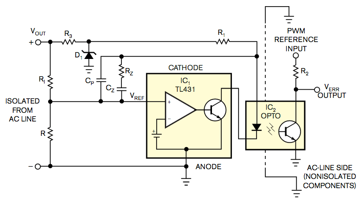
Figure 6: Shunt Voltage Regulator Using an Op-Amp
Implementing Shunt Voltage Regulation with Operational Amplifiers
A more advanced design for a shunt voltage regulator incorporates an operational amplifier (op-amp) to significantly improve voltage regulation accuracy. In this setup, the op-amp continuously compares a feedback voltage—typically obtained from precision voltage dividers—with a stable Zener diode reference. Based on this comparison, the op-amp controls the current directed to the shunt element. By adjusting the shunt current, the op-amp fine-tunes the voltage drop across the series resistor, ensuring that the output voltage remains steady, even as the load changes.
The addition of an op-amp enhances the regulator's ability to provide precise and stable voltage control. The op-amp's fast and accurate adjustments, driven by real-time feedback, make it ideal for high-performance applications where even slight voltage fluctuations can cause problems. This method not only ensures excellent voltage stability but also increases the flexibility of shunt regulators when combined with modern electronic components. This formation is especially valuable in situations where strict voltage control is useful, and the system's operating conditions may vary. The op-amp's role in this setup significantly improves the overall performance and reliability of the shunt voltage regulator.
Diverse Applications of Shunt Voltage Regulators
Shunt voltage regulators are suitable for ensuring stable and reliable power in a wide range of electronic systems.

Figure 7: Power Supply Management
Shunt regulators are commonly used in power supplies to keep output voltage stable, regardless of changes in input voltage or load. This stability is used for sensitive electronics, such as computers and communication systems, which rely on consistent power for optimal performance.

Figure 8: Battery Chargers
In battery charging systems, shunt voltage regulators help prevent overcharging by capping the charging voltage at a safe level. This is particularly noteworthy for lithium-ion batteries, where maintaining precise voltage is serious to avoid overheating or other hazardous conditions. Proper voltage regulation extends battery life and ensures safe operation.
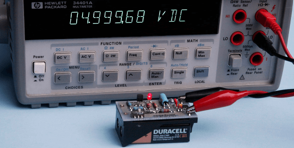
Figure 9: Voltage Reference Circuits
Shunt regulators are often used to establish stable voltage references in circuits. These references are dynamic for ensuring accuracy in analog-to-digital converters, sensor interfaces, and other precision applications where consistent measurements are required.
Figure 10: Overvoltage Protection
Shunt regulators act as protective devices by clamping excess voltage and preventing damage to electronic components. During power surges or spikes, they absorb the extra voltage, shielding downstream devices from overvoltage damage.

Figure 11: Electrostatic Discharge (ESD) Protection
In environments prone to electrostatic discharge, such as manufacturing floors or repair facilities, shunt regulators help protect sensitive components. By neutralizing sudden voltage spikes caused by ESD, they prevent costly damage to delicate microelectronics.

Figure 12: Renewable Energy Systems
In solar power and other renewable energy systems, shunt regulators stabilize the voltage going into storage batteries or converting it to usable power. They ensure efficient energy conversion and prevent energy loss, optimizing the system's overall performance.

Figure 13: Automotive Electronics
In vehicles, shunt regulators manage the voltage supplied to various onboard electronics, such as sensors and infotainment systems. By keeping the voltage steady, they help improve vehicle performance and ensure the reliability of serious systems.
Pros and Cons of Using Shunt Voltage Regulators in Electronic Circuits
Shunt voltage regulators are widely used for their simplicity and low cost, making them a common choice in less complex applications. However, their advantages and disadvantages depend heavily on the specific requirements of the system.
Pros
Simple and Cost-Effective Design: Shunt regulators have a straightforward design with fewer components, which lowers production costs and makes them easier to implement. This simplicity often improves reliability, especially in basic applications where advanced regulation isn’t needed.
Fast Response to Voltage Changes: One of the key benefits of shunt regulators is their ability to quickly adjust to fluctuations in input voltage. This ensures the output voltage remains stable, even when the load varies, making them useful in systems where voltage stability is used but the demands are not too high.
Reliable in Non-Serious Systems: For applications where extreme precision isn’t required, shunt regulators provide a reliable solution without the added cost or complexity of more advanced regulators. They are ideal for straightforward, low-power circuits.
Cons
Low Efficiency: Shunt regulators work by diverting excess voltage to the ground, which causes constant power loss. This leads to poor efficiency, especially in systems where energy conservation is substantial. The constant energy dissipation occurs even when there is little or no load, making them less ideal for energy-sensitive applications.
Heat Management Issues: Due to continuous power dissipation, shunt regulators generate heat, particularly in higher-power applications. Managing this heat often requires additional components like heat sinks, which adds complexity and increases costs. This thermal issue can become a significant design challenge when handling larger loads.
Limited Power Handling: Shunt regulators rely on components such as Zener diodes and transistors, which may not be able to handle high currents. These components can fail under heavy loads, limiting their use in high-power applications and raising concerns about reliability in demanding environments.
Best for Low-Power Applications: Given these limitations, shunt voltage regulators are generally better suited for low-power applications. They are less effective in high-power systems due to their inefficiency and limited ability to handle large currents.
Conclusion
Shunt voltage regulators, with their ability to provide quick voltage stabilization, represent a simple yet effective solution for a variety of electronic applications. However, the inherent inefficiencies, particularly under low-load conditions or in energy-sensitive environments, highlight the limitations of traditional shunt designs. Advanced configurations using feedback mechanisms, transistors, and operational amplifiers offer significant improvements in performance, precision, and energy efficiency.
These enhancements make shunt regulators versatile enough to meet the stringent requirements of modern electronic systems, including automotive electronics, renewable energy systems, and sensitive data transmission networks. Despite their drawbacks, such as heat generation and limited high-power capabilities, the evolution of shunt voltage regulator technology continues to expand their applicability. The detailed examination of these regulators, from basic designs to sophisticated systems, underscores the importance of choosing the right voltage regulation method to match specific application needs, ensuring both reliability and efficiency in electronic circuit design.
Frequently Asked Questions [FAQ]
1. What is a shunt voltage regulator?
A shunt voltage regulator is a device used to maintain a constant voltage level. It works by providing a path from the supply voltage to the ground through a regulating element. This element continuously adjusts its resistance to shunt the varying amounts of current away from the load to stabilize the output voltage.
2. Is a Zener diode a shunt regulator or a voltage regulator?
A Zener diode functions as a shunt voltage regulator. It is specifically designed to operate in its reverse breakdown region. When the voltage across the Zener diode exceeds a certain threshold, known as the Zener voltage, it conducts current from the supply to the ground, thereby stabilizing the voltage across the load to its breakdown voltage.
3. What is the purpose of a shunt?
In electrical and electronic systems, a shunt is used to create a low-resistance path for current to flow. This can be for purposes such as diverting current, measuring current flow by creating a voltage drop that can be easily measured, or regulating voltage as in the case of shunt regulators.
4. What is the advantage of using a shunt?
Shunts offer a simple and cost-effective way to manage and control electrical characteristics in a circuit. For example, in voltage regulation, shunts like Zener diodes provide a straightforward approach to maintaining a steady voltage. In measurement, shunts allow for accurate current monitoring without significant disruption to the overall circuit.
5. What are the two types of shunts?
Measurement Shunts: Used primarily for measuring current, these shunts are precision resistors placed in series with a load. The voltage drop across them, proportional to the current, is measured and used to calculate the actual current flowing through the circuit.
Regulating Shunts: These include devices like Zener diodes that are used in voltage regulation circuits. They help maintain a constant voltage by shunting excess current when the voltage exceeds a predetermined level.