How to Test a Transistor and a Diode with a Multimeter?
Testing electronic parts like diodes and transistors is important to make sure electronic devices and circuits work properly. Diodes control the direction of current, and transistors amplify signals and switching functions. Careful testing ensures circuits stay reliable. This article explains how to use both analog and digital multimeters to test these components, emphasizing the need to understand their features and functions before testing. Since diodes allow current to flow in only one direction and transistors control current flow in a circuit, it's important to check if they are working correctly. We provide step-by-step instructions for testing diodes in different modes with digital multimeters and offer a detailed guide for testing both NPN and PNP transistors, helping to diagnose and maintain their electronic parts.Catalog
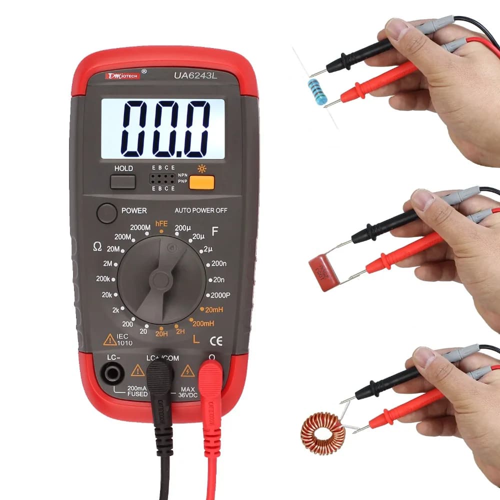
Figure 1: Testing Electronic Parts with Multimeter
How to Test a Diode?
A diode is an important part of many electronic circuits because it only lets current flow in one direction. This makes it useful in devices like rectifiers, clampers, and clippers. To test a diode properly, it's helpful to first understand how it works. A diode has two ends: the anode and the cathode. When the anode is connected to a positive charge compared to the cathode, the diode is "forward-biased," allowing current to pass through. For silicon diodes, this usually happens at about 0.7V, which is the point where the diode starts to conduct electricity.
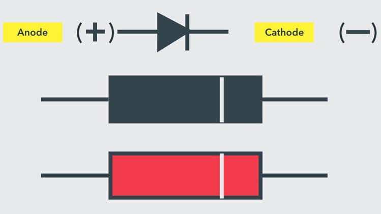
Figure 2: Diode Symbol and Terminals
Identifying the ends of a diode is easy. Most diodes have a white band around the cathode. The part next to this band is the cathode, and the other end is the anode. This marking is common for different types of diodes, though the colors might be different, like zener diodes which might have a black mark on a red or orange body. Once you've found the anode and cathode, testing a diode is simple and can help you check if it's working correctly. Understanding these basics and testing your diode properly are required keeping your electronic circuits running smoothly.
How to Test a Diode with a Digital Multimeter?
You can test a diode using a Digital Multimeter (DMM) in two main modes: Diode Mode and Resistance (Ohmmeter) Mode. Diode mode is the best option for this because it checks the diode's behavior by measuring the voltage drop across it when it's forward biased. A working diode will show a voltage drop, indicating that current can flow through it. In contrast, resistance mode involves measuring the resistance of the diode in both forward and reverse biases. A functioning diode will show low resistance (from a few hundred ohms to a few kiloohms) in forward bias and very high resistance, displayed as OL (open loop), in reverse bias.
Figure 3: Diode with a Digital Multimeter
Diode Mode Testing Procedure
• Identify the anode and cathode of the diode.
• Set your DMM to Diode Mode, marked with a diode symbol. This mode passes a small current (around 2mA) through the diode.
• Connect the red probe to the anode and the black probe to the cathode, placing the diode in a forward-biased state.
• Check the multimeter display. A healthy silicon diode will show a voltage drop between 0.6 and 0.7 volts while a germanium diode will show between 0.25 and 0.3 volts.
• Reverse the probes to put the diode in reverse bias. The multimeter should display OL or 1, indicating no current flow, means the diode is working properly.
• If the readings differ from these expectations, the diode may be defective, either open (no current flows in both directions) or shorted (current flows in both directions with little to no voltage drop).
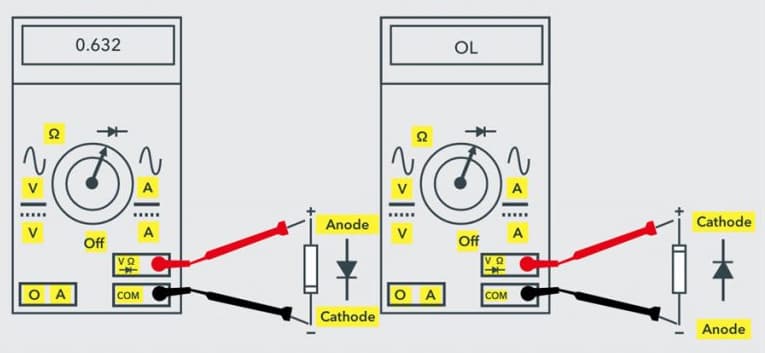
Figure 4: Testing a Diode using Diode Mode in Digital Multimeter
Ohmmeter (Resistance) Mode Testing Procedure
• Start by identifying the anode and cathode.
• Set your DMM to Resistance Mode, choosing a low resistance range for forward bias and a high range for reverse bias.
• Connect the red probe to the anode and the black probe to the cathode to forward bias the diode. A low resistance reading suggests the diode might be faulty, while readings between several hundred ohms and a few kiloohms indicate it is functioning correctly.
• Reverse the probes for reverse bias testing. The multimeter should show high resistance or OL, confirming the diode is working as expected.
• The diode is considered open if it shows high resistance or OL in both directions, and shorted if low resistance readings are observed in both directions.
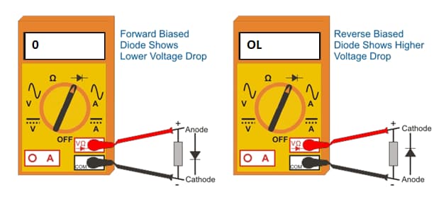
Figure 5: Testing a Diode using Ohmmeter in Digital Multimeter
How to Test a Diode with an Analog Multimeter?
Most analog multimeters don't have a special mode just for testing diodes, so we use the resistance mode, similar to how we test a diode with a digital multimeter.
• Start by setting the multimeter to a low resistance setting.
• Connect the multimeter's positive lead to the diode's anode (the positive side) and the negative lead to the cathode (the negative side). This is called forward biasing the diode.
• If the multimeter shows a low resistance value in forward bias, the diode is working properly.
• Now, set the multimeter to a high resistance setting and switch the connections—connect the positive lead to the cathode and the negative lead to the anode. This is the reverse bias condition.
• If the multimeter shows "OL" (overload) or a very high resistance in reverse bias, the diode is in good condition.
• If the multimeter doesn't show the expected readings in either forward or reverse bias, the diode is probably faulty or damaged.
This is a simple method for testing basic PN diodes with both digital and analog multimeters. However, other types of diodes, like LEDs and Zener diodes, may need different testing methods.
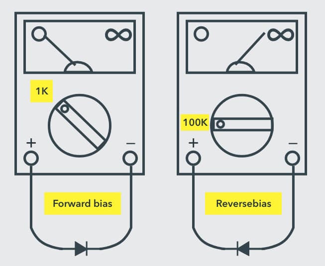
Figure 6: Testing a Diode using Analog Multimeter
How to Test a Transistor with a Multimeter?
To get started, you'll need a few basic tools: a multimeter (either analog or digital) with a transistor testing or diode test feature, and a variety of transistors, both NPN and PNP types, for practice. Before testing, it's important to understand the basics of a transistor's structure. In an NPN transistor, the collector and emitter are negative, and the base is positive. In a PNP transistor, the collector and emitter are positive, and the base is negative.
Testing Procedure for NPN Transistors
First, set your digital multimeter to the diode testing mode. This mode helps you measure the voltage drop across the transistor’s junctions.
• Turn on the multimeter and choose the diode test mode (look for a diode symbol).
• Connect the red lead to the positive terminal and the black lead to the negative terminal.
Next, check if the base-emitter junction of the transistor is working.
• Connect the red lead to the base (B) of the transistor.
• Connect the black lead to the emitter (E).
• Check the reading on the multimeter.
A good NPN transistor will show a voltage drop between 0.45V and 0.9V. If the reading is outside this range, the transistor might be faulty.
Now, check the base-collector junction to see if it’s working correctly.
• Keep the red lead on the base (B).
• Move the black lead to the collector (C).
• Check the multimeter reading.
Like the base-emitter test, the voltage drop should be between 0.45V and 0.9V. Anything different might mean the transistor is damaged.
Next, test the transistor in reverse bias to make sure no current flows.
• Switch the red lead to the emitter (E) and the black lead to the base (B). Check the reading.
• Switch the red lead to the collector (C) and the black lead to the base (B). Check the reading.
In both tests, the multimeter should show "OL" (Over Limit) or no continuity. If there’s a voltage drop, the transistor might be faulty.
After running these tests, you should be able to tell if the NPN transistor is working correctly. A good transistor will show a forward voltage drop between 0.45V and 0.9V across both the base-emitter and base-collector junctions and will show "OL" or no continuity when these junctions are reverse-biased. For accurate results, test the transistor outside the circuit and handle it carefully to avoid damage. If you're unsure about the results, you can compare your readings with those of a known good transistor of the same type.
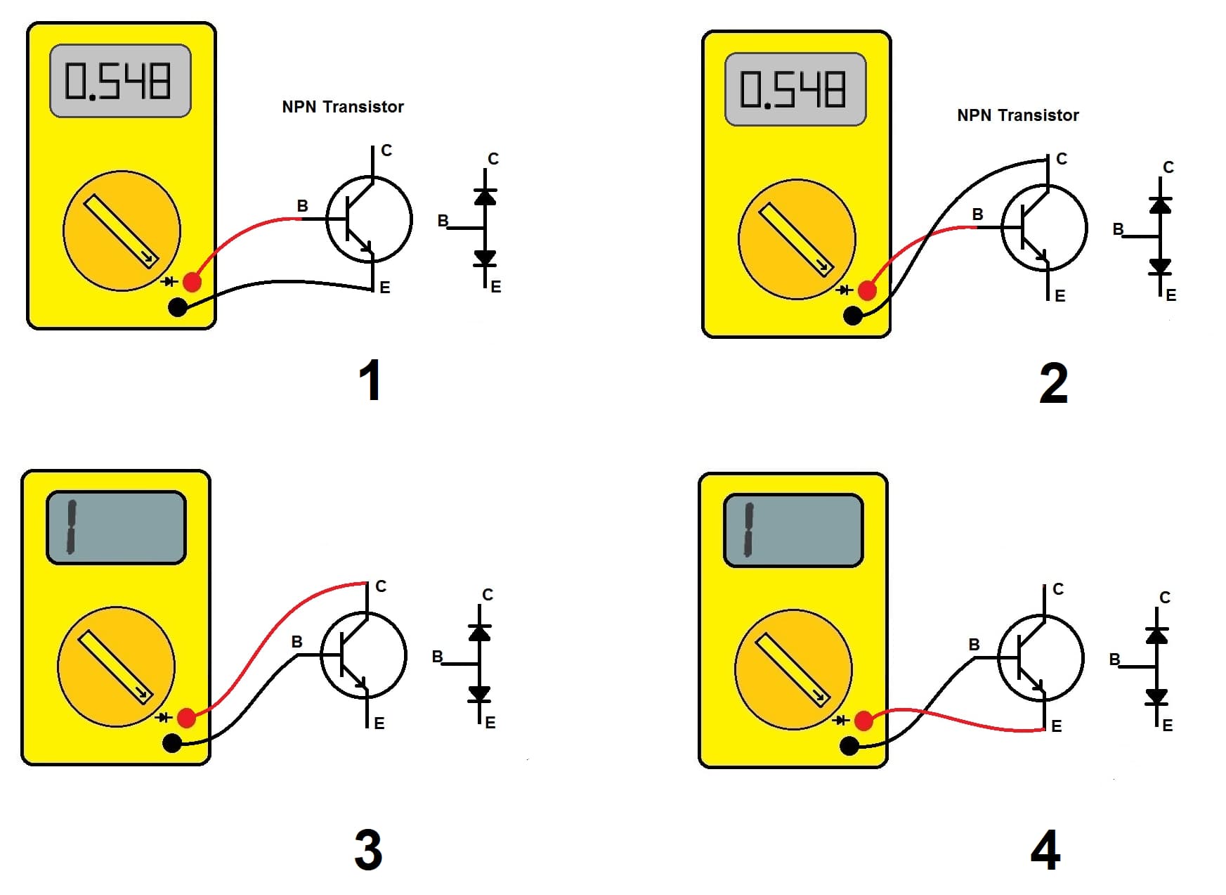
Figure 7: Using Multimeter with NPN Transistor
Testing Procedure for PNP Transistors
Before you start, make sure the transistor is not connected to any circuit. Set your multimeter to the diode test mode (look for a diode symbol on the device). This setting helps you measure the voltage drop across the transistor’s parts.
• Connect the black (negative) lead to the base (B) of the transistor.
• Connect the red (positive) lead to the emitter (E).
• Look at the reading on the multimeter.
The multimeter should show "OL" (Over Limit) or no voltage drop. This means the base-emitter junction is reverse-biased, as it should be in a working PNP transistor.
• Keep the black lead on the base and move the red lead to the collector (C).
The multimeter should again show "OL," confirming the base-collector junction is also reverse-biased.
• Switch the leads: connect the red (positive) lead to the base and the black (negative) lead to the emitter.
The multimeter should show a voltage drop between 0.45V and 0.9V, indicating a healthy forward-biased junction.
• With the red lead still on the base, move the black lead to the collector.
A similar voltage drop (0.45V to 0.9V) should appear, showing that the collector-base junction is forward-biased and working correctly.
• No matter how you connect the leads (red to collector and black to emitter, or vice versa), the multimeter should show "OL."
There should be no direct connection between the collector and emitter in either direction. If you see continuity or low resistance, the transistor might have a short circuit and could be faulty.
To analyze the results of a transistor test, a good PNP transistor will exhibit the expected voltage drops across the base-emitter and base-collector junctions when forward-biased, and display "OL" (open loop) when reverse-biased or when testing for continuity between the collector and emitter. And if the readings deviate from these expectations, such as showing continuity where it shouldn't or an unusual voltage drop, this indicates that the transistor might be damaged or defective.
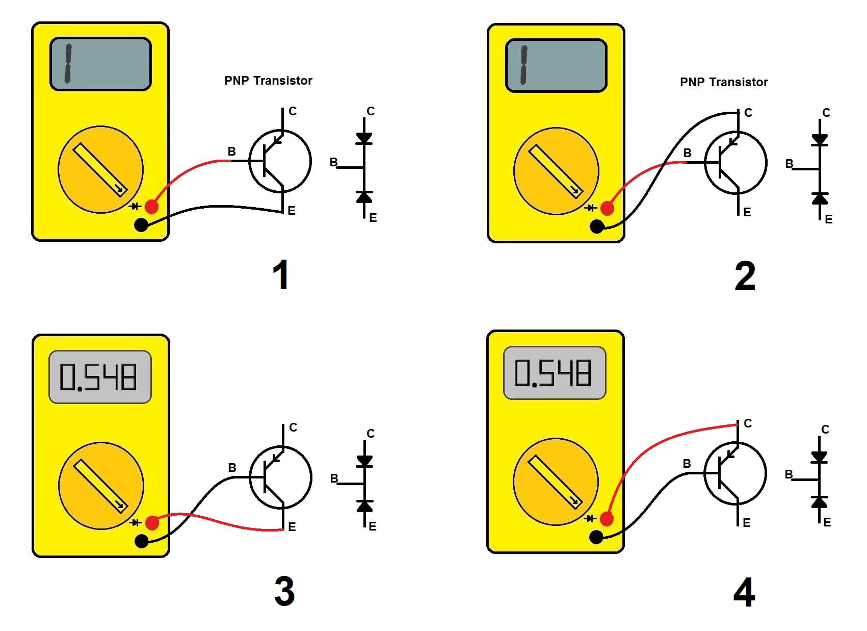
Figure 8: Using Multimeter with PNP Transistor
Conclusion
Knowing how to test diodes and transistors with a multimeter is a valuable skill for anyone working with electronic circuits. This article has explained step-by-step methods for checking these components, which is important to prevent circuit problems and improve the performance of electronic devices. By using diode and resistance modes for diodes, and following specific steps to test NPN and PNP transistors, you can spot common issues like open circuits or shorted connections. Understanding the expected voltage drops and resistance values is also useful to troubleshooting and making sure components work well. Following these testing methods, you can make sure your electronic parts work properly, and helps improve the reliability and efficiency of your electronic projects.
Frequently Asked Questions [FAQ]
1. How do you check if a transistor is NPN or not?
To find out if a transistor is NPN, set your digital multimeter to the diode check function. Connect the black lead to one terminal and the red lead to another. You're looking for a voltage drop between 0.5V to 0.7V when the black lead is on the emitter and the red lead is on the base. This drop indicates an NPN transistor. Reverse the leads on each pair of terminals until you consistently get this reading when the black lead touches the emitter. Accuracy in placing the leads and observing the voltage reading is required, as this specific setup should only work for an NPN transistor.
2. How do you identify transistor terminals with a multimeter?
To identify the base, collector, and emitter of a transistor using a multimeter set to diode mode, start by testing each pair of terminals. Place the red lead on one terminal and the black lead on another, and record the voltage reading. Do this for all three possible pairs. The base will conduct with both the emitter and collector but will show different readings. The emitter-base junction has a higher forward voltage than the collector-base junction. The terminal with the higher voltage drop when connected to the base is the emitter. This process requires careful and consistent readings to accurately identify each terminal.
3. What are two methods of testing a transistor?
Multimeter Diode Test: Set the multimeter to diode mode and check each junction, base-emitter and base-collector, for a forward voltage drop. Make sure there's no conductivity when you reverse the leads, confirming that the transistor isn't shorted or open.
Gain Check (hFE Mode): Set the multimeter to hFE mode and place the transistor in the appropriate socket. The multimeter will display the gain value, shows the transistor's amplification ability. Both methods require systematic switching between terminals and careful observation to detect any functional issues with the transistor.
4. What is the meaning of hFE in multimeter?
hFE on a multimeter refers to hybrid parameter forward current gain, also known as beta (β). It measures the DC gain of a transistor, indicating how many times the base current is amplified in the collector current. A higher hFE value means better current amplification, which is important when transistors are used as amplifiers.
5. What does 200m mean on a multimeter?
The "200m" setting on a multimeter is the maximum range for measuring currents up to 200 milliamperes (mA). This setting is important for accurately measuring low currents, ensuring that the multimeter can measure small currents precisely without overloading. It's useful for diagnosing low-current devices.