How Do Multiple-input Gates Work?
In the expanding field of digital electronics, logic gates form the backbone of computational processes, enabling the execution of logical operations that are core to modern technology. These gates, varying from simple NOT gates to complex Exclusive-OR (XOR) and Exclusive-NOR (XNOR) gates, serve as the dangerous building blocks for intricate digital circuits. By harnessing different types of technology, such as Transistor-Transistor Logic (TTL) and Complementary Metal-Oxide-Semiconductor (CMOS), these gates can be tailored to meet specific power, speed, and efficiency requirements. This article investigates deep into the operational mechanics, applications, and types of various digital logic gates, providing a basic understanding of their role in electronics. It explores the principal distinctions between TTL and CMOS technologies, the versatility of gates like NAND and NOR in constructing complex logical functions, and the nuanced operations of XOR and XNOR gates in advanced computational circuits. This complete exploration underscores the importance of logic gates in shaping the functionality and efficiency of modern digital systems.Catalog
Digital Logic Gates
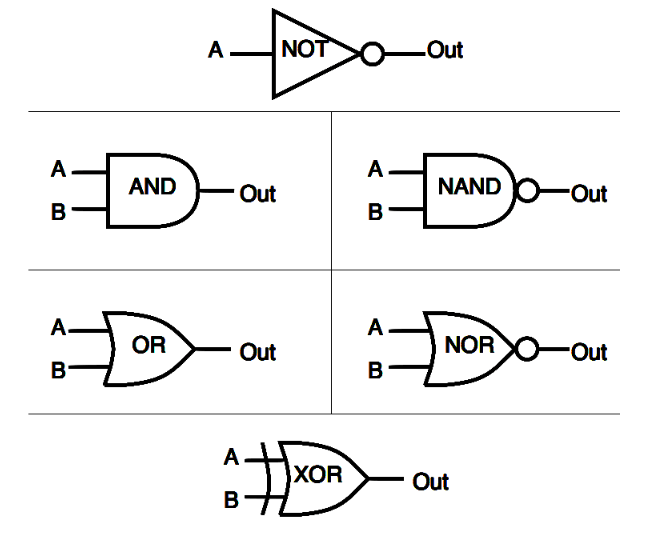
Figure 1: Digital Logic Gates
Digital logic gates are basic components in electronics, used to perform logical operations based on digital signal states. Each gate typically has several inputs (labeled A, B, C, D) and one output (Q). By connecting these gates, we can create circuits that range from simple combinational systems to complex sequential setups, enabling advanced logical functions using basic gates.
The most common types of gates are Transistor-Transistor Logic (TTL) and Complementary Metal-Oxide-Silicon (CMOS). TTL gates use Bipolar Junction Transistors (BJTs), including both NPN and PNP types, which allow for fast switching and high drive capabilities. In contrast, CMOS technology uses pairs of MOSFETs or JFETs in complementary arrangements, significantly reducing power consumption due to minimal current draw when in a static state. This difference highlights the distinct methods of digital signal processing in different gate families.
The choice between TTL and CMOS can significantly affect circuit design due to their different electrical characteristics. TTL gates switch faster, making them ideal for dangerous applications, but they consume more power and generate more heat. To manage this, operators often need to use cooling systems or heat sinks to maintain performance.
On the other hand, CMOS gates are preferred in battery-operated or energy-sensitive applications because they consume less power. They draw minimal power in a static state and only dissipate power during switching events. This requires precise timing and control to optimize power efficiency and minimize heat during rapid switching.
What Is NOT Gate?
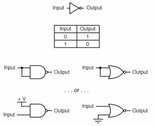
Figure 2: Circuit Diagram for Not Gate
The NOT gate, also called an inverter, is a core digital logic gate that takes one input and outputs its opposite. If the input is high (true), the output will be low (false), and if the input is low, the output will be high. This simplicity makes the NOT gate an ideal starting point for learning about digital logic.
Operators might see different symbols and representations of NOT gates depending on regional and international standards. This variability highlights the gate's widespread use and principal importance in digital design. Despite its simplicity, the NOT gate is needed in more complex operations, such as creating toggle conditions in flip-flops or controlling timing elements in synchronous circuits.
Common Applications of NOT Gate
Its most straightforward application is the logic signal inversion, basic in digital circuits where a certain logic operation requires the opposite logic state. NOT gates generate complementary signals in systems, especially needed in memory and processing circuits. By combining a NOT gate with components like capacitors and resistors, simple oscillators can be created, generating a continuous square wave signal used in timing and control applications. In control logic circuits, NOT gates ensure specific conditions are met before initiating an action, such as disabling a part of a circuit unless all safety conditions are satisfied. They are also instrumental in complex digital circuits alongside other logic gates, such as AND and OR gates, to build sophisticated functions for devices like multiplexers, decoders, and arithmetic logic units. NOT gates play a role in debouncing circuits that stabilize signals from mechanical switches and buttons to prevent false triggering. They are also used in signal conditioning to maintain signal integrity, and safeguard signals are read correctly by digital inputs.
What Is AND Gate?
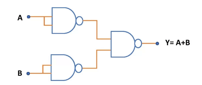
Figure 3: Nand Gate Circuit Diagram
The AND gate is a core component in digital electronics, performing a logical conjunction similar to arithmetic multiplication. It produces a high output only when all its inputs are high, typically represented by a dot (.) in schematics. This gate is needed in applications ranging from basic arithmetic circuits like adders to complex systems such as traffic control and security applications.
It is required for precise control operations. In arithmetic circuits like adders and multipliers, the AND gate synchronizes multiple signals to ensure accurate calculations. In traffic management systems, AND gates coordinate signals to ensure traffic flow changes occur only under safe conditions.
Two Types of AND Gates
• 3-input AND gate - It is a digital logic gate that outputs a high signal only if all three of its inputs are high, functioning based on the logical "AND" operation principal in digital electronics. Its symbol includes three lines entering a single gate, symbolizing that all inputs must be true for the output to be true. This type of gate is utilized in various applications, such as decision-making circuits where it controls mechanisms that activate only when three separate conditions are detected by sensors. It's needed in safety systems, to ensure machinery operates only under safe conditions, such as a press functioning only when safety guards are in place, the operator is at a safe distance, and the correct operational mode is selected. 3-input AND gates are ideal for electronic combination locks, requiring three correct inputs to unlock a mechanism. In complex control systems found in robotics or automated production lines, these gates ensure actions proceed only when multiple preconditions are met, including positional data and system readiness.
• 2-input Transistor AND Gate - A basic 2-input transistor AND gate can be constructed using resistor-transistor logic (RTL), which requires both transistors to be active (on) for the output to be high. This setup is particularly useful for understanding electronic signal flow and the needed conditions to achieve the desired output. AND gates are needed in real-world systems, such as traffic light control where they ensure that lights change only when multiple safety conditions are met, thus preventing accidents. In security systems, AND gates coordinate responses to multiple sensor inputs, guaranteeing that alarms trigger only under specific conditions. The AND gate is required in digital systems, managing synchronized inputs to produce accurate outputs. Its applications extend from simple arithmetic operations to dangerous roles in traffic and security systems, where precise conditional responses are basic.
What Is NAND Gate?
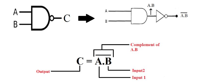
Figure 4: Nand Logic Gate Circuit Diagram
The NAND gate is the logical inverse of the AND gate. It outputs a low signal only when all inputs are high; otherwise, it outputs high. The design and operation of the NAND gate are core, especially when using CMOS technology where the configuration of n-type and p-type transistors allows for efficient switching and minimal power leakage, basic for battery-operated devices. The gate's ability to maintain a high output under most conditions helps conserve power, making it invaluable in energy-sensitive applications.
NAND gates are extremely versatile, used in everything from basic security systems, where they can trigger alarms only under specific conditions, thus elevating reliability and reducing false alarms, to complex computational logic. They are foundational in constructing other basic gates like AND, OR, and NOT through various combinations, underscoring their dangerous role in digital circuit design. Beyond simple gates, NAND gates are instrumental in creating more complex logic circuits and sequential devices, playing a key role in memory storage and retrieval in computational devices, which demonstrates their broad utility in modern electronics.
Different Types of NAND Gate
• Basic NAND Gate - A basic NAND gate is the most common type of digital logic gate, and it performs the logical complement of the AND gate's function. It has two or more inputs and one output. In essence, a NAND gate will output a high signal (1) unless all its inputs are high (1), in which case it outputs a low signal (0). This gate is represented symbolically by an AND gate with an inversion circle at the output, denoting the NOT operation applied to the AND gate's result.
• Multi-input NAND Gate - This gate extends the basic NAND gate concept to three or more inputs. Like its simpler counterpart, the output of a multi-input NAND gate is low only if all its inputs are high. The increase in the number of inputs allows for more complex logic functions and integrations in circuits, reducing the need for multiple two-input gates in series or parallel configurations.
• Schmitt Trigger NAND Gate - A gate incorporates a Schmitt Trigger mechanism, which adds hysteresis to the input-output transition. This means the voltage thresholds for switching from high to low and low to high are different. Such gates are particularly useful in environments with noisy signals where the input might fluctuate, as the hysteresis helps to stabilize the output by reducing false transitions.
• CMOS NAND Gate - These gates are made from pairs of p-type and n-type MOSFETs arranged to perform the NAND function. CMOS technology is prized for its low power consumption and high noise immunity, making it ideal for battery-operated devices and large-scale integration in microprocessors and other digital ICs.
• TL NAND Gate - TTL (Transistor-Transistor Logic) NAND gates utilize bipolar junction transistors (BJTs) and resistors. Although they generally consume more power and are less noise-immune compared to CMOS gates, TTL NAND gates are faster, which is needed in applications where speed is a dangerous parameter.
• Open Collector NAND Gate - Open collector NAND gates feature a unique output stage where the output transistor only pulls the line low (active low). An external resistor must pull the line high when the output transistor is off. This configuration is used in situations where several devices need to share a single output line, commonly seen in buses or other multi-device communication setups.
Logic OR Gate
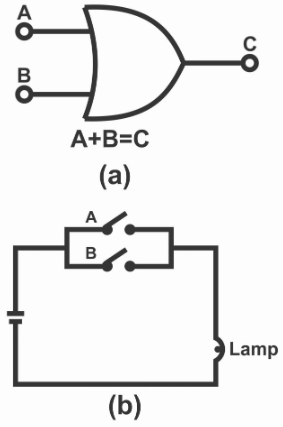
Figure 5: Logic OR Gate Diagram
The OR gate is a basic digital logic component that outputs a high signal if any of its inputs are high. This function is suitable for circuits that need to respond positively to any high signal.
This type of gate is basic in scenarios requiring decisions based on multiple input conditions. For instance, in automated systems, an OR gate might control actuator responses to various sensor inputs, confirming that action is taken if any condition is met. Operators need to understand the shades of the OR gate's behavior, especially its ability to rapidly process and respond to changing inputs, a feature that is needed in dynamic environments. This sensitivity is particularly required in safety systems, where quick detection of any hazardous condition must trigger an immediate preventive response.
Uses of Logic OR Gate
The Logic OR gate is widely utilized in alarm systems and can initiate an alert if any one of several sensors detects a breach. It is also basic in control systems, where it can ensure that a machine operates if any of the needed conditions are met, such as safety checks or readiness signals. OR gates are used in complex computational logic, aiding in the execution of algorithms that require at least one of several inputs to be true to proceed. Their ability to handle multiple conditions simultaneously makes them core in both simple and complex digital systems, streamlining operations and elevating system responsiveness.
What Is NOR Gate?
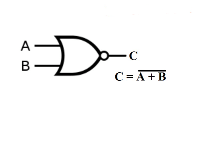
Figure 6: NOR Gate
The NOR gate is a key component in digital electronics, outputting a high signal only when all its inputs are low. This makes it the logical inverse of an OR gate and is basic in digital circuit design for universally negating inputs.
It is particularly valuable due to its exclusive high output under low input conditions, which allows for tight control in digital systems. For example, in an access control system, a NOR gate ensures that entry is permitted only when all specific safety and security conditions are unmet, effectively preventing unauthorized access. Operators of such systems must skillfully manage the NOR gate's response dynamics, especially in complex circuits where multiple NOR gates interact. This management often requires careful timing and synchronization to achieve the desired outcomes, which is needed for creating fail-safe mechanisms and conditional response systems.
Its ability to provide a high output allows for the construction of complex logic functions with fewer components by combining NOR gates, thereby reducing the overall complexity and cost of the circuit. NOR gates are principal in building other types of logic gates and digital circuits, such as inverters, OR gates, and even more complex configurations, elevating design flexibility. Their use of in-memory storage circuits, like latches, further underscores their versatility and efficiency.
Exclusive-OR Gate
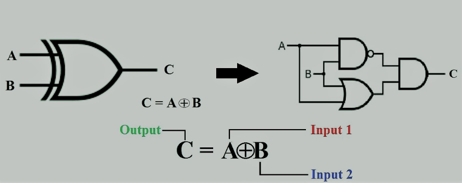
Figure 7: Exclusive-OR Gate
The Exclusive-OR (Ex-OR) gate is required in computational circuits, performing arithmetic functions and safeguarding data integrity through error detection. Its ability to distinguish between different input states makes it required for precise logical operations in digital systems.
The Ex-OR gate is core for tasks such as binary addition and conducting parity checks. In the context of binary addition, the Ex-OR gate is tasked with calculating the sum of two bits, while a separate mechanism manages the carry-over. This functionality is required for supporting more complex arithmetic operations within computational architectures. Technicians working with Ex-OR gates need to thoroughly understand their unique input response characteristics—the gate produces a high output only when the inputs differ. Properly setting up and troubleshooting Ex-OR gates involves guaranteeing precise signal timing and alignment, which is particularly needed in sequential logic circuits where the order of operations can affect the outcome.
Different Types of Exclusive-OR Gate
• Basic Two-Input XOR Gate - The basic two-input XOR gate is represented by a standard logic symbol featuring a curved line on the input side. It outputs true when the inputs differ from each other, such as in the cases of 01 or 10. The Boolean expression for this XOR operation is represented as or , which encapsulates the exclusive nature of the gate, where only differing input combinations result in a true output.
• Multiple-Input XOR Gate - The logic symbol for a multiple-input XOR gate is an extension of the basic XOR gate, accommodating more input lines. Its truth table is designed to output true for an odd number of true inputs, reflecting its parity logic functionality. Typically, multiple-input XOR gates are realized by cascading two-input XOR gates to handle several inputs efficiently.
• CMOS XOR Gate - CMOS XOR gates utilize complementary metal-oxide-semiconductor technology, which includes both NMOS and PMOS transistors. This technology is celebrated for its low power consumption and high input impedance, making it particularly suitable for battery-operated devices. The configuration of CMOS XOR gates usually involves a more intricate arrangement of transistors than those found in TTL circuits.
• TTL XOR Gate - TTL XOR gates are constructed using transistor-transistor logic, which relies heavily on bipolar junction transistors. These gates are known for their rapid operation and noise tolerance, qualities that make them apt for industrial environments. The typical configuration includes multiple transistors and may also incorporate diodes to effectively realize the XOR function.
• Optical XOR Gate - Optical XOR gates operate with light signals instead of electrical ones. They are based on principles like interferometry or nonlinear optical effects. These gates are exceptionally useful in high-speed communication systems and optical computing, where traditional electronic gates may fall short in terms of speed and efficiency.
• Quantum XOR Gate - In the realm of quantum computing, XOR gates are implemented using quantum bits, or qubits. These gates are needed for complex operations such as quantum teleportation and certain quantum algorithms. Quantum XOR gates are typically realized through controlled-NOT operations and other principal quantum gates, facilitating specific interactions in quantum circuits.
• Programmable XOR Gate - Programmable XOR gates can be configured within programmable logic devices, such as FPGAs (Field-Programmable Gate Arrays) or CPLDs (Complex Programmable Logic Devices). This flexibility allows the gates to be dynamically adjusted according to the specific needs of various applications, making them basic components in adaptive technologies.
Exclusive-NOR Gate
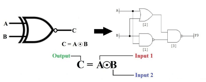
Figure 8: Exclusive-NOR Gate
The Exclusive-NOR (Ex-NOR) gate functions as the complement to the XOR gate, playing a required role in digital systems that evaluate input uniformity. It is needed for applications requiring consistent checks or parity evaluations in digital transmissions.
This gate is extensively employed in digital circuits to verify the uniformity or equality of input signals, making it a required tool for guaranteeing data integrity. This gate is commonly used in error-checking processes to compare bits from two different sources, confirming their match to guarantee error-free data transmission. For effective use, operators and technicians need to be well-versed with the Ex-NOR gate's strict output conditions—it delivers a high output only when all inputs are exactly equal. This requirement for precise input alignment and synchronization places significant demands on the configuration and maintenance of digital systems, especially in applications like data verification systems and digital parity checkers that depend heavily on strict data congruency.
Different Types of Exclusive-NOR Gate
• Standard CMOS XNOR Gate - This is the most common type used in digital circuits. It typically consists of an arrangement of CMOS (Complementary Metal-Oxide-Semiconductor) transistors that achieve low power consumption and high noise immunity. This gate is ideal for battery-operated devices due to its power efficiency.
• TTL XNOR Gate - TTL XNOR gates are made with bipolar transistors and are known for their fast switching times, making them suitable for high-speed operations. However, they tend to consume more power compared to CMOS gates.
• Pass-Transistor XNOR Gate - This type uses pass-transistor logic, which can be more area-efficient than standard CMOS logic. It often results in faster operation and reduced transistor count, which is advantageous in high-performance and compact digital circuits.
• Quantum-dot Cellular Automata (QCA) XNOR Gate - A newer technology, QCA uses the position of electrons rather than current flow for logic operations, offering the potential for extremely low power consumption and high processing speeds. It's still largely in the research and development phase.
• Optical XNOR Gate - This type uses optical signals instead of electrical signals, making it useful in optical computing and communication systems where high bandwidth and immunity to electromagnetic interference are required.
Conclusion
Throughout this exploration of digital logic gates, we have seen how these basic components compose the symphony of digital processing. From the simplicity and foundational role of NOT gates in signal inversion to the nuanced applications of XOR and XNOR gates in error detection and correction, each gate type brings unique characteristics and advantages to digital circuit design. The contrast between TTL and CMOS technologies further enriches the landscape, offering designers choices that impact system performance based on power consumption, speed, and noise immunity. The practical applications highlighted—ranging from basic arithmetic operations to sophisticated security and data integrity systems—illustrate the dangerous role these gates play across various technological domains. As technology evolves, the continuous improvement and adaptation of these gates will be core in meeting the increasing demands for faster, more efficient, and more reliable digital systems. This journey through the intricacies of digital logic gates not only enhances our understanding of electronic principles but also highlights the relentless innovation driving the electronics industry forward.
Frequently Asked Questions [FAQ]
1. What devices use logic gates?
Logic gates are basic components in digital circuits and are extensively used in devices such as computers, smartphones, and other electronic appliances. They are also integral in the operation of automated systems like traffic lights and modern industrial equipment.
2. How to find the output of logic gates?
The output of a logic gate is determined by applying the input values to the specific logic function of the gate (such as AND, OR, NOT, NAND, NOR, XOR, XNOR). For instance, an AND gate will output a high signal (1) only if all its inputs are high. You can use truth tables to easily determine the output for all possible input combinations.
3. What are the advantages of logic gates?
Logic gates are simple, reliable, and can be used to create complex circuits through combination. They allow for the construction of digital systems that are scalable, easily modifiable, and capable of processing information efficiently. Their predictability and binary nature make them ideal for applications requiring precise control and decision-making.
4. Is the logic gate hardware or software?
Logic gates are primarily hardware components made from semiconductor materials like silicon. They exist physically in integrated circuits or microchips. However, the concept of logic gates can also be simulated in software for educational purposes or digital circuit design.
5. What are the precautions of logic gates?
When using logic gates, it's beneficial to consider factors like voltage levels, compatibility with other components, and the avoidance of loading too many devices onto a single output, which can lead to signal integrity issues. Additionally, ensure proper handling to avoid static damage and adhere to the manufacturer's specifications for optimal performance.