How Build a Programmable LED QR Code?
QR codes are compact, two-dimensional barcodes that store a variety of information and are easily accessible with a smartphone camera. Originally created in Japan during the early 1990s to track parts in the automotive industry. A programmable LED QR code is a dynamic display system that uses an array of light-emitting diodes (LEDs) to create QR codes and can be updated instantly. The main goal of developing a programmable LED QR code system is to increase the versatility and usability of QR codes in different environments.This article explains how to build a programmable LED QR code display, covering everything from picking the right hardware to setting up and testing the final product. It goes into details about choosing a microcontroller, using MAX7219 integrated circuits to control the LEDs, and programming with tools like Arduino IDE. It focuses on the practical use of electronic parts and software while also offering tips on troubleshooting and customizing the project to improve its features.
Catalog
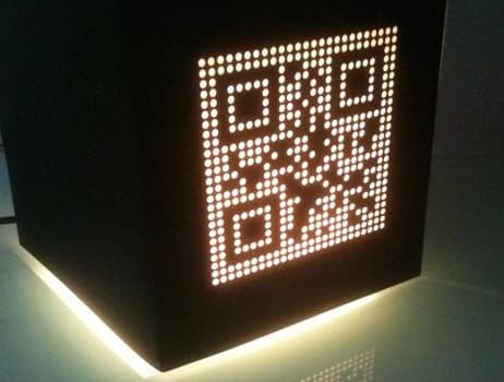
Figure 1: LED QR Code Project
Materials
LED Matrix Panel
The LED matrix panel is your main display, where the QR code will be visualized. Select a panel with sufficient resolution to ensure the QR code is easily scannable. A 32x32 or 64x64 RGB LED matrix provides enough clarity for this purpose.
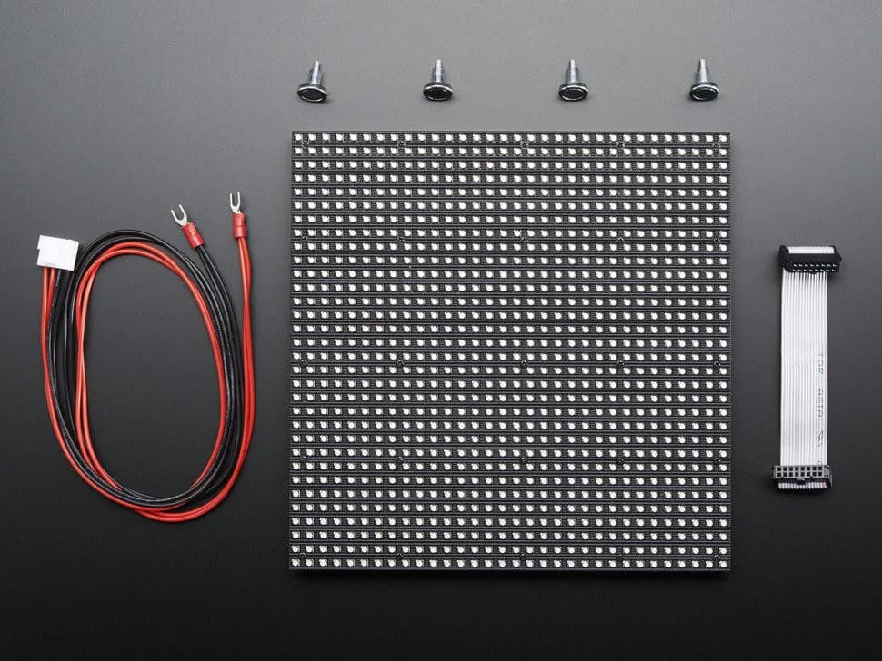
Figure 2: LED Matrix Panel
Microcontroller
You need a microcontroller to control the LED matrix. Options include an Arduino, Raspberry Pi, or ESP32. Choose one based on your level of experience and the availability of suitable libraries to control the LED matrix efficiently.
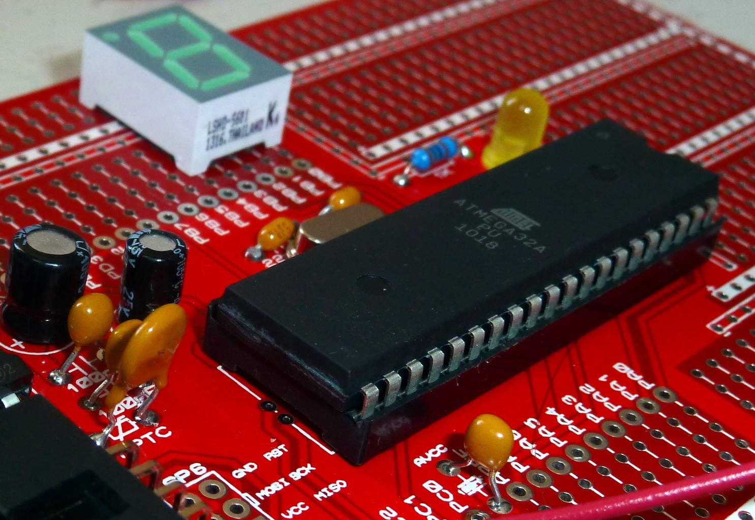
Figure 3: Microcontroller
Power Supply
A reliable power supply is important, as LED matrices can consume power, especially at higher brightness settings. Ensure the power supply matches the specific voltage and current requirements of your chosen LED matrix.
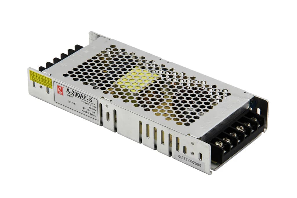
Figure 4: Power Supply
Connecting Cables
To link your microcontroller to the LED matrix, you'll need various cables. These might include jumper wires or a ribbon cable, depending on the connection type of your LED matrix.
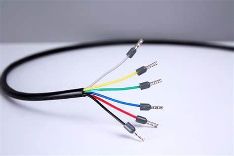
Figure 5: Connecting Cables
Computer
A computer is required to program the microcontroller.

Figure 6: Computer
QR Code Generation Software
You'll need software or an online tool to create the QR codes.
LED Matrix Driver
Depending on the microcontroller and LED matrix you opt for, a dedicated driver or shield might be need to control the matrix effectively. For instance, if you're using an Arduino, the Adafruit RGB Matrix Shield can be a helpful addition.
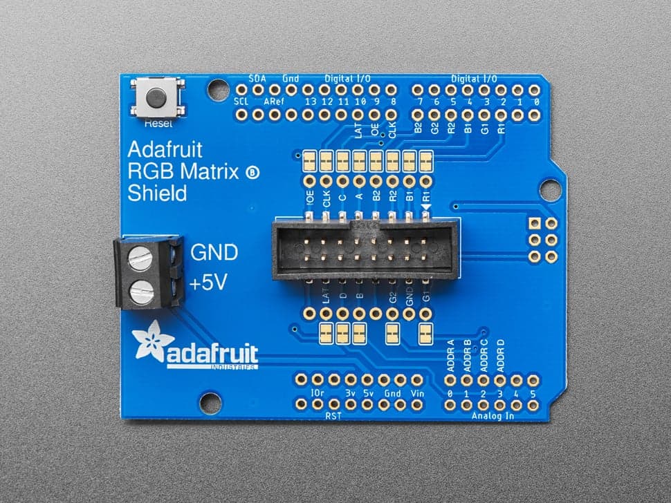
Figure 7: LED Matrix Driver
Tools
Soldering Iron
You'll need a soldering iron if your LED matrix or the connections between components require soldering. It’s good for creating stable and permanent electrical connections.
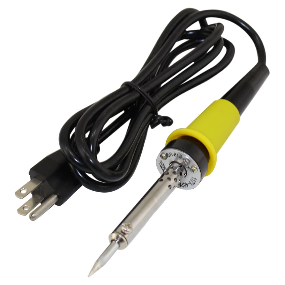
Figure 8: Soldering Iron
Wire Cutters/Strippers
These tools are used for preparing your cables, allowing you to cut wires to the desired length and strip away the insulation to expose the conductive material inside.

Figure 9: Wire Cutters/Strippers
Computer with Arduino IDE or Other Development Environments
A computer is required for writing and uploading code to your microcontroller. The Arduino IDE or another suitable development environment will allow you to program and manage your hardware effectively.
Multimeter
A multimeter is invaluable for troubleshooting. It helps you verify that all your connections are correct, safe, and functioning as expected by measuring voltage, current, and resistance.
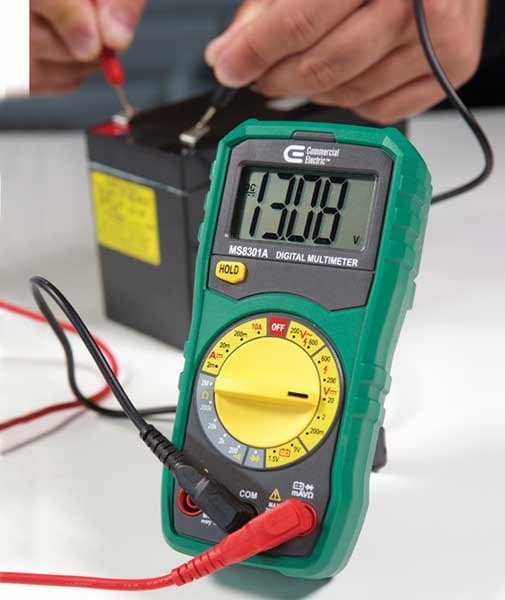
Figure 10: Multimeter
Building a Programmable LED QR Code Display
Setting Up the LED Matrix with MAX7219 ICs
To start setting up an LED matrix on a breadboard, first, place the LED matrix carefully. Each pin on the matrix corresponds to either a row or a column, so it's important to match these correctly with the matrix's layout. Misalignment here can cause issues in controlling the LEDs later on. Confirm each pin's role before moving forward.
Next, the MAX7219 integrated circuit needs to be connected to the LED matrix. Begin by supplying power to the IC—connect the VCC pin to a 5V source and the GND pin to the circuit's ground. Then, focus on connecting the MAX7219’s DIG (digit) and SEG (segment) lines to the respective rows and columns of the LED matrix. Correct alignment between the matrix and the IC pins help proper operation. If the pinout is unclear, consult the datasheet for guidance.
If your project requires multiple LED matrices, you'll need to daisy-chain additional MAX7219 ICs. Start by connecting the ‘Data Out’ pin of the first MAX7219 to the ‘Data In’ pin of the next IC. Continue this pattern, linking the ‘Load’ and ‘Clock’ lines between each IC. This configuration allows multiple matrices to be controlled in sequence with minimal use of microcontroller pins. Proper synchronization between all ICs ensures smooth operation across the entire display setup.
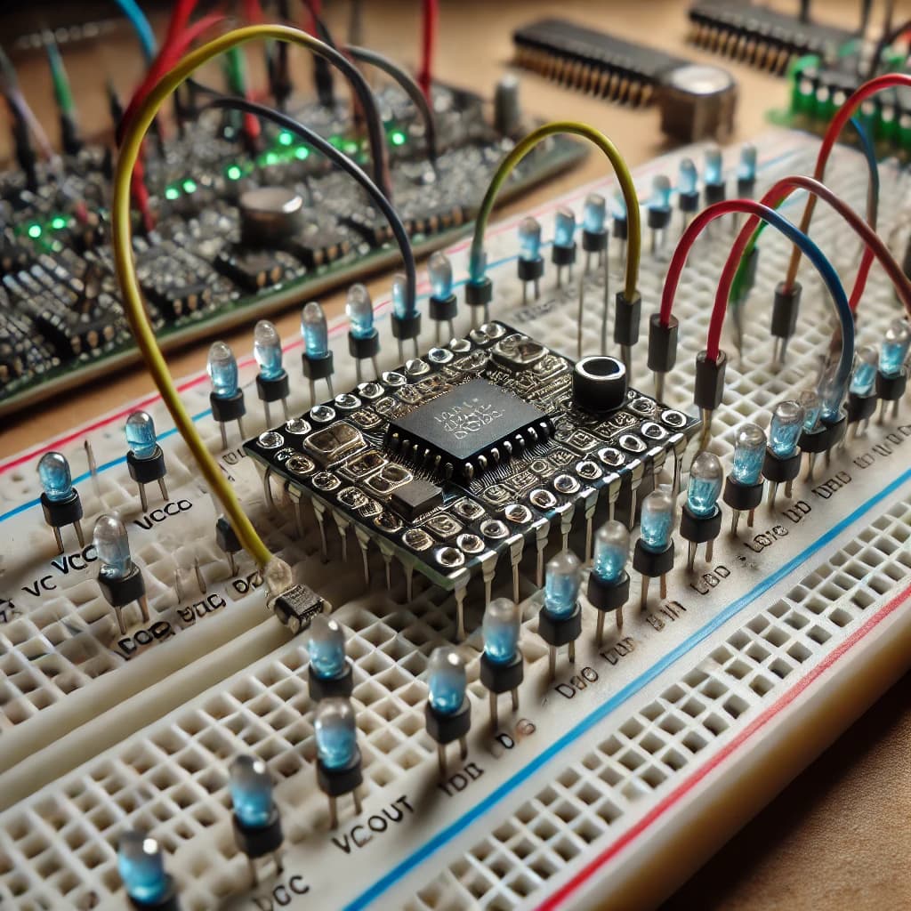
Figure 11: Setting Up the LED Matrix with MAX7219 ICs
Programming the Arduino and Troubleshooting
With the hardware in place, the next step is programming the Arduino. Start by including the libraries, the LedControl.h library is used for interfacing with the MAX7219 IC. Within your Arduino sketch, initialize the LED matrix by defining how many MAX7219 ICs are in use and specify the communication pins (DataIn, CLK, LOAD).
In the main loop of your code, you can control individual LEDs, or display entire characters or numbers. Use library functions to send data to specific LEDs, adjust brightness, or clear the display as required.
During testing, you might encounter common issues like poor connections or software bugs. For example, an LED matrix may flicker or display incorrectly if there’s a missing ground connection. Double-check all ground connections to ensure they’re secure.
Another common problem is incorrect wiring in daisy-chained setups. Use a multimeter to check continuity and verify that all connections match your schematic. Software issues can also cause problems, such as the Arduino code not initializing or addressing the MAX7219 ICs correctly. Ensure that your pin assignments in the code are correct and that all loops function as intended without disrupting the data flow between devices. Debugging might involve reviewing the logic in your code and ensuring that all devices are properly addressed.
Constructing the Final Matrix
The first step in this process is putting together the LED matrices into a bigger setup, involves a few careful actions. Start by gathering all the materials, like LED matrix panels, connecting cables, screws, spacers, and mounting brackets. Then, plan the layout by arranging the matrices on a flat surface, making sure they are all facing the same way, with the power and data connectors aligned, and deciding on the overall size and arrangement, such as a 3x3 or 4x4 grid.
Once the layout is set, begin mounting the matrices by securely attaching the brackets to the back of each panel. These panels should then be fixed onto a sturdy backing material, like plywood or acrylic, to keep everything stable. It's important to place spacers between each panel to allow for heat to escape and to prevent light from one panel interfering with another.
After mounting, focus on connecting the data lines. Start by linking the data input of the first matrix to your control system, like a microcontroller or PC. Then, connect the data output from the first matrix to the data input of the next, and keep this pattern going through all the matrices. Once the data is connected, secure the power connections by attaching power cables to each matrix, making sure the connections are tight to avoid power loss. Use cable ties or clamps to keep the cables organized and reduce the chance of accidental disconnections or damage.
Once everything is connected, move on to the final setup and testing. Turn on the system and run a test pattern to check for any LEDs that aren't working or connection problems. If there are any issues, adjust the cable connections or replace any faulty LED panels as required.
The second important part of building a large LED matrix is managing power needs. Start by calculating how much power you’ll need: check how much power each matrix panel uses (usually given in watts) and multiply that by the total number of panels to figure out the overall power requirement. Consider both the peak and average power needs, since LEDs use more power when displaying bright colors, especially white.
Next, design the power distribution system. Choose a power supply that can handle the total power requirement, adding an extra 20% for safety. Split the power load across several power supplies to avoid overloading one. Use terminal blocks that can handle the total current to distribute power efficiently from one input to multiple outputs. Connect the main power supply to the terminal block, then run individual power wires from the terminal block to each matrix panel, making sure all connections are tight and using wires that can carry the current without overheating.
Finally, put safety measures in place. Install fuses or circuit breakers close to the power source to protect against potential overcurrent. Regularly check all connections and wires for wear or damage, and replace any parts to keep the system safe and reliable.
Programming, Uploading and Configuring the Code
Microsoft Excel, known for its data management and analytical functions, can also be creatively used for programming tasks such as setting up QR code displays. To begin, identify the data you wish to encode in the QR code, which could be text, a URL, or other information. Since Excel doesn't natively generate QR codes, you'll need to install an add-in like the QR Code Generator from the Microsoft Office Add-ins store. After entering your data, the add-in will generate a QR code directly within an Excel cell.
After generating the QR code, you can customize it by changing its size and adjusting the error correction level. This makes the code stronger against damage but also more complex. After finalizing the QR code, export it as an image file, such as PNG or JPEG. This image can then be imported into your programming environment, where it needs to be converted into a format like a byte array if you plan to display it on a microcontroller like an Arduino. This method allows programmers to quickly prototype and test QR codes for various projects using Excel’s user-friendly interface and powerful add-in capabilities.
Uploading code to an Arduino is a basic skill for anyone using these microcontrollers. First, ensure that the Arduino IDE is installed on your computer, as this is where you will write, compile, and upload your code. Develop your Arduino sketch within the IDE, including the libraries if your project involves displaying a QR code. Before uploading, verify that your Arduino board is properly connected to your computer via a USB cable and select the correct board model and port in the IDE. For safety, disconnect any external power sources from the Arduino during the upload process to prevent short circuits or power surges. Once everything is set up, click the upload button in the Arduino IDE. You'll see the progress in the bottom console and a success message will appear once the upload is complete. After uploading, reconnect any external power supplies and test the Arduino to ensure everything functions as expected.
Mounting and Final Setup
To start putting together your programmable LED QR code, first attach the LED matrix to a solid base like plywood. This helps keep the matrix steady and looking good. Choose a piece of plywood that is a bit bigger than the matrix and thick enough to support the weight without bending, a half-inch thickness works well. Place the LED matrix on the plywood to find the best spot for it. This step helps you make sure everything is lined up properly and that there's enough room around the edges for any wires or components.
Once you've marked the best position on the plywood, you can mount the matrix. If your LED matrix doesn't have pre-drilled holes for mounting, you might need to build a simple frame or use brackets. You can make a frame using wooden strips or metal brackets, securing it around the matrix's edges and attaching it to the plywood. Make sure the frame holds the matrix firmly without covering any LEDs.
For a nicer look, consider painting or staining the plywood to match the area where the QR code will be displayed. Dark colors, like black, often make the LED colors stand out more. You could also add a clear acrylic cover over the matrix to protect the LEDs from dust and damage while still keeping them visible.
Organize the cables on the back of the plywood using cable clips. This makes it look neat and ensures the wires are safe, preventing them from coming loose or getting damaged over time.
Final Testing
After putting everything together, it's important to test your LED QR code to make sure it works well and can be easily scanned from different distances and angles. Start by checking that all connections are secure and that the LED matrix is getting power. Turn on the matrix and make sure every part of the QR code lights up correctly.
Next, check how well the QR code can be read by moving farther away from it. The code should be easy to scan from at least the minimum distance you expect people to use it from. Use a QR code reader on a smartphone or tablet to test it from different distances and angles. It should be scannable without needing to find an exact spot, making it easy to use in real-life situations.
If you plan to use your LED QR code outdoors or in places with changing light, test how visible it is under different lighting conditions. For example, direct sunlight might make it harder to see the LED display. If this happens, you may need to add a shade or increase the brightness of the LEDs to make it easier to see.
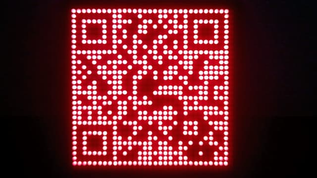
Figure 12: Finished LED QR Code Project
Conclusion
Creating a programmable LED QR code display involved detailed electronic work and advanced programming, leading to a functional and interesting product. The project required choosing and putting together an LED matrix, picking the right microcontroller, ensuring a steady power supply, and carefully managing all the connections. Every step, from setting up the LED matrix with MAX7219 chips to programming the Arduino, require close attention to detail, showing how important precision is in both electronics and coding.
The project also stressed the need for careful planning and testing to make sure the QR codes could be scanned and worked well under different lighting conditions. It is not only offered valuable learning but also resulted in a versatile digital display tool that combined technology with creativity. It provided useful insights for future projects in embedded systems and digital interfaces. The knowledge gained will definitely improve future work in electronics and programming.
Frequently Asked Questions [FAQ]
1. Can I make my own dynamic QR code?
Yes, you can create your own dynamic QR code. Dynamic QR codes are editable and trackable, allowing you to change the URL or data linked to the QR code without needing to generate a new code. To create one, you'll need to use a QR code generator that supports dynamic QR codes. These services require you to create an account, as they host the data that the QR code links to and provide analytics.
2. Can Canva generate a QR code?
Yes, Canva can generate QR codes. It offers a simple tool within its design platform to create static QR codes. You can input a URL or other data, and Canva will produce a QR code that can be incorporated into your designs. However, Canva does not support the creation of dynamic QR codes, the QR codes made in Canva are static, meaning the information they encode cannot be changed once created.
3. Do QR codes expire?
QR codes themselves do not expire. A QR code will continue to work as long as the data encoded in it remains valid. However, if you are using a dynamic QR code, the URL or data it redirects to can be changed or deactivated, affecting the QR code's functionality. Similarly, if the QR code links to a web page that no longer exists or has been moved without redirection, the QR code will lead to an error page.
4. What software can create a QR code?
Several software options are available for creating both dynamic and static QR codes, each offering unique features. Popular choices include QR Code Generator that provides the ability to create dynamic and static QR codes with options for customization and tracking. Adobe Spark offers tools to create static QR codes that can be integrated into larger design projects. Google Chrome has a built-in QR code generator for any webpage you are visiting, making it a convenient option for quick QR code creation. QR Stuff allows you to create static QR codes for various data types, with some limited options for dynamic QR codes. These tools range from simple static QR code generators to more advanced platforms that offer extensive customization and tracking capabilities.
5. Is it safe to create your own QR code?
Yes, creating your own QR code is generally safe. The safety concerns associated with QR codes are not about the creation process but rather where the QR code directs users and what data is encoded. Ensure the URLs or data embedded are secure and from trusted sources. When using dynamic QR codes, it's important to use a reputable QR code management service to prevent misuse or unauthorized edits. Always monitor where your QR code links to ensure it remains a safe destination for users.