Guide to Understanding SCRs: Discovering the Dynamics, Functions, and Symbols of Thyristors
Silicon Controlled Rectifiers (SCRs), or thyristors, mark a significant development in semiconductor technology, adept at handling high-power electrical applications. Their unique four-layer p-n-p-n structure offers superior performance compared to traditional bipolar transistors, enabling more effective and reliable electrical power control. SCRs are helpful in diverse applications, from industrial motor controls to household lighting systems, demonstrating their versatility and importance in electronic circuits.This article explores the detailed operation, applications, and technical details of SCRs, highlighting their operational principles and structural characteristics. It also explains how these devices are utilized for efficient power management. By digging into the basics of SCR technology, including their construction, activation mechanisms, and widespread applications in various electronic fields, the article illustrates why SCRs are favored over other semiconductor devices for their efficiency, reliability, and adaptability to evolving technological needs.
Catalog
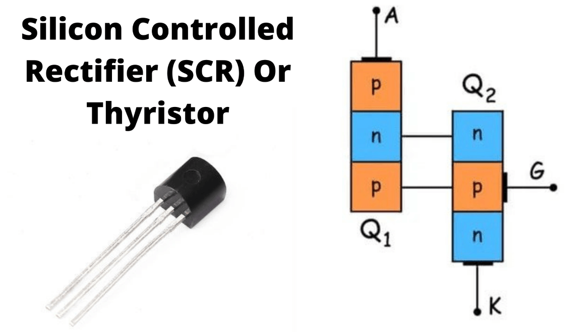
Figure 1: SCR or Thyristor
Exploring the Basics of SCR or Thyristor
An SCR, or Silicon Controlled Rectifier, commonly referred to as a thyristor, is a type of semiconductor device. It stands out due to its four-layer structure, alternating between p-type and n-type materials in a sequence: p-n-p-n. This design differs from the more common three-layer structure found in bipolar transistors, which are either p-n-p or n-p-n.
Unlike bipolar transistors, which have three terminals called the collector, base, and emitter, an SCR has three distinct terminals: the anode, the cathode, and the gate. The anode is connected to the outermost n-type layer, while the cathode is linked to the outermost p-type layer. The gate terminal, serving as the control input, is attached to the inner p-type layer, close to the cathode.
SCRs are typically made from silicon because of its ability to handle high voltages and currents, which is useful for power applications. Silicon is also chosen for its excellent thermal properties, allowing SCRs to maintain performance and durability even under varying temperatures. In addition, the extensive development of silicon semiconductor technology has made SCRs both cost-effective and reliable. Silicon’s well-established processing methods contribute to its widespread use in the semiconductor industry, offering significant advantages in terms of cost, reliability, and manufacturing efficiency.
Mechanics of SCR Conduction and Triggering
The operation of an SCR (Silicon Controlled Rectifier) involves specific conduction and triggering processes. When the gate terminal is not activated, the SCR functions similarly to a Shockley diode, remaining in a non-conductive state until a certain condition is met. One way to bring the SCR into conduction is by reaching a breakover voltage, a specific voltage threshold between the anode and cathode that triggers conduction. Alternatively, a rapid increase in voltage between these terminals can also initiate conduction.
A more controlled method of triggering the SCR involves the gate terminal. Applying a small voltage to the gate activates the lower internal transistor. This activation causes the upper transistor to turn on, resulting in a self-sustaining flow of current through the SCR. This method, known as gate triggering, is widely used in practical applications because it allows for precise control of high-power circuits.
Deactivating an SCR, or turning it off, can be done through a process known as reverse triggering. This involves applying a negative voltage to the gate relative to the cathode, which turns off the lower transistor and interrupts the current flow, thereby halting conduction. However, reverse triggering is not commonly used because it is difficult to divert enough current away from the upper transistor to be effective. Advancements such as the Gate-Turn-Off (GTO) thyristor have improved the ability to deactivate SCRs by allowing the gate current to directly turn off the device.
Basic Operations of SCR/Thyristors
An SCR, or Silicon Controlled Rectifier, functions in three basic states: reverse blocking, forward blocking, and forward conducting.
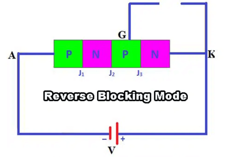
Figure 2: Reverse Blocking
In this state, the SCR acts like a diode that is reverse-biased, preventing any current from flowing backward through the circuit. This blocking mode is insistent on ensuring that the current only flows in the desired direction.
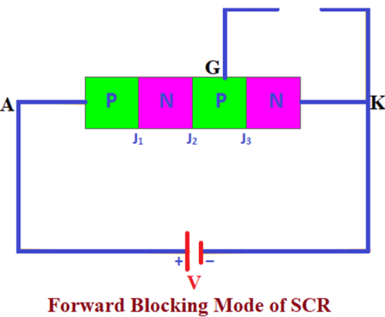
Figure 3: Forward Blocking
When the SCR is forward-biased but not yet triggered, it remains in a non-conductive state. Even though the voltage is applied in the forward direction, the SCR won't allow current to pass through until a signal is sent to the gate terminal. This state is suitable for controlling when the SCR will start conducting.
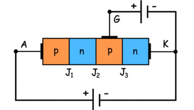
Figure 4: Forward Conducting
Once the gate receives a trigger, the SCR switches to the forward conducting state, allowing current to flow freely through the device. The SCR will continue to conduct until the current drops below a certain threshold, known as the holding current. When the current falls below this level, the SCR automatically returns to its non-conductive state, ready to be triggered again.
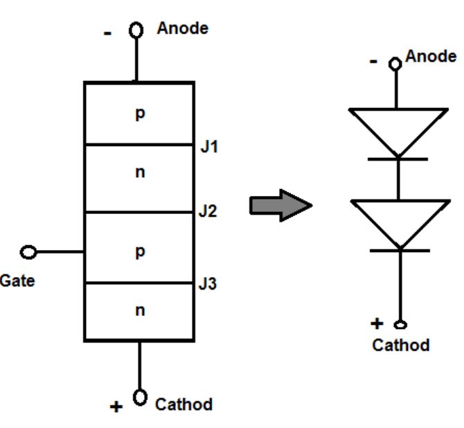
Figure 5: Construction of SCR
How SCRs Are Built?
The SCR, or Silicon Controlled Rectifier, is built with a layered structure of either NPNP or PNPN types, consisting of three key junctions—J1, J2, and J3—that are dominant to its functionality. The anode is connected to the outer P-layer (in the PNPN structure), while the cathode is linked to the outer N-layer. The gate terminal, which controls the SCR’s operation, is connected to one of the inner layers.
This specific arrangement of layers and junctions allows the SCR to effectively manage and control high-power loads. The design settles for the SCR's ability to switch and regulate large amounts of electrical power, which is why it is widely used in various industrial and commercial applications. The layered structure not only supports the basic operational modes of the SCR but also provides the durability needed to handle significant electrical stresses, ensuring reliable performance in demanding environments.
Various Types of Silicon-Controlled Rectifiers
Silicon Controlled Rectifiers (SCRs) are beneficial in power electronics, offering various types of options to meet different application needs.
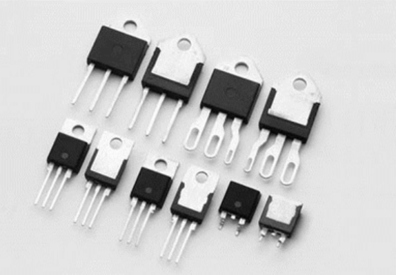
Figure 6: Standard SCRs
These are the most commonly used SCRs, designed for general-purpose applications that require moderate power handling. They are versatile and reliable, making them suitable for a wide range of uses. An example is the BT151, often employed in circuits where basic power control is needed.
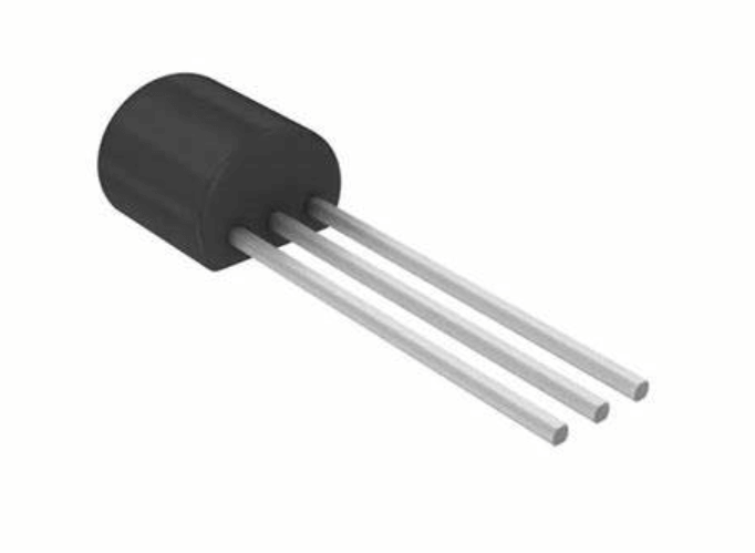
Figure 7: Sensitive Gate SCRs
These SCRs are designed to operate with low gate trigger currents, making them ideal for interfacing with logic circuits and other low-power control systems. The 2P4M is a common model in this category, allowing easy triggering from digital circuits without the need for high-power gate signals.
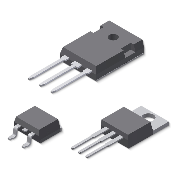
Figure 8: High Power SCRs
These SCRs are built to handle high voltage and current, making them suitable for industrial applications such as motor drives and power converters. The TYN608 is an example of a high-power SCR, capable of managing substantial electrical loads in demanding environments.
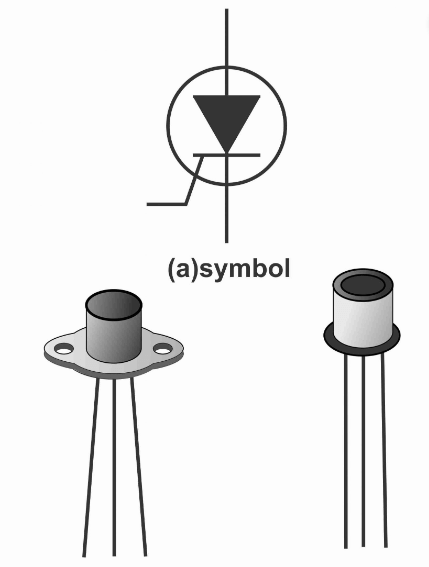
Figure 9: Light Activated SCRs (LASCRs)
These SCRs are triggered by light instead of electrical signals, making them useful in applications that require high isolation or where electrical triggering is impractical. LASCRs provide a unique solution for specific high-isolation needs.
Applications of SCRs and Thyristors in Modern Electronics
Thyristors, also known as SCRs, play a key role in various electronic fields because of their strong power control capabilities. In managing AC power, they are dynamic for adjusting the performance of lighting systems, motors, and other devices. This adjustment helps in optimizing energy use and improving control accuracy. SCRs are particularly effective in AC power switching, where they ensure smooth transitions within complex electronic circuits. This reliability is core to maintaining the overall performance and stability of these systems. For overvoltage protection, thyristors are used in crowbar circuits within power supplies. When a voltage surge occurs, these circuits quickly short-circuit the power supply output to prevent damage to electronic components, effectively protecting the equipment from potential failures.
Thyristors also play a significant role in phase angle controllers. These controllers adjust the firing angle of SCRs to regulate power output with precision. This precise control is especially significant in applications that require fine-tuned power adjustments, such as industrial heating systems. In photography, thyristors control the timing and intensity of camera flash units, allowing photographers to achieve accurate light exposure.
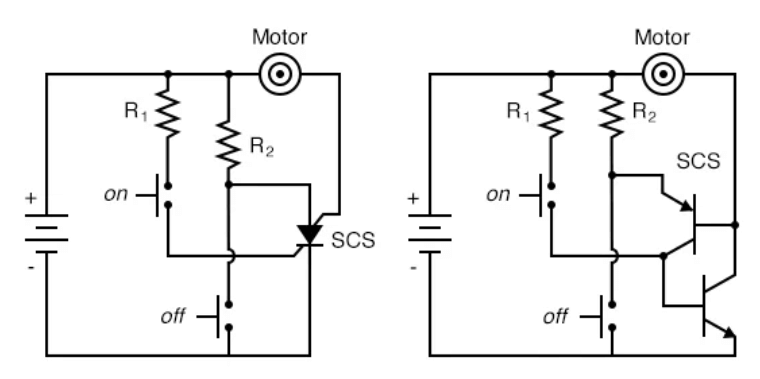
Figure 10: Thyristor Latches
Latching Process of Thyristors
Once the thyristor is triggered and begins conducting, simply cutting off the gate current is not enough to turn it off. To deactivate the thyristor, the main current flowing between the anode and cathode must be reduced below a specific threshold or completely stopped. This is usually done by de-energizing the circuit or diverting the current elsewhere.
This behavior is due to the thyristor's bistable nature, meaning it stays in its conducting state until an explicit action is taken to stop it. This latching feature makes the thyristor highly effective at controlling and managing power flow in various applications. However, it also requires careful circuit design to ensure the thyristor can be reliably turned off when needed.
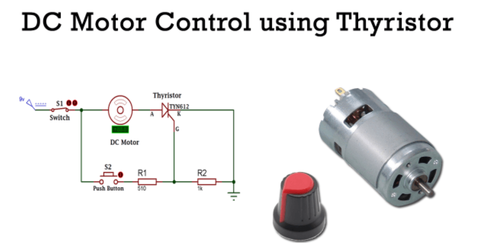
Figure 11: DC Motor Control Using SCR
Controlling DC Motors Using SCR
SCRs are suitable for controlling the speed of DC motors by adjusting the voltage supplied to the motor's armature. In this system, SCRs are configured to manage both the positive and negative cycles of the input power, allowing for precise control over the motor’s speed.
The key to this control lies in the timing and duration of the SCR’s conduction phase. By carefully adjusting when the SCRs turn on and off, the average voltage applied to the motor can be finely tuned. This results in smooth and responsive speed regulation, making it possible to achieve granular control over the motor's performance.
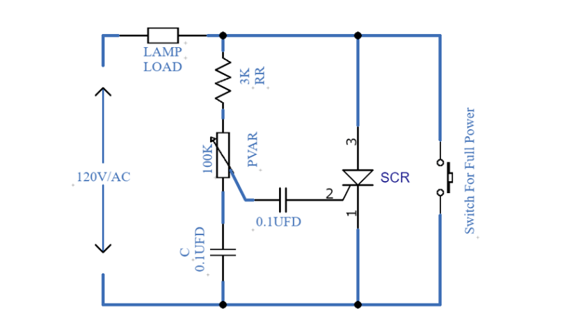
Figure 12: AC Motor Control Using SCR
Optimizing AC Motor Control with SCR Technology
SCRs are dynamic for controlling the speed of AC motors by adjusting the voltage supplied to the stator. To achieve this, SCRs are arranged in anti-parallel configurations across each phase of the motor. This configuration allows for greater flexibility and effectiveness in power modulation, which directly impacts motor speed.
The core of this control lies in the precise triggering of the SCRs to adjust the phase angle of the voltage applied to the motor. By carefully timing when the SCRs activate, the system can finely tune the motor's speed to meet specific operational needs. This method provides a reliable and efficient way to manage varying load conditions, ensuring that the motor operates smoothly and effectively across a range of speeds.
Key Benefits of Silicon-Controlled Rectifiers
Silicon Controlled Rectifiers (SCRs) are increasingly favored in modern electronics due to their distinct advantages over traditional mechanical switches.
|
Advantages of Silicon-Controlled
Rectifiers |
|
|
High Efficiency and Fast Switching |
SCRs excel at efficiently controlling
power, with minimal energy loss during switching. Unlike mechanical switches,
which suffer from wear and tear, SCRs can switch on and off rapidly without
the need for moving parts. This fast switching makes them ideal for
applications requiring precise control over high voltages and currents, such
as motor speed controllers, power regulators, and variable-frequency drives. |
|
Compact and Silent Operation |
SCRs are solid-state devices, allowing
them to be much smaller than bulky mechanical switches. Their compact size
makes them easy to integrate into tightly packed electronic circuits.
Additionally, they operate without any mechanical noise, making them suitable
for environments where quiet operation is valuable or where noise could
interfere with other processes. |
|
Reliability and Longevity |
The absence of moving parts in SCRs
significantly enhances their reliability and lifespan. Mechanical switches
often degrade over time due to friction, wear, and environmental factors like
dust and moisture. In contrast, SCRs are less prone to these issues, ensuring
longer operational life and reducing maintenance needs. |
|
Greater Control and Flexibility |
SCRs offer superior control over power
delivery, allowing for precise adjustments to voltage and current in a
circuit. This capability is used in applications requiring fine-tuned power
settings, such as power supplies and lighting dimmers. Additionally, SCRs can
be easily triggered by small gate signals, making them compatible with modern
digital control systems. |
|
Robust Performance in Harsh
Environments |
SCRs are designed to operate reliably
under extreme conditions. They can withstand high temperatures and are
resistant to voltage spikes and surges, making them ideal for industrial
applications where ruggedness is required. Their durability ensures
consistent performance in challenging environments where mechanical switches
might fail. |
|
Enhanced Safety Features |
SCRs allow for the easy implementation of
safety features like fault detection and automatic shutdown. They can be
quickly turned off by removing the gate current, providing a rapid way to cut
power in the event of an overload or short circuit, which maintains safety in grave systems. |
|
Cost-Effectiveness |
While SCRs may have a higher upfront cost
compared to some mechanical switches, their long lifespan and low maintenance
requirements make them more economical in the long run. The energy savings
from their efficient operation also contribute to their overall
cost-effectiveness, making them a smart investment for many applications. |
|
Environmental Friendliness |
SCRs are environmentally friendly due to
their efficiency and longevity. Their durability reduces the need for
frequent replacements, and their efficient operation minimizes energy waste,
supporting sustainable practices in power management and electronics design. |
Conclusion
To put it briefly, Silicon Controlled Rectifiers (SCRs) stands out as a cornerstone of power electronics, useful for their high efficiency, reliability, and precision with which they manage power flows in various applications. Their ability to operate in harsh environments and maintain functionality under extreme conditions makes them requisite in industrial settings, where robustness and longevity are dominant.
In addition, the detailed examination of their operation—from the basic blocking and conducting states to sophisticated control mechanisms like phase angle adjustment and reverse triggering—reveals the depth of engineering ingenuity embedded in SCR technology. As we advance further into an era dominated by the need for sustainable and efficient power solutions, SCRs will likely continue to play a dynamic role, driven by ongoing innovations and improvements in semiconductor processing. Their contribution not only spans multiple industries but also paves the way for future developments in electronic design and power management, ensuring that SCRs remain at the forefront of technological advancements.
Frequently Asked Questions [FAQ]
1. How does a silicon-controlled rectifier SCR work?
An SCR operates as a switch to control electrical power in circuits. It has three terminals: anode, cathode, and gate. When a small voltage is applied to the gate, it allows the SCR to conduct electricity between the anode and cathode, effectively turning it "on." Once on, the SCR will continue to conduct electricity, even if the gate voltage is removed until the current flowing through it drops below a certain level or the circuit is interrupted.
2. What is the function of a thyristor-controlled rectifier?
A thyristor-controlled rectifier uses thyristors (a type of semiconductor device that includes SCRs) to convert alternating current (AC) to direct current (DC). It controls the power output by adjusting the phase angle at which the thyristors are triggered, thus controlling the amount of current allowed to pass through during each cycle of the AC input.
3. What is the main function of SCR?
The primary function of an SCR is to control the flow of electricity in a circuit. It acts as a switch that can be turned on or off, or even partially on, to regulate power in applications ranging from dimming lights to controlling the speed of motors.
4. How does a controlled rectifier work?
A controlled rectifier uses devices like SCRs to control the conversion of AC to DC. By triggering the SCRs at specific times during the AC cycle, the rectifier can adjust the voltage and current output on the DC side. This is useful for applications where variable DC output is needed, such as in battery charging or speed control in DC motors.
5. How does a thyristor controller work?
A thyristor controller works by adjusting the timing of when thyristors within a circuit are triggered. This timing adjustment, known as phase angle control, allows for precise control over how much power is delivered to the load. By delaying the triggering point of the thyristors in an AC cycle, the controller can reduce the power output, and by triggering them earlier, it can increase the power output.