Guide to Mastering the SWR/VSWR Meter for Optimal Performance
The Standing Wave Ratio (SWR) meter is a grave tool in radio communications, dynamic for evaluating energy transmission efficiency between a transmitter and its antenna. As radio frequency (RF) systems grow more complex, the need for precise operation increases. Known also as the Voltage Standing Wave Ratio (VSWR) or Impedance Standing Wave Ratio (ISWR) meter, the SWR meter measures SWR on transmission lines or antenna feeders. This data is useful for ensuring that the transmitter’s feeder and the antenna are well-matched, optimizing energy use and maximizing effective radiation.This article explores the technical details, practical applications, and serious importance of SWR meters in modern RF communication systems, offering a thorough guide from setup to troubleshooting, emphasizing their significant role in improving communication reliability and efficiency.
Catalog
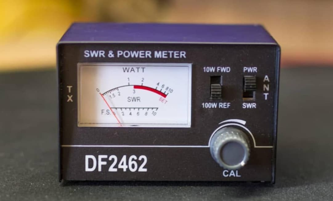
Figure 1. SWR Meters
Introduction to SWR Meters
The SWR (Standing Wave Ratio) meter is a dominant tool in radio communications. It measures the standing wave ratio on transmission lines or antenna feeders, ensuring effective energy transmission. Sometimes referred to as a VSWR (Voltage Standing Wave Ratio) or ISWR meter, its main purpose is to assess how well the impedance between a transmitter's feeder and its antenna matches. This matching is useful for efficient Radio Frequency (RF) energy transmission.
The SWR meter's job is to determine the ratio of RF energy that gets reflected to the transmitter compared to the energy that is successfully radiated. Ideally, an SWR reading of 1:1 signifies a perfect match, where all the transmitted energy is fully utilized without any being reflected. Achieving a low SWR is noteworthy as it means the transmission is efficient and energy loss is minimized.
Most SWR meters operate using a dual-directional coupler that samples the RF energy flowing in one direction. Inside the meter, a diode rectifies this sample, allowing for an accurate measurement. In some models, only a single directional coupler is used, and the user must manually rotate the meter to measure the energy flow in both directions of the transmission line. While SWR meters are generally very accurate at higher frequencies, their performance can decline at lower frequencies, particularly when the transmission lines are too long to be practical.
Setup of the SWR Meter
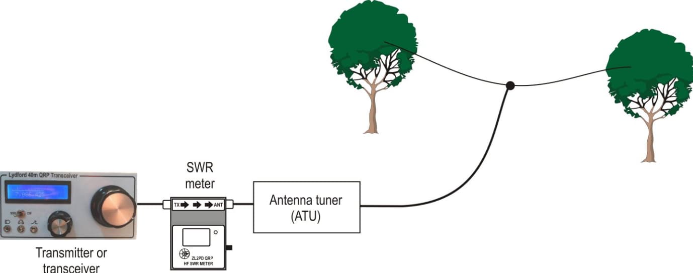
Figure 2: VSMR Installed Between the Transmitter and The Antenna
Setting up a VSWR (Voltage Standing Wave Ratio) meter is generally straightforward, but it requires careful attention to detail to avoid common mistakes. The VSWR meter is typically installed between the transmitter and the antenna. This placement is suitable not only for monitoring and adjusting the VSWR in real time but also for protecting the transmitter's power amplifiers. High VSWR levels can potentially damage these amplifiers or trigger their protective shutdown mechanisms.
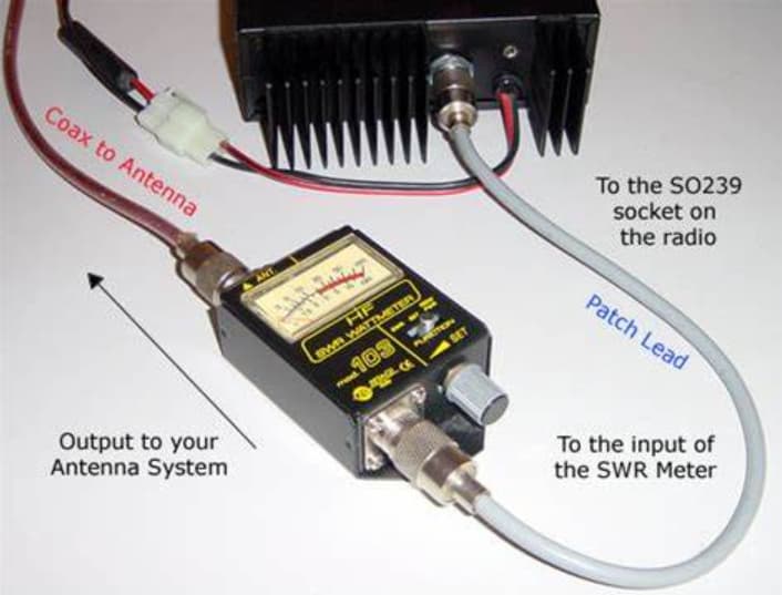
Figure 3: SWR Connecting Process
To begin, the antenna should be connected to the ANT (antenna) port on the meter. Next, use a patch lead to connect the transmitter to the TX (transmitter) port on the meter. If you're using an antenna tuning unit (ATU), it’s noteworthy to position the ATU close to the transmitter. This proximity enhances power efficiency and helps protect the system from environmental factors that could affect performance. While adding an ATU increases the overall cost, it significantly improves the ease of operation and overall system efficiency.
Placing the VSWR meter between the transmitter and the ATU is noteworthy for precise monitoring of VSWR levels, which is noteworthy to maintaining the health of the amplifier. Although the ATU can adjust the VSWR as seen by the transmitter, it doesn't change the inherent VSWR of the antenna itself. If the antenna isn’t properly matched, the VSWR can remain high, which can lead to inefficiencies. This setup ensures that you can accurately monitor and adjust performance, resulting in efficient transmission and reduced risk of damage to the transmitter components.
Preparing for SWR Meter Operation
Operating an SWR meter involves several significant steps, especially if you're new to using this equipment. First, it's notable to select a channel that is free from interference. This helps ensure accurate readings and prevents signal disruptions. To protect your equipment, reduce the transmitter's power output before starting, as a high SWR can potentially cause damage. For the most consistent and stable readings, set the transmitter to a fixed output mode, such as Continuous Wave (CW), Amplitude Modulation (AM), or Frequency Modulation (FM).
Start by setting the meter to measure forward power. Gradually adjust the calibration knob to ensure that the meter doesn't overload when the transmitter is active. Once you achieve a full-scale reading for forward power, switch the meter to measure reflected power. This will allow you to determine the VSWR. It's noteworthy to stop the transmission immediately after taking these readings to prevent interference and avoid overloading the transmitter.
To ensure your system is operating effectively across all frequencies, you should check the VSWR at each frequency you plan to use. Remember that VSWR can vary significantly across different frequencies, so this step is used for overall performance. If you decide to increase the transmitter's power output, make sure to recalibrate the meter to maintain accurate readings. This routine not only helps protect your transmitter but also optimizes the efficiency and reliability of your radio communication system.
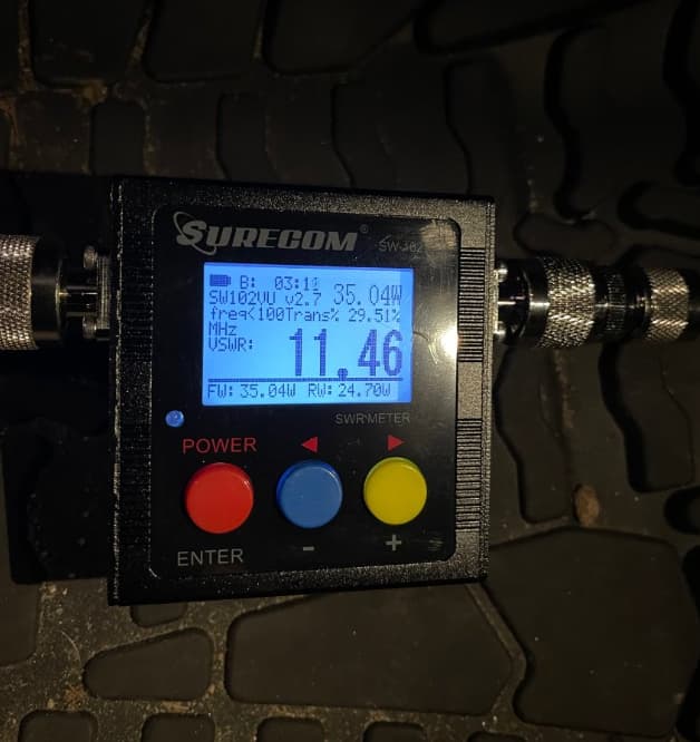
Figure 4: Poor SWR Readings
Identifying Poor SWR Readings
When you get a poor SWR (Standing Wave Ratio) reading, it usually means there's an issue with your transmission line setup. Specifically, it indicates that a significant amount of power is being reflected to the transmitter, which is often due to an impedance mismatch. Most VSWR meters provide a visual warning—usually marked in red—when the ratio exceeds 3:1. This alert is dominant as it warns you of the risk of damaging your transmitter due to excessive reflected energy.
Although there isn't a strict "pass" or "fail" standard for SWR readings, it's best to aim for a ratio as close to 1:1 as possible. A 1:1 reading means that nearly all the transmitted energy is reaching the antenna without being reflected, which minimizes energy loss and protects your equipment. By fine-tuning your transmission line to approach this ideal ratio, you can significantly enhance system efficiency and extend the lifespan of your radio components.
Optimal Locations for Measuring SWR
Balancing convenience with accuracy is a must when deciding where to measure SWR. The most straightforward spot is usually near the transmitter, which shows the SWR directly affecting your transmission equipment. However, this location might not provide an accurate picture of how the antenna is performing. The reason for this is feeder loss—the loss of signal strength along the transmission line—which can absorb some of the reflected power. As a result, a poor antenna match might appear acceptable when measured only at the transmitter end.
To get a more accurate reading of how well your antenna is performing, it’s a good idea to take SWR measurements at various points along the transmission line, especially closer to the antenna. By doing so, you can better detect and address any issues caused by feeder loss. This method ensures a more accurate reflection of the antenna’s efficiency and helps maintain the overall health of your radio frequency transmission system.
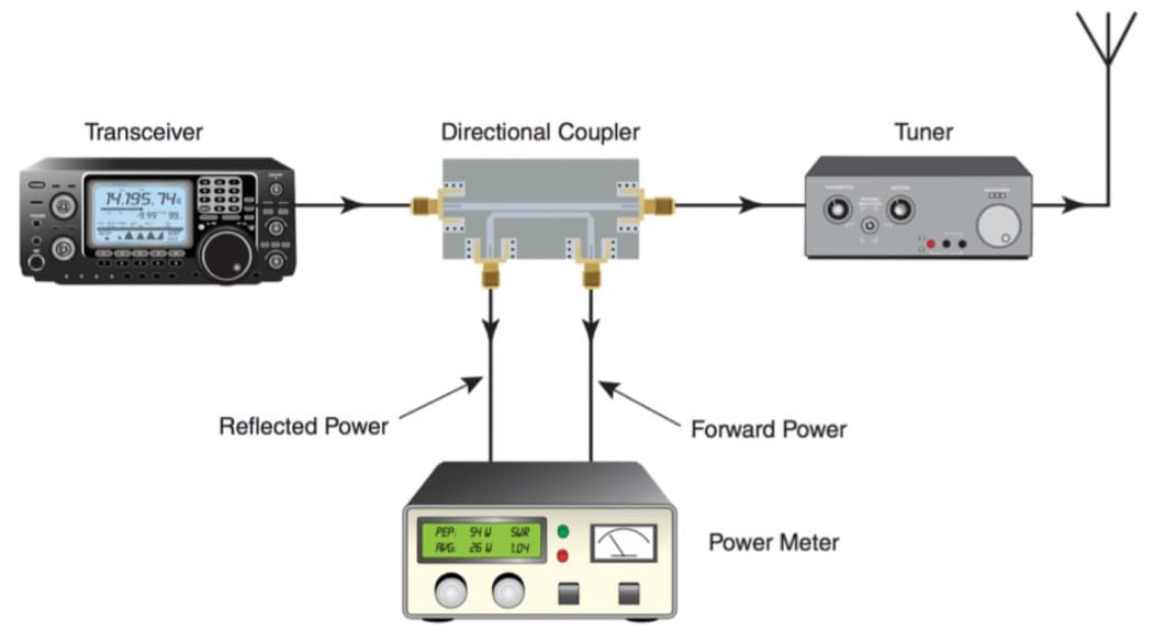
Figure 5: Directional SWR Meters
Mechanics of Directional SWR Meters
Directional SWR meters are equipped with internal transmission lines and directional couplers, allowing them to accurately measure both the transmitted and reflected wave amplitudes. Inside the meter, diodes convert these RF signals into DC voltages. Capacitors then smooth these voltages, stabilizing the signal to ensure accurate analysis.
This advanced setup is beneficial for precise impedance matching within the transmission line, which is substantial to maximizing transmission efficiency. By offering detailed insights into both the efficiency of the transmission and the overall health of the system, directional SWR meters play a significant role in diagnosing and improving radio communication performance.
With the ability to directly monitor and adjust key parameters, such as characteristic impedance, these meters help keep the system operating at its best. This not only minimizes energy loss but also reduces the risk of interference, ensuring that the communication system functions efficiently and reliably.
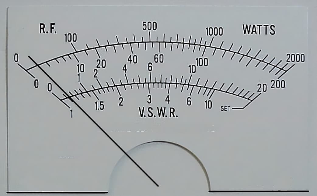
Figure 6: SWR Meter Reading
SWR Meter Reading Ranges
SWR (Standing Wave Ratio) readings are useful for evaluating the efficiency and health of your transmission system. The different ranges of these readings provide perilous information about the system's performance.
Ideal Range: 1.0 to 1.5 - Readings between 1.0 and 1.5 are ideal. They show that there is minimal RF energy being reflected and that energy transfer is happening efficiently. This range typically indicates that the antenna and transmission line are well-matched and properly aligned.
Acceptable Range: 1.5 to 1.9 - Readings from 1.5 to 1.9 are generally acceptable but might hint at minor issues. These could be due to slight mismatches in impedance or suboptimal antenna positioning. While not perfect, the system is still functioning fairly well, though it might benefit from some fine-tuning.
Problematic Range: 2.0 to 2.4 - If your readings fall between 2.0 and 2.4, this suggests more significant problems. These could be due to major installation errors, such as a poorly mounted antenna or incorrect feeder connections. In this range, immediate corrective actions are required to prevent further system degradation.
Grave Range: Above 2.5 - Readings above 2.5 indicate serious mismatches and inefficiencies in the system. At this level, there is a substantial risk of damaging the transmitter. Urgent intervention is desirable to correct these issues to avoid operational failures and costly repairs.
The SWR Formula Explained
The SWR is determined using the following formula:
![]()
Here, ![]() represents the reflection coefficient, which is the ratio of the reflected voltage
represents the reflection coefficient, which is the ratio of the reflected voltage ![]() to the forward voltage
to the forward voltage ![]() :
:
![]()
This formula is critical for diagnosing transmission efficiency and ensuring the overall health of the system. The value of ![]() directly reflects the degree of mismatch within the system. A higher
directly reflects the degree of mismatch within the system. A higher ![]() means more energy is being reflected, leading to a higher SWR. This indicates a greater mismatch, which reduces the system's efficiency.
means more energy is being reflected, leading to a higher SWR. This indicates a greater mismatch, which reduces the system's efficiency.
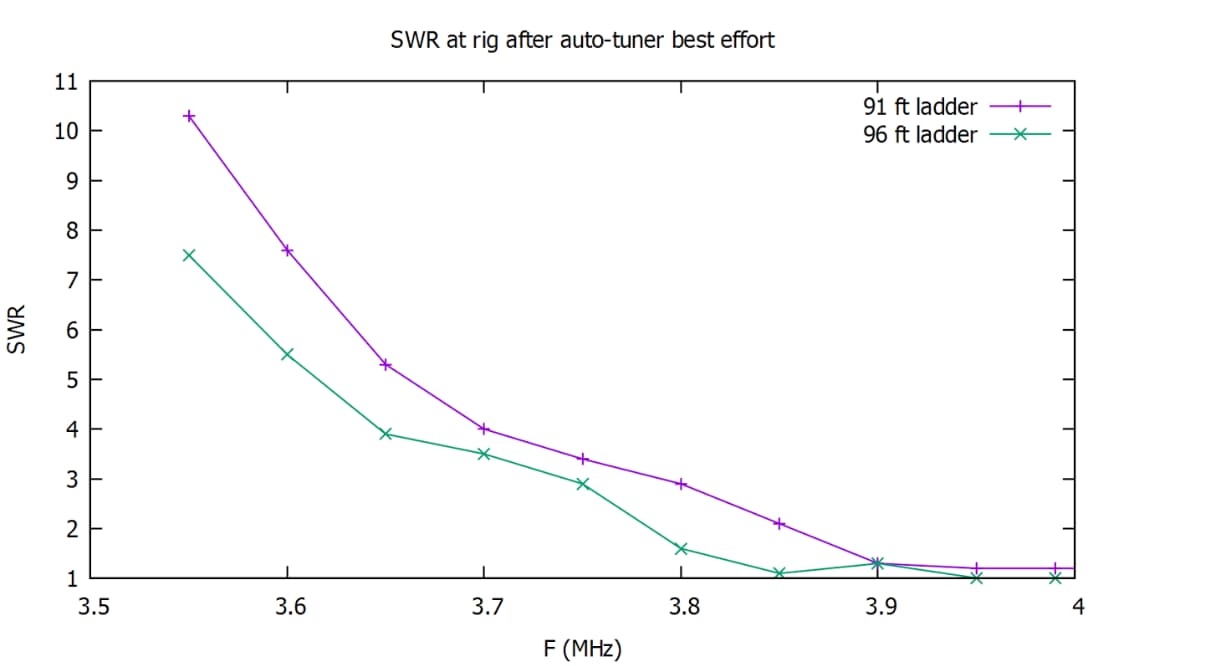
Figure 7: Ladder Line in High SWR
How does the Ladder Line Facilitate High SWR Operations?
The ladder line, known for its low-loss characteristics, offers significant advantages when dealing with high SWR situations. This type of transmission line, which includes both open wire and window line varieties, is particularly effective at high frequencies (HF). Unlike coaxial cables, a ladder line has much lower losses, making it an ideal choice for these scenarios.
One of the key benefits of a ladder line is its reduced attenuation. Even when SWR is high, the ladder line ensures that more of the reflected energy is re-radiated through the antenna, rather than being lost along the line. This efficiency is definite because it allows for better energy utilization, which directly improves the overall performance of the antenna system.
In high SWR environments, the use of a ladder line can significantly enhance the operational effectiveness of the system. By minimizing energy loss and ensuring that more power is efficiently radiated, the ladder line helps maintain optimal performance, even under challenging conditions.
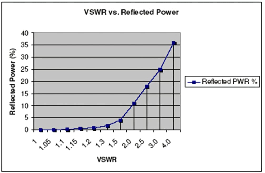
Figure 8: Standing Wave Ratio and Reflected Power
Comparing Standing Wave Ratio and Reflected Power
SWR (Standing Wave Ratio) measures the ratio of reflected power to forward power in a transmission system. When the SWR is high, it means that more power is being reflected along the transmission line, resulting in significant energy loss.
High SWR levels are concerning because they can cause various issues such as overheating, dielectric breakdown, and other harmful effects within the system. These problems arise from the excessive energy that is not being effectively transmitted and instead, is reflected, causing stress on the components. To avoid these risks, it's required to regularly monitor and adjust the SWR. Keeping the SWR within acceptable limits helps ensure that the transmission system operates efficiently and safely.
Conclusion
The meticulous study of SWR meters within the scope of radio communications underscores their significant role in maintaining and enhancing the efficiency and reliability of RF systems. From the initial setup and daily operations to addressing poor SWR readings and optimizing system performance, these meters provide invaluable insights into the health and functionality of radio transmission systems. As we have explored, achieving an ideal SWR reading is not merely a technical necessity but a practical one, directly impacting the longevity and effectiveness of the communication equipment.
In addition, the advanced capabilities of directional SWR meters and the benefits of utilizing ladder lines in high SWR scenarios reveal the depth of strategies available for managing and improving radio communication setups. Regular monitoring and accurate calculation of SWR are required practices that not only prevent equipment damage but also ensure that the system operates within its highest potential efficiency. Eventually, understanding and effectively using an SWR meter is not just about technical proficiency but about securing the integrity and future of radio communications. This in-depth examination provides both novices and seasoned professionals with the knowledge and tools needed to harness the full potential of SWR meters, thereby contributing to the sophisticated landscape of modern telecommunications.
Frequently Asked Questions [FAQ]
1. How do you perform a VSWR test?
To conduct a Voltage Standing Wave Ratio (VSWR) test, you’ll need a VSWR meter. Connect the meter between your transmitter and the antenna. Power on the transmitter to send a signal. The VSWR meter will display the ratio of the power that is transmitted versus the power that is reflected from the antenna. High VSWR indicates poor antenna efficiency due to impedance mismatch.
2. How do you read a digital SWR meter?
Reading a digital SWR (Standing Wave Ratio) meter involves observing the digital display which shows the VSWR value directly. Turn on your equipment and watch the display; it typically shows a number, for example, 1.5, which represents the VSWR value, indicating the ratio of forward to reflected power.
3. What is a good SWR reading?
A good SWR reading is typically between 1.0 and 1.5. This range indicates an efficient transmission system with minimal power being reflected to the transmitter. Readings below 2.0 are generally acceptable, but values above 2.0 suggest an inefficient system that may require adjustments to the antenna or the feedline.
4. What is a VSWR meter?
A VSWR meter is a device used to measure the Voltage Standing Wave Ratio in a transmission line. It evaluates how effectively a radio frequency (RF) signal is transmitted from a transmitter into a load (like an antenna), by measuring the power of the forward and reflected waves. This helps in assessing the match between the transmission line and the load.
5. What is the symbol for VSWR?
The symbol for VSWR is typically written as VSWR or sometimes as SWR. There isn't a specific graphical symbol; it is usually represented by these acronyms in texts and technical documents.