Exploring the Spectrum: A Guide to Modulation Methods
Why is modulation so important? Without it, sending low-frequency signals over long distances would require very large antennas, making global communication networks impractical. Modulation fixes this by shortening signal wavelengths, allowing long-distance transmission with smaller antennas. This advancement has shifted the industry from wired systems to more efficient, widespread, and strong communication networks.As the need for fast information and strong networks grows, understanding modulation methods becomes increasingly important. From analog to digital, each method improves transmission features like range, clarity, and bandwidth efficiency. This article will explore modulation's workings, benefits, uses, and complexities, highlighting its role as the foundation of modern communication, enabling global connectivity and information exchange.
Catalog
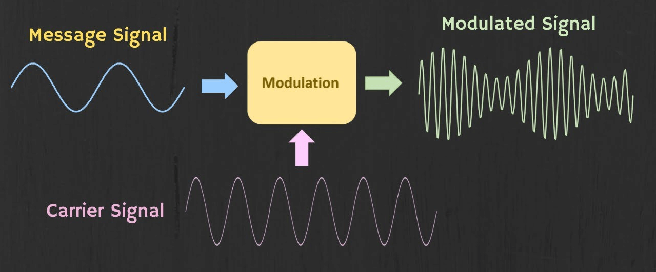
Figure 1: The Modulation
Types of Signals in the Modulation Process
Modulating Signal
The modulating signal, also known as the message signal, contains the information that needs to be transmitted. This is a low-frequency baseband signal. Its primary role is to carry the substantive content of the communication. Through modulation, this low-frequency signal is prepared for transmission over communication channels.
Carrier Signal
The carrier signal is a high-frequency signal with specific amplitude and phase properties. It does not carry any informational content by itself. Its main function is to transport the modulating signal from the source to the receiver. When combined with the modulating signal, the carrier signal allows for efficient data transmission across communication channels, overcoming transmission losses and noise.
Modulated Signal
The modulated signal is the outcome of combining the carrier and modulating signals. This signal takes on the high-frequency characteristics of the carrier while embedding the informational content of the modulating signal. Modulation can occur in different forms, such as amplitude, frequency, or phase modulation. Each technique modifies the modulated signal to optimize it for various transmission and reception conditions, ensuring efficient and reliable communication across distances and through different media.
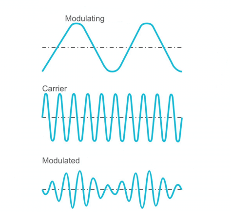
Figure 2 : The 3 Types of Signals in the Modulation Process
Modulation Methods
Analog Modulation
Analog modulation involves using a continuously varying wave as a carrier signal. This wave is adjusted to match the input message or data signal. The wave's amplitude, frequency, and phase can be modified for modulation. The main types of analog modulation are Amplitude Modulation (AM), Frequency Modulation (FM), and Phase Modulation (PM).
Amplitude Modulation (AM)
In Amplitude Modulation (AM), the carrier wave's amplitude is varied in direct proportion to the message signal. The frequency and phase of the carrier remain constant. This method produces a spectrum that includes a carrier frequency and lower and upper sidebands. AM requires more bandwidth and power than other modulation types and is more prone to noise and interference, making signal filtering challenging.
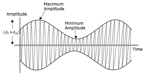
Figure 3: Amplitude Modulation
Frequency Modulation (FM)
Frequency Modulation (FM) changes the carrier wave's frequency based on the message signal's amplitude, while amplitude and phase remain stable. FM is superior to AM in suppressing noise but requires more bandwidth. It is widely used in radio broadcasting, radar systems, and telemetry.
FM parameters include the modulation index and maximum modulating frequency, which impact bandwidth and transmission efficiency. For example, wide-band FM (WBFM) has a large frequency deviation (±75 kHz) to provide high-quality audio in the 88.5–108 MHz range. While WBFM allows extensive data transmission, it requires about 200 kHz of bandwidth per channel.
Narrow-band FM (NBFM) has a low modulation index (β ≤ 0.3) and small frequency deviation, usually around ±3 kHz, making it ideal for less demanding uses. It uses much less bandwidth, about twice the modulating frequency.

Figure 4: Frequency Modulation (FM) Signal
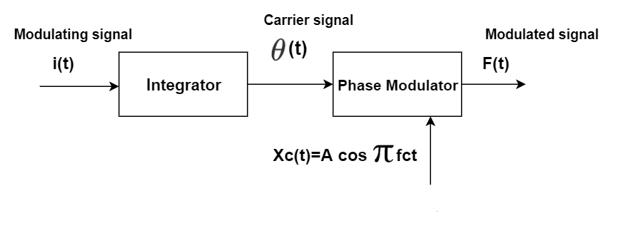
Figure 5: Frequency Modulation (FM) Block Diagram
Phase Modulation (PM)
Phase Modulation (PM) alters the carrier wave's phase in line with the data signal. Since phase changes affect frequency, PM is a type of frequency modulation. PM encodes data by shifting the phase angle of the carrier wave, different data values correspond to distinct phase shifts. For example, a '1' could be represented by a 0° shift and a '0' by a 180° shift.
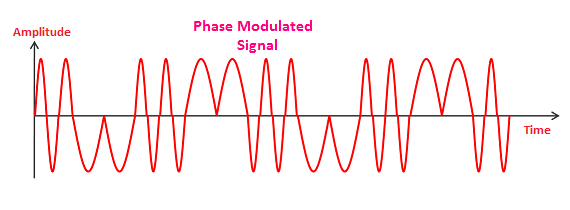
Figure 6: Phase Modulation (PM)
Digital Modulation
To achieve superior quality and efficient communication, digital modulation techniques are utilized. These methods offer clear advantages over analog modulation, such as better power efficiency, optimal use of available bandwidth and improved noise resistance. In digital modulation, the message signal is first converted from analog to digital format before being modulated with a carrier wave.
The carrier wave in digital modulation is manipulated by keying or switching it on and off to create pulses that carry the modulated signal. Digital modulation, like analog modulation, involves varying the amplitude, frequency, and phase of the carrier wave. This process falls into 5 main types.

Figure 7: Amplitude Shift Keying (ASK)
Amplitude Shift Keying (ASK)
Amplitude Shift Keying (ASK) changes the amplitude of a carrier signal based on digital input. This technique similar to analog amplitude modulation but for digital signals, represents binary 0 and 1 with different amplitude levels. ASK is commonly used in radio frequency (RF) transmissions. It sends data by switching the signal on and off, making it important for RF communication systems.
Frequency Shift Keying (FSK)
Frequency Shift Keying (FSK) encodes data by changing the carrier signal's frequency. This method is found in modems, cordless phones, and RFID systems. In Binary FSK, two distinct frequencies represent binary 0 and 1. Continuous-phase FSK, a variant, reduces abrupt phase changes for better signal stability. FSK switches between low and high frequencies to denote binary values, efficiently encoding digital information.

Figure 8: Frequency Shift Keying (FSK)
Phase Shift Keying (PSK)
Phase Shift Keying (PSK) encodes data by changing the carrier signal's phase. Binary PSK (BPSK) uses two phases separated by 180 degrees. Advanced versions like Quadrature PSK (QPSK) and Differential PSK (DPSK) encode multiple bits per symbol for higher efficiency. PSK involves precise timing to alter the phase of a constant frequency carrier wave. This technique, used in wireless LANs, RFID, and Bluetooth, is reliable due to its resistance to noise.
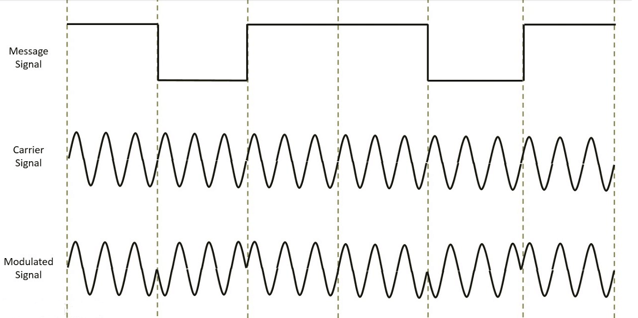
Figure 9: Phase Shift Keying (PSK)
Quadrature Amplitude Modulation (QAM)
Quadrature Amplitude Modulation (QAM) uses both amplitude and phase modulation to represent data efficiently. It is very efficient with spectrum and ideal for high-data-rate applications like digital TV and cable modems. Formats like 16-QAM, 64-QAM, and 256-QAM show different amplitude levels. QPSK, a QAM variant, modulates two bits at once, selecting from four phase shifts (0, 90, 180, 270 degrees), doubling the bandwidth's information capacity.

Figure 10: Quadrature Amplitude Modulation (QAM)
Orthogonal Frequency Division Multiplexing (OFDM)
Orthogonal Frequency Division Multiplexing (OFDM) is a digital multi-carrier modulation scheme. It uses many closely spaced orthogonal sub-carrier signals, each modulated with schemes like QAM. OFDM achieves high data rates and resists multi-path interference and fading. Used to modern broadband networks like LTE and Wi-Fi, OFDM efficiently transmits large data volumes over multiple closely spaced data streams.

Figure 11: Orthogonal Frequency Division Multiplexing (OFDM)
Pulse Modulation
Pulse modulation systems transmit information by modifying regular carrier pulses' amplitude, duration, timing, or shape. This method follows the "sampling principle," that ensures a continuous waveform with a limited spectrum can be precisely reconstructed from discrete samples taken at more than twice the signal's highest frequency. These samples modulate the carrier pulses. Pulse modulation is useful in telecommunications, control systems, and various electronic applications. The 6 main types of pulse modulation, with their technical details and applications, are:
Pulse Amplitude Modulation (PAM)
In PAM, the amplitude of the pulses is change according to the instantaneous samples of the message signal. This directly changes the pulse amplitude to match the signal's amplitude, while the pulse frequency and phase remain unchanged. PAM is a simple form of pulse modulation and is the basis for more advanced methods. It is widely used in Ethernet communication standards, transmitting digital data over wiring using voltage pulses. PAM facilitates efficient digital-to-analog conversion, supporting high-speed data transmission in networking environments.
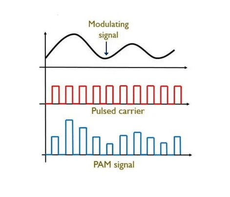
Figure 12: Pulse Amplitude Modulation (PAM)
Pulse Width Modulation (PWM)
PWM changes the width (duration) of the pulses based on the modulating signal, while keeping the amplitude and frequency constant. This technique is effective for controlling power delivered to devices like motors and lights, making it common in industrial automation and consumer electronics. For example, PWM adjusts motor speed by changing the pulse width, directly influencing the motor’s power. It is also used to dim LED lights by varying the duty cycle, adjusting brightness without changing the light color.

Figure 13: Pulse Width Modulation (PWM)
Pulse Position Modulation (PPM)
In PPM, the position of each pulse changes according to the modulating signal's amplitude with fixed pulse width and amplitude. PPM provides better immunity to amplitude noise compared to PAM and PWM, making it suitable for optical communication systems like fiber optics, where timing precision required. PPM’s resistance to noise improves the reliability of data transmission over long distances, ensuring high fidelity in optical networks.
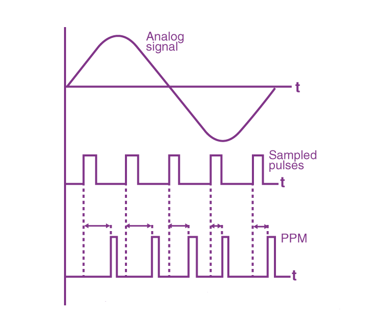
Figure 14: Pulse Position Modulation (PPM)
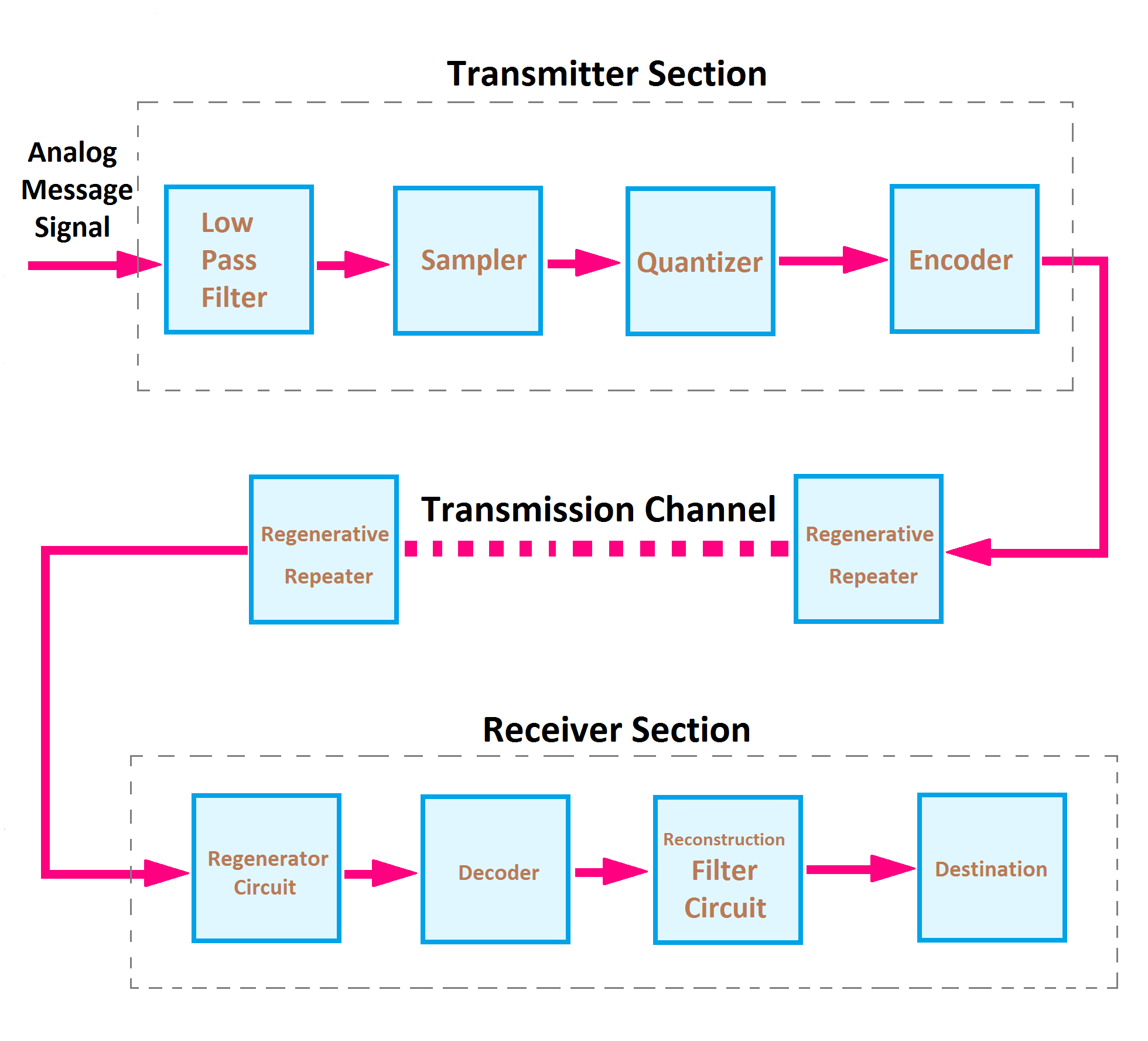
Figure 15: Pulse Code Modulation (PCM)
Pulse Code Modulation (PCM)
PCM is a digital method for transmitting analog data. The analog signal is sampled at regular intervals, quantized, and encoded into digital bits. PCM is the standard for digital sound in computers, telephony, and other digital audio applications. It offers a reliable way to transmit analog audio signals digitally with high fidelity. Each analog sample is represented by a fixed number of bits, ensuring consistency and precision in digital audio processing. PCM’s widespread use in digital telephony and audio recording highlights its importance in modern communication systems.
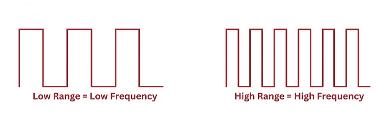
Figure 16: Pulse Density Modulation (PDM)
Pulse Density Modulation (PDM)
Also known as Pulse Frequency Modulation (PFM), PDM changes the pulse density based on the analog signal amplitude. In audio applications, microphones use PDM to convert analog sound into a digital signal. PDM’s advantage lies in its simplicity for integrated circuits and making the design of digital-to-analog converters easier. This method is useful for portable audio devices. PDM's ability to represent high-fidelity audio signals with minimal hardware complexity makes it a preferred choice in consumer electronics.

Figure 17: Differential Pulse Code Modulation (DPCM)
Differential Pulse Code Modulation (DPCM)
DPCM is a variant of PCM where the difference between successive samples is encoded, reducing the bit rate compared to standard PCM. This method is useful in situations with limited bandwidth because it reduces data transmission without losing much quality. DPCM exploits the correlation between successive samples in audio and video signals, effectively compressing data for efficient transmission. Its application in video compression standards, such as MPEG, demonstrates DPCM’s ability to enhance data transmission efficiency while maintaining acceptable quality levels.
Spread Spectrum
Spread spectrum is a modulation technique used to protect message signals from interference, environmental noise, and jamming. It ensures secure communication and makes signal detection difficult. The main types of spread spectrum techniques are Frequency Hopping Spread Spectrum (FHSS), Direct Sequence Spread Spectrum (DSSS), Time Hopping Spread Spectrum (THSS), and Chirp Spread Spectrum (CSS).
Frequency Hopping Spread Spectrum (FHSS)
In Frequency Hopping Spread Spectrum (FHSS), the signal is sent over various radio frequencies, changing from one frequency to another at set intervals. The hopping sequence and timing need to be known and synchronized between the transmitter and receiver. This technique is highly resistant to jamming and interception, making it ideal for military communications. It is also used in Bluetooth and some wireless local area networks (WLANs). The frequent frequency changes make it hard for adversaries to predict the next frequency, enhancing resistance to interference.
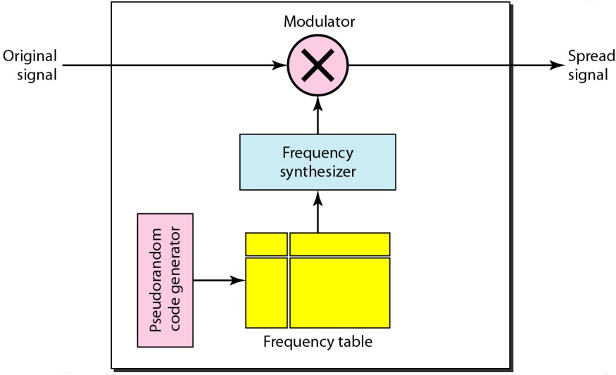
Figure 18: Frequency Hopping Spread Spectrum (FHSS)
Direct Sequence Spread Spectrum (DSSS)
Direct Sequence Spread Spectrum (DSSS) spreads the original data signal over a wider frequency bandwidth by multiplying it with a pseudo-random noise spreading code. This code has a higher bandwidth than the data, resulting in the data being distributed across a broader range of frequencies. DSSS improves resistance to interference and jamming. It is used in wireless communication systems, including GPS and the original IEEE 802.11 Wi-Fi standards. The main advantage of DSSS is its ability to improve the signal-to-noise ratio (SNR) and making the signal less prone to noise and other interferences.
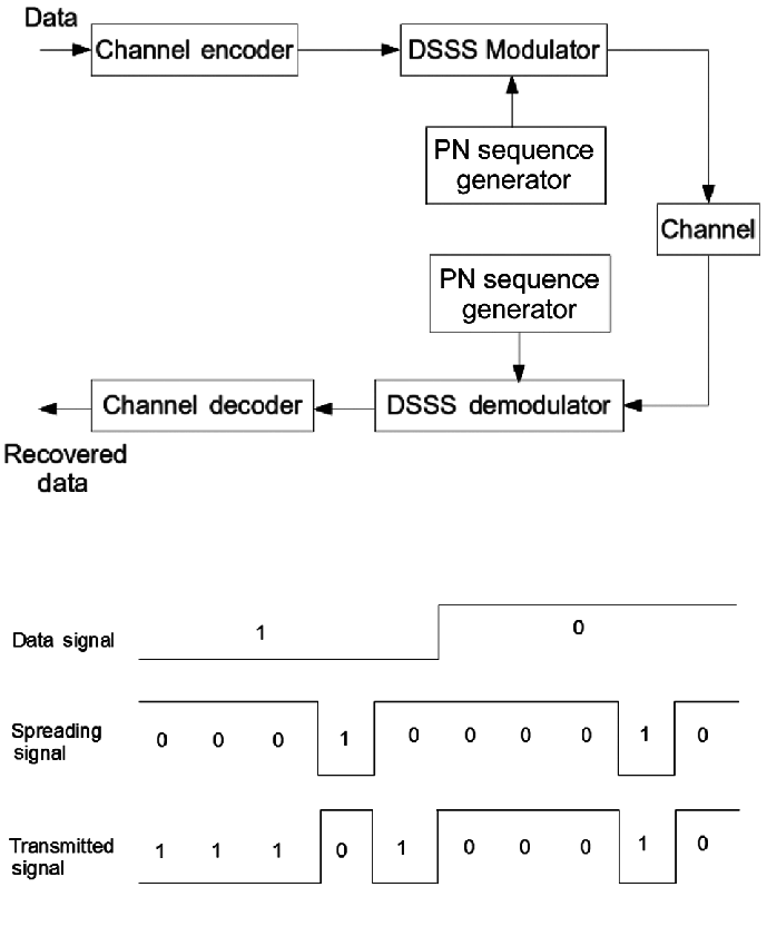
Figure 19: Direct Sequence Spread Spectrum (DSSS)
Time Hopping Spread Spectrum (THSS)
Time Hopping Spread Spectrum (THSS) transmits data in short bursts at different time intervals, determined by a pseudorandom sequence known to both the transmitter and receiver. Although less common, THSS can be used in ultra-wideband (UWB) systems and secure communication systems. This method adds a time-based element to signal spreading, enhancing security and making it more resistant to interference and interception.
Chirp Spread Spectrum (CSS)
Chirp Spread Spectrum (CSS) changes the frequency of a signal over time in a linear or exponential way, producing a "chirp" sound. This method is good at handling multipath interference and allows long-range communication with low power use. CSS is used in radar and in long-range, low-power communication systems like LoRa technology, popular in Internet of Things (IoT) devices. The frequency change in CSS enables precise timing and distance measurement, making it useful for applications needing high accuracy and reliability.

Figure 20: Chirp Spread Spectrum (CSS)
Advantages of Modulation
Reduced Antenna Size: Modulation allows for the use of smaller antennas by shifting the transmitted signal to a higher frequency range. At these higher frequencies, smaller antennas can operate effectively.
Prevention of Signal Interference: Modulation techniques help minimize signal interference and ensuring that different signals do not merge. This leads to clearer and more reliable communication.
Extended Communication Range: By using modulation, signals can be transmitted and received over longer distances. This enhances the effectiveness of long-distance communication.
Multiplexing Capability: Modulation allows for multiple signals to be sent simultaneously over a single communication channel. This optimizes the use of available bandwidth.
Adjustable Bandwidth: Different modulation schemes enable adjustments in bandwidth based on specific requirements. This provides greater flexibility and efficiency in communication systems.
Improved Reception Quality: Modulation reduces noise and interference, resulting in clearer and more reliable received signals.
Disadvantages of Modulation
Higher Equipment Costs: Implementing modulation requires sophisticated and often expensive equipment. These costs include both procurement and maintenance.
Complexity of Receiver and Transmitter Designs: Modulated systems require more complex transmitter and receiver designs, leading to greater technical challenges and maintenance demands.
Proximity Requirement for FM Systems: In Frequency Modulation (FM) systems, antennas need to be positioned relatively close to each other to maintain optimal performance.
Inefficiency for Large Bandwidths: Certain modulation techniques are not suitable for applications that require large bandwidths, limiting their effectiveness in these scenarios.
Increased Power Consumption: Modulation can increase power use, which is a big problem for power-sensitive applications.
Applications of Various Types of Modulation
Modulation techniques are important because they change signal properties to make information transmission more efficient. Here are some uses:
Music Mixing and Magnetic Tape Recording
In music production and magnetic tape recording, modulation adjusts the amplitude or frequency of audio signals. This ensures high-fidelity sound reproduction and minimizes noise. Techniques like amplitude modulation (AM) and frequency modulation (FM) blend different audio tracks, creating a seamless and cohesive sound experience.
EEG Monitoring for Newborns
Modulation is important in medical applications, especially for monitoring newborn brain activity. Electroencephalography (EEG) uses frequency modulation to track and record brain waves. This allows precise detection of neurological conditions, aiding early diagnosis and treatment. Modulating and demodulating these signals ensure accurate readings and reliable data collection.
Telemetry Systems
Telemetry systems depend on modulation to transmit data over long distances. Phase modulation (PM) and frequency modulation (FM) encode information onto carrier signals, enabling real-time monitoring of remote systems. In the automotive and aerospace industries, real-time telemetry is good for monitoring component performance and condition.
Radar Systems
Frequency modulation improves the accuracy and resolution of detected signals. This enables precise measurement of distance, speed, and direction of objects, best for air traffic control and weather forecasting.
FM Broadcasting
In broadcasting, frequency modulation (FM) is used for high-quality audio transmission. FM broadcasting provides better sound quality and less interference than amplitude modulation (AM). By modulating the frequency of the carrier wave, it encodes audio information, delivering clear and reliable sound to listeners.
Conclusion
Modulation helps to improve our communication skills. By studying different techniques, from traditional analog to advanced digital and pulse methods, we learn their benefits and applications. Techniques like Frequency Modulation (FM) and Phase Modulation (PM) are used for high-quality, low-noise uses, such as FM broadcasting and radar. Digital methods like QAM and OFDM are used for high-data-rate services like digital TV and broadband internet. However, modulation also brings challenges like higher equipment costs, complex designs, and increased power use. As we keep innovating, modulation remains central to making information transmission more efficient, reliable, and secure worldwide.
Frequently Asked Questions [FAQ]
1. What is the best modulation technique?
The best modulation technique depends largely on the application requirements such as bandwidth efficiency, power efficiency, complexity, and the specific communication environment. For example, in environments where bandwidth is limited but power is not, phase modulation (PM) might be ideal due to its resilience against noise and interference. On the other hand, for applications needing high data rate transmission, orthogonal frequency-division multiplexing (OFDM) is often preferred, as it efficiently uses the available spectrum and is less susceptible to multi-path interference.
2. Which modulation technique is least expensive?
Amplitude modulation (AM) is generally considered the least expensive and simplest form of modulation. It requires less complex and cheaper equipment, making it suitable for consumer-grade electronics and broadcast applications. However, it is less efficient in terms of bandwidth usage and more vulnerable to noise compared to other techniques like frequency modulation (FM) or digital modulation schemes.
3. How to determine modulation type?
To determine the appropriate modulation type, one must consider several factors:
Bandwidth Requirements: How much spectrum is available for the communication?
Power Constraints: Is the transmitter power limited?
Environmental Factors: Are there issues with multipath interference or a noisy channel?
System Requirements: What are the data rate needs and error rate tolerances?
The decision involves a trade-off among these factors, influenced by the specific needs of the communication system.
4. Why over modulation is avoided?
Over modulation in systems like AM and FM leads to signal distortion and bandwidth spillage, causing interference with adjacent channels. This not only degrades the quality of the communication but also violates regulatory limits on bandwidth usage. In digital systems, over modulation can lead to symbol clipping and increased error rates. Maintaining modulation levels within specified limits is required for efficient and compliant operation.
5. What is poor modulation?
Poor modulation refers to a scenario where the modulation process does not optimally use the allocated bandwidth or results in a high error rate. Symptoms of poor modulation include higher power usage, more frequent transmission errors, and interference with other signals. It typically results from inadequate system tuning or using a modulation technique that does not align well with the operational conditions and system requirements.
6. What is the formula for modulation?
The formula for modulation depends on the type of modulation used. For example:
Amplitude Modulation (AM): m(t) = (1 + k ⋅ x (t) ⋅ c(t)
where k is the modulation index, x(t) is the message signal, and c(t) is the carrier signal.
Frequency Modulation (FM): y(t) = A ⋅ sin (ωct + kf ∫ x (t) dt)
where A is the amplitude, ωc is the carrier frequency, kf is the frequency deviation constant, and x(t) is the message signal.
Each type of modulation will have its specific parameters that influence how the formula is applied based on the operational requirements and objectives of the communication system.