Exploring DIAC Functionality in Various Application Circuits
In modern electronics, precise control and reliable switching are fundamental to the functionality of numerous devices and systems. One major component that plays a significant role in achieving these objectives is the DIAC or DIODE for Alternating Current. A member of the Thyristor family, the DIAC is a bidirectional semiconductor switch that facilitates the controlled triggering of TRIACs and other Thyristor-based circuits. This article explores the operational principles, construction, and practical applications of DIACs, highlighting their importance in various electronic circuits. By understanding the DIAC's unique characteristics, such as its symmetrical switching and bidirectional conduction, engineers can enhance the performance and efficiency of circuits used in motor speed controls, light dimmers, heater controls, and more. The following sections provide a comprehensive overview of the DIAC's function, design, construction, and application, emphasizing its role in ensuring smooth and reliable operation in AC control systems.Catalog

Figure 1: DIAC or DIODE for Alternating Current
DIAC Overview
The DIAC, or DIODE for Alternating Current, is a bidirectional semiconductor switch that conducts electrical current in both directions. It belongs to the Thyristor family and is primarily used to trigger TRIACs and other Thyristor-based circuits. A DIAC starts to conduct when the voltage applied across it exceeds its break-over voltage. DIACs come in various packages, such as discrete components with small leaded packages, surface-mount packages, and larger packages that can be bolted to a chassis. For convenience, DIACs and TRIACs are often integrated into single packages.
To guarantee that the TRIAC is activated in a regulated and efficient manner, a DIAC is needed. This is especially imperative for applications like heater controls, motor speed controls, and light dimmers. The DIAC remains non-conductive until the AC voltage rises and exceeds the break-over voltage. At this point, the DIAC quickly transitions from a non-conductive to a conductive state, triggering the TRIAC and allowing current to flow. This rapid switching action provides a clean switching characteristic and reduces harmonic distortion.
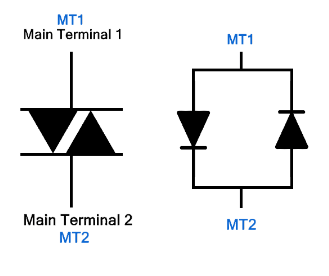
Figure 2: DIAC Symbol
DIAC Symbol
The DIAC symbol consists of two diodes connected in parallel but oriented in opposite directions, reflecting its bidirectional nature. This symbol is key for understanding its operation and integrating it into designs. The DIAC has two terminals, usually labeled A1 and A2 or MT1 and MT2 (where MT stands for Main Terminals). These terminals are reversible, similar to those of a resistor or ceramic capacitor, simplifying circuit design as orientation during installation is not a concern.
Unlike other Thyristors, DIACs do not have a controlling gate terminal. This means they switch states based solely on the voltage level across their terminals. When the voltage exceeds the DIAC's break-over voltage, it begins conducting current in either direction.
Understanding the DIAC symbol and its function is dynamic for circuit designers. For example, when integrating a DIAC into a TRIAC triggering circuit, the break-over voltage characteristic must be considered. The break-over voltage determines when the DIAC will switch from non-conductive to conductive, thereby triggering the TRIAC. Before implementing the DIAC, engineers frequently simulate circuit behavior under various voltage circumstances to confirm its functionality.
When installing the DIAC, practitioners ensure the component is correctly placed on the PCB (Printed Circuit Board), paying attention to the terminals. Although the DIAC's bidirectional nature makes orientation less dangerous, maintaining a consistent assembly process aids in troubleshooting and verification. Proper soldering techniques are used to avoid cold joints that could affect the DIAC's performance.
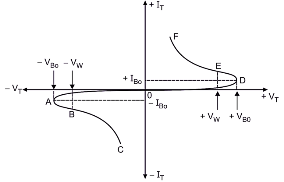
Figure 3: DIAC Construction
How a DIAC is Constructed?
The DIAC's construction is similar to a transistor but with key differences designed for bidirectional conduction. Unlike transistors, DIACs do not have a base terminal, relying solely on the voltage across their terminals to start conduction.
A typical DIAC has a symmetrical five-layer structure made of alternating positive (P) and negative (N) doped semiconductor materials. The outer layers, near the terminals, are heavily doped for strong electrical contact and low resistance. This symmetrical doping ensures that the DIAC switches identically for both polarities of applied voltage, providing consistent performance regardless of current direction.
The five-layer structure can be visualized as PNPNP or NPNPN, depending on the design and manufacturer. When AC voltage is applied, one of the outermost layers becomes forward-biased, while the opposite becomes reverse-biased, depending on the voltage's polarity. As the voltage reaches the break-over point, the middle layers undergo avalanche breakdown, causing the DIAC to become conductive and allow current flow.
The DIAC's construction supports repetitive switching without significant wear, making it reliable for applications needing frequent on-off cycles, like light dimmers. During manufacturing, precise control over doping levels and layer thicknesses ensures the DIAC operates within its specified break-over voltage range, providing consistent performance over its lifespan.
Understanding the DIAC's internal structure aids technicians and engineers in diagnosing circuit issues. For instance, if a DIAC does not conduct at the expected voltage, it may indicate a defect or damage to one of the internal layers. Measuring the voltage drop across the DIAC and comparing it to the specified break-over voltage can help assess its condition.
When integrating a DIAC into a circuit, proper thermal management is insistent. Excessive heat can degrade the semiconductor layers, leading to premature failure. Ensuring adequate heat dissipation through proper mounting and using heat sinks or thermal pads is a must-have for maintaining the DIAC's reliability.
The Working Principle of DIAC
The DIAC operates based on its symmetrical structure and the activation of its layers depending on the applied voltage polarity. Understanding this principle is settling for effectively using DIACs in AC control applications.
|
|
Positive MT1 Relative to MT2
|
Positive MT2 Relative to MT1
|
|
Description |
The P1 layer near MT1 becomes forward-biased, initiating conduction through the sequence P1-N2-P2-N3 |
The P2 layer near MT2 becomes forward-biased, initiating conduction through the sequence P2-N2-P1-N1.
|
|
The junctions P1-N2 and P2-N3 are forward-biased, allowing current to pass through them |
The junctions P2-N2 and P1-N1 are forward-biased, facilitating current flow.
|
|
|
The N2-P2 junction remains reverse-biased until the voltage reaches the DIAC's break-over voltage, causing avalanche breakdown and enabling current flow.
|
The N2-P1 junction remains reverse-biased until the voltage exceeds the break-over threshold, triggering avalanche breakdown and allowing current flow.
|
Chart 1: DIAC’S Working Principle
For AC applications, in which the voltage polarity alternates regularly, bidirectional conduction is needed. The DIAC switches between conductive and non-conductive states based on the applied voltage, ensuring symmetrical operation in both directions.
Monitoring the voltage levels across the DIAC ensures proper triggering. For example, in a phase control dimmer, the DIAC must trigger the TRIAC at precise points in the AC cycle to achieve smooth dimming. Adjustments to circuit components, like timing capacitors and resistors, can fine-tune the triggering points.
During assembly and testing, ensure the DIAC's correct placement and secure connections are vibrant. Any loose connections or incorrect orientation, although less dangerous due to bidirectionality, can lead to inconsistent triggering and circuit performance issues. Technicians often use oscilloscopes to observe the waveform and verify that the DIAC triggers at the correct voltage levels, ensuring reliable operation.
Figure 4: VI Characteristics of DIAC
DIAC VI Characteristics
The VI characteristic curve of a DIAC is distinctive, showing a 'Z' shape that highlights its bidirectional conduction capability. This curve is plotted across the first and third quadrants, representing the positive and negative polarities of the applied voltage.
First Quadrant (Positive Half-Cycle)
When MT1 is positive relative to MT2, the DIAC starts in a high-resistance state with minimal leakage current, known as the blocking state. As the voltage increases to the DIAC's breakdown voltage, the internal junctions undergo avalanche breakdown, causing the resistance to drop sharply and transitioning the DIAC from non-conductive to conductive. Consequently, the current flow increases significantly, and the voltage across the DIAC decreases abruptly, marking the start of conduction from MT1 to MT2.
Third Quadrant (Negative Half-Cycle)
When MT2 is positive relative to MT1, the DIAC begins in a high-resistance blocking state with minimal leakage current. Upon reaching the negative breakdown voltage, the junctions undergo avalanche breakdown, sharply dropping the resistance and transitioning to a conductive state. Consequently, the current flow increases, and the voltage across the DIAC decreases, allowing conduction from MT2 to MT1.
How to Effectively Use a DIAC?
DIACs are requisite in TRIAC circuits to address non-symmetrical firing issues, which can produce unwanted harmonics and reduce circuit efficiency. Here’s a detailed guide on using a DIAC, emphasizing practical application and operational nuances.
Figure 5: Circuit Design
Circuit Design
When integrating a DIAC with a TRIAC, position the DIAC in series with the gate terminal of the TRIAC to enable symmetric triggering during both the positive and negative halves of the AC cycle. In addition, select a DIAC that has a break-over voltage aligning with the TRIAC’s firing requirements to guarantee that the DIAC triggers the TRIAC at the appropriate voltage, thus ensuring consistent symmetrical operation.
Symmetrical Switching
When AC voltage is applied, the DIAC remains non-conductive until the voltage exceeds its break-over threshold. Upon reaching this threshold, the DIAC becomes conductive, allowing current to flow to the TRIAC's gate. This configuration ensures that the TRIAC receives gate current only at the necessary threshold, which prevents premature or asymmetrical firing. As a result, the TRIAC fires evenly in both the positive and negative cycles, minimizing harmonic distortion and maintaining the stability of the system.
Troubleshooting
Inconsistent Firing: If the TRIAC does not fire symmetrically, check the DIAC's operation. Measure the voltage across the DIAC to ensure it matches the specified break-over voltage. Replace the DIAC if it shows signs of wear or damage.
Harmonic Distortion: If unwanted harmonics are present, confirm that the DIAC is correctly positioned and that the TRIAC gate is receiving consistent triggering signals. Adjust component values as necessary to fine-tune firing points.
Key Specifications of DIAC
Selecting a DIAC requires understanding its key performance parameters:
• Breakover Voltage (VBO)
This is the voltage at which the DIAC switches from non-conductive to conductive. It must be high enough to prevent unintended activation but low enough for reliable operation. Choose VBO based on application needs for safety and reliability.
• Breakover Current (IBO)
This is the minimum current needed for the DIAC to start conducting. Select a value that balances sensitivity and robustness to ensure effective triggering without false trips or premature failures.
• On-state Voltage (VTO)
This is the voltage drop across the DIAC when it is conducting. A low VTO minimizes power loss and indicates efficiency during conduction.
• On-state Current (IT)
This specifies the maximum current the DIAC can handle without overheating or damage. Ensure the DIAC's IT rating matches the application to prevent thermal overload and ensure longevity.
• Power Dissipation (PD)
This is the maximum power the DIAC can dissipate safely while conducting. To avoid extreme temperatures, which can impair performance and dependability, effective heat management is required.
• Operating Junction Temperature Range
This range defines the thermal limits within which the DIAC can operate reliably. Performance can degrade significantly outside this range due to changes in electrical properties and increased thermal stress.
• Breakover Voltage Symmetry
For reliable operation in AC applications, symmetry in the breakover voltage is needed. Ensure good symmetry to prevent waveform distortions and maintain efficient and reliable circuit operation.
DIAC Firing Voltage Levels: What You Need to Know?
The firing voltage, or breakdown voltage, for a DIAC typically ranges from 28V to 42V. This threshold voltage is major for precise control in various applications. Here's a detailed look at its significance and operational nuances:
The specific voltage at which the DIAC switches from non-conductive to conductive is requisite for ensuring accurate control. This voltage can be found in the DIAC's datasheet and should match the application's requirements for optimal performance.
The DIAC also needs a trigger current, typically around 200 µA (0.2 mA), to start conducting. For dependable and effective circuit performance, the trigger current in the DIAC must be set correctly. Selecting a DIAC with the appropriate firing voltage and trigger current is key to achieving dependable performance in circuit designs.
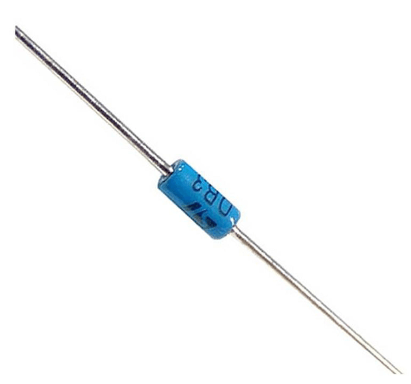
Figure 6: DB3 DIAC
Detailed Specifications of DB3 DIAC
The DB3 DIAC is widely used for its robust performance parameters. Here’s a detailed breakdown of its key specifications:
• Breakover Voltage Range
The DB3 DIAC operates within a break-over voltage range of 28-36V. This range makes it suitable for medium-voltage applications, ensuring precise control over the switching point and optimizing circuit stability and responsiveness.
• Maximum Breakover Current
The maximum breakover current is 50µA. This low current threshold allows for sensitive triggering, enhancing efficiency in critical applications.
• Maximum Rise Time
The rise time for the DB3 DIAC is limited to 2µs. For devices that need to respond quickly, such as motor speed controllers and lighting dimmers, this fast switching capacity is significant.
• Operating Junction Temperature Range
The DIAC operates efficiently within a temperature range of -40°C to +125°C. This wide range demonstrates the DIAC's adaptability to various environments, maintaining consistent performance under extreme conditions.
• Repetitive Peak On-State Current
The DB3 DIAC can handle a repetitive peak on-state current of 2A at a frequency of 120Hz. This capability indicates its strength in withstanding high currents during repetitive operations, making it ideal for applications involving frequent switching cycles.
Implementing DIAC in an LED Blinking Circuit
A common application of a DIAC, such as the DB3, DB4, or NTE6408, is in an LED blinking circuit. This circuit effectively demonstrates how DIACs control power delivery in practical applications.
AC to DC Conversion
Diode Rectification: Two 1N4007 diodes convert alternating current (AC) into direct current (DC).
Capacitor Charging: A 47µF capacitor charges with the rectified DC until the voltage across it reaches the DIAC's breakdown voltage.
Figure 7: AC to DC Conversion
DIAC Conduction and LED Activation
Once the voltage hits the DIAC's breakdown threshold, the DIAC conducts. The conducting DIAC triggers the LED to turn on.
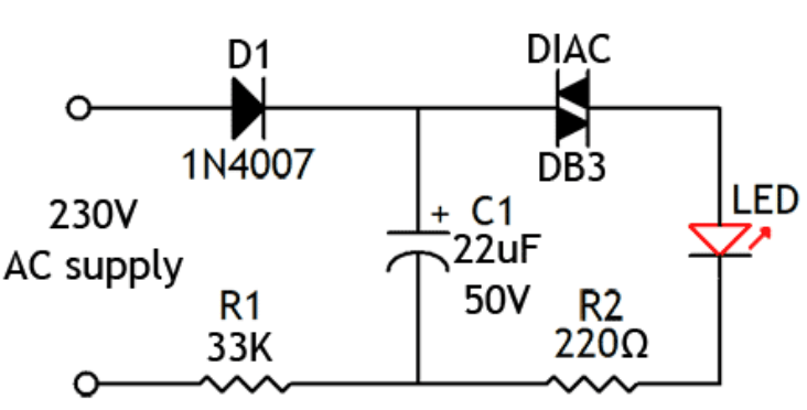
Figure 8: LED Activation
Controlling the Blinking Rate
The blink rate of the LED can be controlled by changing the capacitor's value. Increasing capacitance extends the charge time, slowing the blink rate. Decreasing capacitance shortens the charge time, quickening the blink rate.
Pros and Cons of DIAC
Pros
Symmetrical Switching Characteristics: The DIAC provides symmetrical switching, which minimizes harmonic distortion in AC circuits. This improves waveform integrity and overall application efficiency.
Low On-State Voltage Drop: In its conducting state, the DIAC has a low voltage drop, enhancing energy efficiency. This reduces conduction power loss, which matters for high-efficiency applications.
Ease of Triggering: The DIAC can be switched on easily by a small voltage adjustment. This allows for simple and responsive control in various circuit designs.
Smooth Power Control: When used with other thyristors and TRIACs, the DIAC enables smooth power control. This is beneficial for applications needing gradual power changes, like light dimmers and motor speed controllers.
Cons
Limited Power Capability: The DIAC is a low-power device. Its limited power handling restricts its use to smaller, less power-intensive applications, often requiring additional components for high-power tasks.
Conduction Threshold: The DIAC typically does not conduct below approximately 30 volts. This limits its utility in low-voltage applications and must be considered during design to ensure compatibility.
Inability to Block High Voltages: The DIAC cannot block high voltages. This makes it unsuitable for applications requiring high voltage isolation, necessitating alternative solutions or additional protective components.
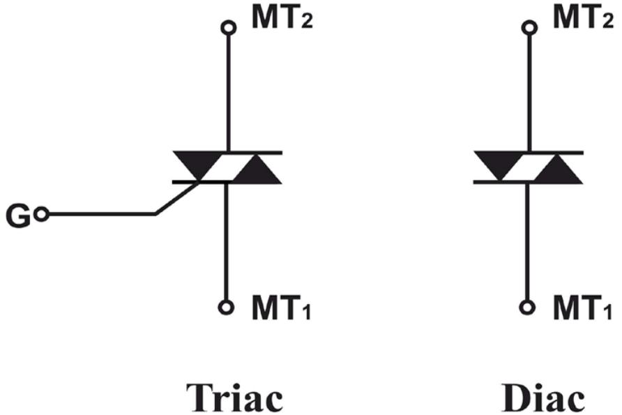
Figure 9: Difference Between DIAC & TRIAC
12. DIAC vs. TRIAC: The Differences
|
Construction and Operation
|
DIAC
|
TRIAC
|
|
A DIAC has two terminals and acts as a bidirectional switch without a gate terminal.
|
A TRIAC has three terminals: a gate and two main terminals.
|
|
|
It conducts current only after its breakover voltage is reached in either direction, making it simple but limited in control flexibility. |
It conducts current only after its breakover voltage is reached in either direction, making it simple but limited in control flexibility.
|
|
|
Application and Performance |
Typically used with TRIACs to stabilize the firing angle across both halves of the AC cycle.
|
Enhanced by DIACs for consistent switching characteristics.
|
|
Minimizes harmonic distortions and non-symmetrical firing, which makes sense for applications like motor speed controllers and light dimmers.
|
Suitable for applications requiring precise control and can handle various load types.
|
|
|
Power Handling and Control |
Low-power device is suitable for triggering mechanisms.
|
Can control significant power levels and is versatile in handling various load types.
|
|
Cannot directly manage large currents or voltages.
|
Ideal for robust applications requiring direct control of high voltages and currents, such as industrial motor controllers and household appliances. |
|
|
Protection and Reliability
|
Limited protection features |
Can be equipped with single-fuse protection, enhancing reliability against overload conditions |
|
Suitable for safety-critical applications and adaptable for a broad range of electrical uses.
|
Chart 2: DIAC vs. TRIAC: The Differences
Common Applications of DIACs
DIACs are primarily used to trigger TRIACs or other Thyristors in applications requiring symmetrical activation. They are needed for temperature modulation systems, light dimmers, and motor speed regulation in phase control circuits. Below are specific applications with detailed explanations.
Heat Control
An LC network with a capacitor (C1) and a choke (L) moderates voltage escalation across the TRIAC when it is non-conductive. A potentiometer (R2) adjusts the voltage across both halves of the AC cycle. A resistor (R4) connected across the DIAC ensures smooth control. The TRIAC's conduction period correlates directly with the heat generated by the heating element.
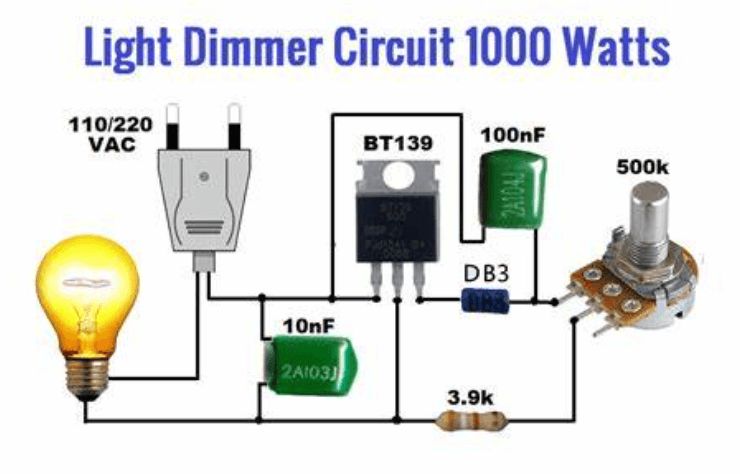
Figure 10: Light Dimmer
Light Dimmer
A DIAC works with an RC phase-shift network to manage TRIAC operation. The RC configuration modulates the TRIAC gate voltage. When the capacitor (C3) voltage exceeds the DIAC's breakdown threshold, the DIAC conducts, discharging C3 and triggering the TRIAC's gate. Adjusting the resistance changes the TRIAC's firing angle, regulating light intensity.
Proximity Detector Circuit
An SCR is in series with the load. A programmable unijunction transistor (PUT) connects to a detection probe. Increased capacitance from nearby presence triggers the PUT, which then triggers the SCR, activating the load.
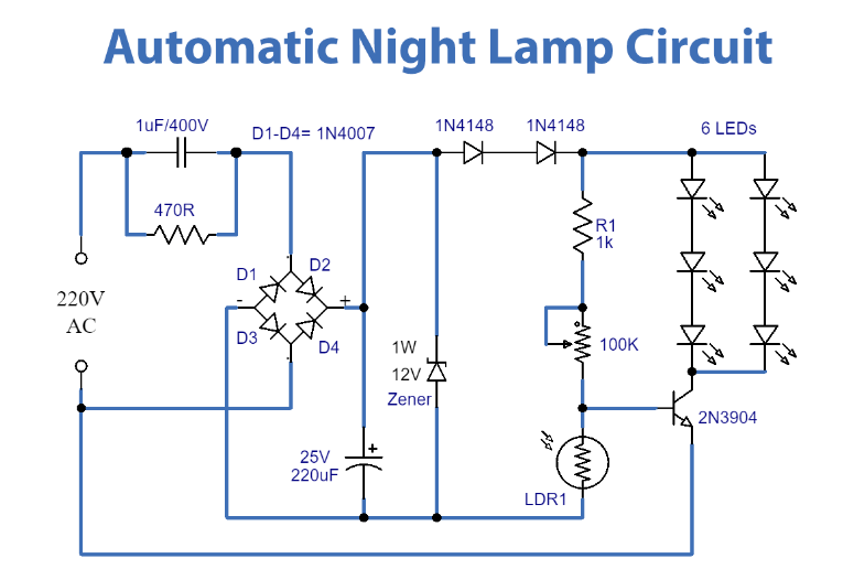
Figure 11: Automatic Night Lamp Circuit
Automatic Night Lamp
This circuit uses an LDR, TRIAC, and DIAC as ambient light decreases, the voltage at the DIAC junction rises. When the DIAC and TRIAC trigger, the lamp illuminates. Increased light reduces voltage, turning the lamp off.
Amplitude Triggered Switch
Uses a DIAC to actuate a switch based on input voltage amplitude. When voltage exceeds a set threshold, the DIAC conducts, activating the load. Ideal for creating amplitude-sensitive switching mechanisms.
Electronic DC Switch
Maintains a DIAC near its conduction threshold with stable voltage. A slight voltage increase causes the DIAC to conduct until the voltage returns to zero.
Electrically Latched Relay
The DIAC is non-conductive under stable voltage. The increased voltage causes the DIAC to conduct, latching the relay until the signal stops.
Latching Sensor Circuit
Once triggered by a sensor, the DIAC conducts. The circuit remains triggered until manually reset.
DC Overload Circuit Breaker
Disengages a load when the supply voltage exceeds a set level. The DIAC activates upon detecting excess voltage, triggering a transistor and relay to cut the load connection.
AC Overload Circuit Breaker
Uses capacitors and a diode rectifier for AC voltages. Protects AC power systems.
Phase-Controlled Triggering Switch
Employs a DIAC to adjust the firing angle of a TRIAC. Needed for situations where customized phase pulse outputs are required.
Conclusion
The DIAC's ability to conduct electrical current in both directions upon reaching a specific voltage threshold makes it an indispensable component in AC control applications. Its symmetrical switching properties ensure minimal harmonic distortion, which is key for maintaining waveform integrity and overall circuit efficiency. The detailed examination of the DIAC's construction reveals a sophisticated five-layer structure designed for bidirectional conduction, while its VI characteristics demonstrate the distinct operational phases essential for precise control.
Practical applications of DIACs, from light dimmers to motor speed controllers, underscore their versatility and effectiveness in managing power delivery in a variety of settings. By integrating DIACs with TRIACs, engineers can achieve controlled and adjustable power output, enhancing the performance and reliability of electronic devices. Understanding the nuances of DIAC operation, from installation to troubleshooting, enables the development of robust and efficient electronic circuits, ensuring that these components remain major in the advancement of modern electronics technology.
Frequently Asked Questions [FAQ]
1. What is a DIAC in circuits?
A DIAC (Diode for Alternating Current) is a semiconductor device that can conduct electrical current only after its breakover voltage has been reached, regardless of the polarity of the applied voltage. This means it is a bidirectional device, allowing current flow in both directions once triggered.
2. Where would you use a DIAC?
DIACs are commonly used in applications involving phase control and triggering for TRIACs (another type of bidirectional semiconductor device). They are typically found in light dimmers, speed controls for electric motors, and other AC switching applications. DIACs help in providing a stable trigger pulse to the TRIAC, ensuring reliable operation.
3. Why is a DIAC important?
A DIAC is important because it provides a precise triggering mechanism for devices like TRIACs. By ensuring a consistent and stable trigger pulse, DIACs help in achieving smooth and controllable switching of AC loads. This makes them decisive for applications where precise control of power is needed, such as in light dimming and motor speed control.
4. What is an example of a DIAC?
A common example of a DIAC is the DB3, which is widely used in electronic circuits for triggering TRIACs. The DB3 has a typical breakover voltage of around 30V. When the voltage across the DIAC reaches this level, it switches to a low-resistance state, allowing current to flow and triggering the connected TRIAC.
5. What type of switch is a DIAC?
A DIAC is a type of bidirectional trigger switch. Unlike a traditional switch that you manually operate, a DIAC operates automatically based on the voltage applied across it. Once the voltage exceeds its breakover threshold, the DIAC switches from a high-resistance state to a low-resistance state, allowing current to pass through. This automatic triggering characteristic makes it useful for precise control applications in AC circuits.