Distinguishing Between Ohmic and Non-Ohmic Materials in Electrical Engineering
In electrical engineering, a distinction is made between electrically conductive materials and ohmic and non-ohmic types. Ohmic conductors comply with Ohm's Law, displaying a linear relationship between voltage and current, indicating constant resistance under different electrical loads. This predictable nature is dynamic for designing and operating electronic devices and circuits.On the other hand, non-ohmic conductors show variable resistance, complicating their use but providing benefits in advanced applications like power regulation and signal processing. Their behavior varies with changes in temperature, material properties, and electrical loads, necessitating detailed analysis to maximize their utility. This exploration of ohmic and non-ohmic conductors highlights their distinctive characteristics, applications, and analytical methods needed to optimize electronic component design and functionality.
Catalog
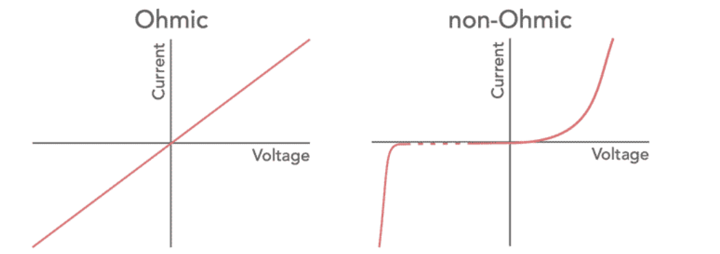
Figure 1. Ohmic and Non-Ohmic Conductors
Understanding Ohmic and Non-Ohmic Conductors
When examining how voltage and current interact in different types of conductors, we rely on a tool called the V-I characteristic curve. This curve plots voltage on the y-axis and current on the x-axis. To create this curve, the voltage applied across the conductor is gradually adjusted while the resulting current is measured. This process reveals how the conductor responds to various voltage levels.
In ohmic conductors, the relationship between voltage and current is straightforward and predictable. According to Ohm's law, these two quantities are directly proportional. As the voltage increases, the current increases at a steady rate, producing a straight-line (linear) V-I curve. This linearity indicates that the resistance within the conductor remains constant, regardless of how much the voltage changes. Earlier assumptions that materials might exhibit non-linear behavior under these conditions have proven incorrect for ohmic conductors.
Non-ohmic conductors, however, do not follow this simple pattern. At lower voltages, they may initially exhibit a linear relationship similar to ohmic conductors. But as the voltage continues to rise, the curve starts to bend or deviate from the straight line, indicating that the resistance is no longer constant. Instead, it varies depending on the voltage applied. This non-linear behavior is commonly seen in devices such as incandescent light bulbs and certain semiconductor components. In these cases, factors like temperature changes and material properties under different electrical conditions contribute to the shifting resistance.
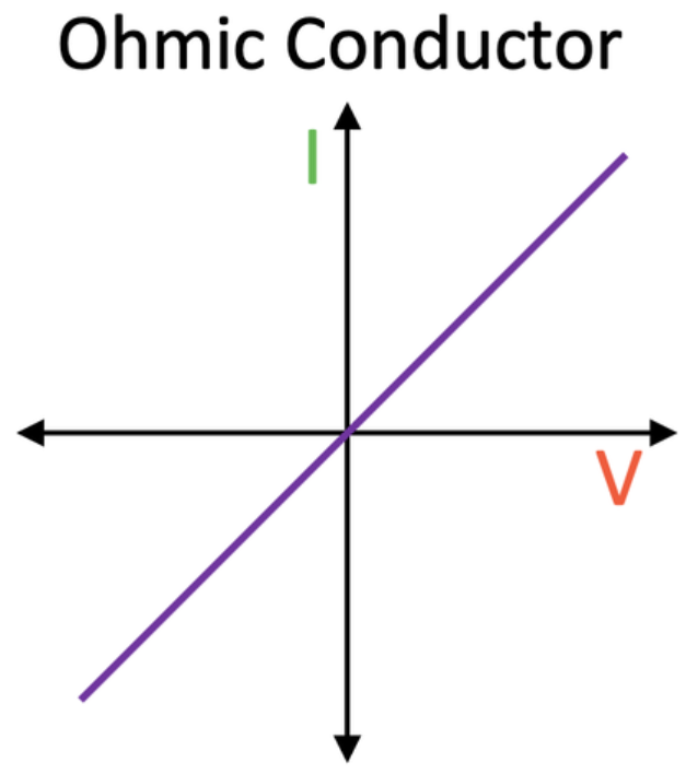
Figure 2: Ohmic Conductors
Role of Ohmic Conductors in Electronics
Ohmic conductors are defined by their adherence to Ohm's Law, which states that the current flowing through a conductor is directly proportional to the voltage across it. Simply put, if you double the voltage applied to an ohmic conductor, the current will also double. This behavior is predictable and is represented mathematically as V=IR where R is the resistance. In ohmic conductors, R remains constant regardless of changes in voltage or current.
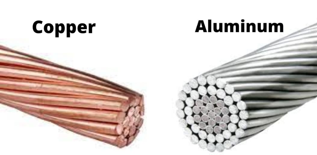
Figure 3: Examples of Materials with Ohmic Properties
Common examples of materials with ohmic properties include metals like copper and aluminum, as well as carbon and certain metal alloys. These materials are known for their stable resistance, which ensures a reliable relationship between voltage and current. When this relationship is graphed on a V-I curve, the result is a straight line. The slope of this line represents the resistance of the conductor—if the line is steep, the resistance is high; if it’s shallow, the resistance is low. This linear relationship is influential in the design and functioning of electronic circuits. For instance, copper wires are extensively used in electrical systems because of their low resistance, which remains stable across different operating conditions. This stability is dynamic for maintaining consistent circuit performance and avoiding issues like overheating or voltage drops.
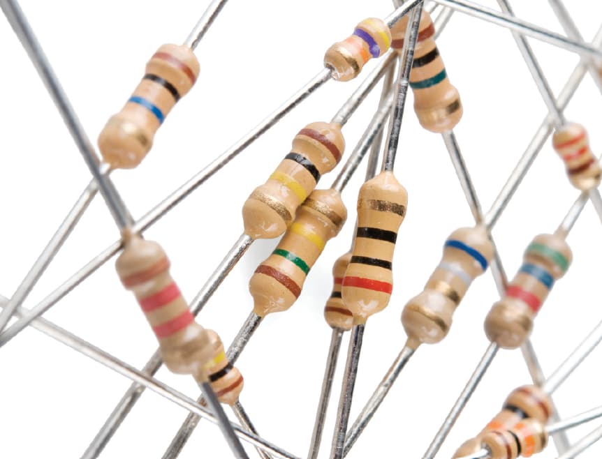
Figure 4: Resistors
Resistors, which are suitable components for controlling voltage and current within circuits, typically exhibit ohmic behavior. They are designed to provide a specific amount of resistance to regulate the flow of electricity, ensuring that circuits function as intended. In most applications, the predictability of ohmic resistors is highly desirable. However, there are situations where non-ohmic resistors are preferred, such as in surge protection devices, where the resistance needs to change in response to different electrical conditions. The reliability and predictable nature of ohmic conductors and components form the backbone of most electronic devices. Their ability to maintain consistent performance under varying conditions makes them requisite in a wide range of applications, from simple wiring to complex circuit designs.
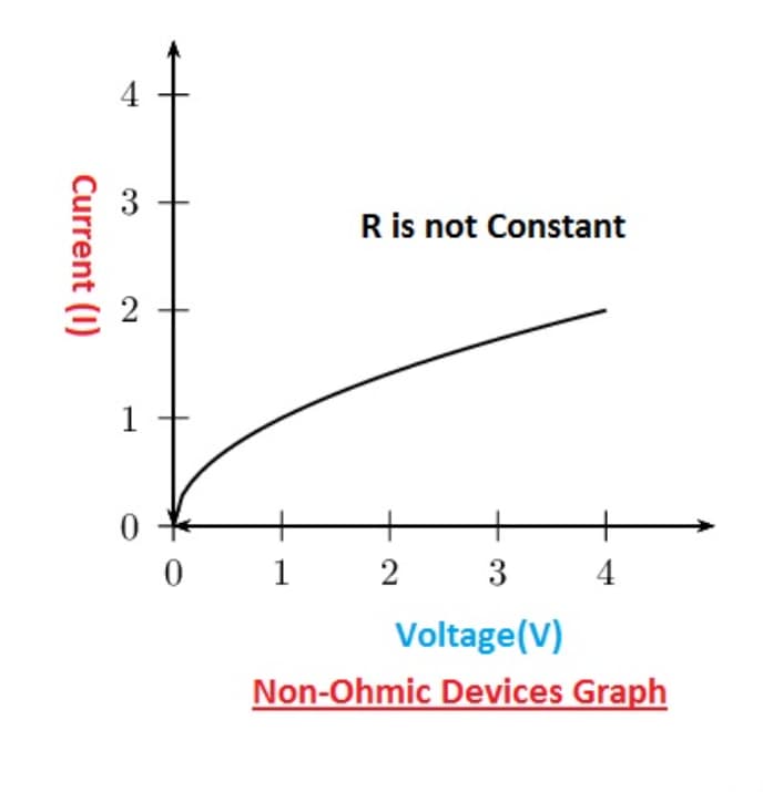
Figure 5: Non-Ohmic Conductors
Advanced Applications of Non-Ohmic Conductors in Electronic
Non-ohmic conductors are characterized by resistance that changes with applied voltage, making their behavior more complex compared to ohmic conductors. Unlike ohmic conductors, where current and voltage are directly proportional, non-ohmic conductors do not follow Ohm's Law. For example, in an incandescent light bulb, the filament's resistance increases as it heats up, altering the current flow. This means that if the voltage is doubled, the current does not simply double because the resistance changes with temperature and material properties.
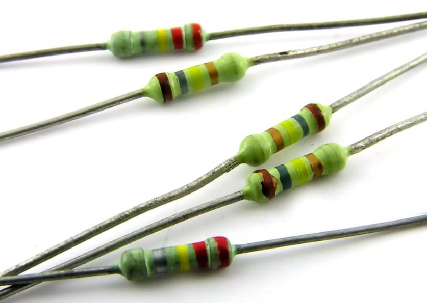
Figure 6: Semiconductor Diodes
Semiconductor diodes offer another example of non-ohmic behavior, where current flows predominantly in one direction. The voltage-current (V-I) relationship for a diode is highly non-linear. A diode will not allow significant current to flow until the applied voltage exceeds a certain threshold, known as the forward voltage. Below this threshold, the current remains very low. On the other hand, when voltage is applied in the reverse direction, the current stays minimal until a grave breakdown voltage is reached. This unique behavior is settling for the process of rectification, where alternating current (AC) is converted to direct current (DC).

Figure 7: Incandescent Bulbs
The variable resistance and non-linear response of components like diodes and incandescent bulbs highlight the intricate relationship between voltage, resistance, and current in non-ohmic conductors. These properties are used for more advanced electronic applications but also introduce challenges in terms of predictability and circuit design. Engineers must carefully consider these factors when integrating non-ohmic components into electronic systems to ensure proper functionality and reliability.
Comparative Analysis of Ohmic and Non-Ohmic Conductors
Ohmic conductors are easily identified by their straightforward, linear relationship between current and voltage. When plotted on a graph, this relationship forms a straight line, indicating that the resistance remains constant regardless of the voltage applied. This consistent behavior is unaffected by changes in temperature or other operational conditions. Materials like copper, commonly used in wiring, and standard electronic components such as resistors, exemplify ohmic conductors. Their stable and predictable electrical characteristics are insistent in ensuring reliable circuit performance across various environmental conditions.
Non-ohmic conductors behave differently, displaying a nonlinear relationship between voltage and current. In these materials, resistance changes with factors such as temperature and electrical load, leading to a V-I curve that bends or curves rather than forming a straight line. This indicates that the resistance is not constant but varies depending on the operating conditions. Examples of non-ohmic conductors include semiconductor devices like diodes and transistors, which are dynamic in modern electronics. Electrolytes used in batteries and electrochemical cells also fall into this category. These components are useful in applications where controlled changes in resistance and current flow are desirable, such as in power regulation and signal processing.
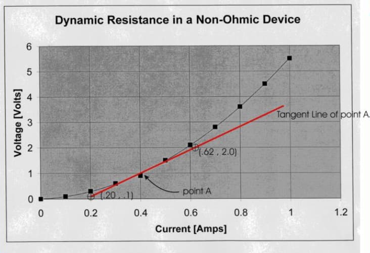
Figure 8: Resistance of a Non-Ohmic Conductor
Methods for Assessing Resistance in Non-Ohmic Conductors
To find the resistance of non-ohmic conductors, you need to use the slope method, which calculates the differential resistance at specific points along the voltage-current (V-I) curve. This method involves selecting two points on the curve and calculating the ratio of the change in voltage(∆V) to the change in current (∆V). The slope of the line between these two points gives the resistance at that particular part of the curve.
Unlike ohmic conductors, which have a constant resistance, non-ohmic conductors show resistance that varies with changes in voltage and current. This makes the slope method needed because it provides a localized measurement of resistance, reflecting how the conductor behaves at different operational states.
Dynamics of Resistance in Non-Ohmic Conductors
|
Dynamics of Resistance in Non-Ohmic
Conductors |
|
|
Complex Variables in Resistance
Calculation |
Calculating resistance in non-ohmic
conductors involves a mix of factors like material properties, temperature
fluctuations, electric field intensity, and doping levels in semiconductors.
These elements interact to shape the conductor’s resistance in ways that can
be quite intricate. |
|
Material Properties and Resistance |
The composition of a conductor plays a
main role in determining its resistance. In semiconductors, for example,
adding different atoms (a process known as doping) alters how electrons move
through the material. These electrons often collide with atoms, and the
nature of these atoms—what they are and how they’re arranged—affects the ease
with which electrons can flow. The more difficult it is for electrons to
move, the higher the resistance. |
|
Temperature Effects |
Temperature changes have a significant
impact on the resistance of non-ohmic conductors. As the temperature rises,
the atoms in the conductor vibrate more intensely, increasing the chances of
electrons colliding with them. This increased collision rate leads to higher
resistance. This temperature sensitivity is a Furthermore characteristic of
non-ohmic conductors, especially in environments where temperatures
fluctuate. |
|
Electric Field Intensity |
In semiconductors, the strength of the
electric field can also influence resistance. A strong electric field can
generate more charge carriers—electrons and holes—which reduces resistance.
This principle is particularly significant in devices like varistors, which
protect sensitive electronics by diverting excess voltage during power
surges. |
|
Doping and Its Effects |
Doping involves adding impurities to a
semiconductor to modify its electrical properties. By increasing the number
of charge carriers, doping typically lowers resistance. The ability to
precisely control doping levels allows for fine-tuning the behavior of
semiconductors, ensuring that electronic devices perform optimally under a
variety of conditions. |
Conclusion
The exploration of ohmic and non-ohmic conductors reveals an intense dichotomy in the realm of electrical conductance. Ohmic conductors, with their steadfast and predictable nature, continue to underpin the stability and efficiency of traditional electrical circuits and devices. Their consistent resistance provides a cornerstone for basic circuit design principles and the broader reliability of electrical infrastructures. Similarly, non-ohmic conductors, with their dynamic resistance characteristics, play a key role in the advancement of electronic technology, especially in devices requiring nuanced control of electrical properties under varying operational states. The ability to precisely measure and manipulate the resistance of these conductors, especially through techniques like the slope method, enhances our capacity to design circuits that are both innovative and adaptable to changing conditions.
As we further our understanding of these materials through detailed analysis and practical applications, the distinctions between ohmic and non-ohmic behaviors not only enrich our theoretical knowledge but also guide the development of more sophisticated and reliable electronic systems. Thus, the study of these conductors is not merely academic but an insistent endeavor in the evolution of electronic engineering and technology.
Frequently Asked Questions [FAQ]
1. What are 3 non ohmic conductors?
Semiconductors: Materials like silicon and germanium, do not follow Ohm's law over a wide range of voltages and temperatures due to their unique band structures.
Diodes: Specifically designed to allow current to flow in one direction only, displaying different resistances based on the direction of the applied voltage.
Transistors: These devices, used extensively in electronic circuits, exhibit varying resistance based on input voltage and signal, which does not align with Ohm’s Law.
2. What is an example of an ohmic device?
Metal Wire Resistor: A resistor made from metals like copper or nichrome follows Ohm's Law very closely, exhibiting a linear relationship between voltage and current under constant temperature conditions.
3. What are the characteristics of a non-ohmic conductor?
Voltage-Dependent Resistance: The resistance changes with the applied voltage, not maintaining a constant ratio.
Directional Dependency: In devices like diodes, resistance can vary based on the direction of the applied current.
Temperature Sensitivity: Many non-ohmic materials show significant changes in resistance with temperature changes.
4. What is the difference between non-ohmic and ohmic conductors?
Resistance Behavior: Ohmic conductors have a constant resistance over a range of voltages and temperatures, adhering to the formula V=IRV = IRV=IR. Non-ohmic conductors do not have a constant resistance and their V−IV-IV−I relationship is not linear.
Linearity: Ohmic conductors display a linear relationship between current and voltage. Non-ohmic conductors exhibit a nonlinear relationship, where the plot of current versus voltage curves or bends.
5. What are the two examples of non-ohmic resistance?
Light Emitting Diodes (LEDs): Their resistance changes with the voltage applied and only allows current to pass above a certain threshold voltage.
Varistors (Voltage Dependent Resistors): Components that change their resistance with the voltage applied across them, commonly used for protecting circuits against high voltage spikes.