BNC Connector: Design, Types, and Applications
The BNC coax connector is a main part of radio frequency (RF) systems, valued for its simplicity and reliability. It's popular because it's easy to use and works well, making it a common choice in devices like oscilloscopes, audio generators, power meters, and function generators. Another feature is its bayonet locking mechanism that keep the connection secure and prevents it from loosening due to small movements that could affect signal quality. The BNC connector also maintains consistent impedance, reducing signal loss and reflection. The article takes a close look at different types of BNC connectors, designs, ways to assemble and compares them with other connectors.Catalog
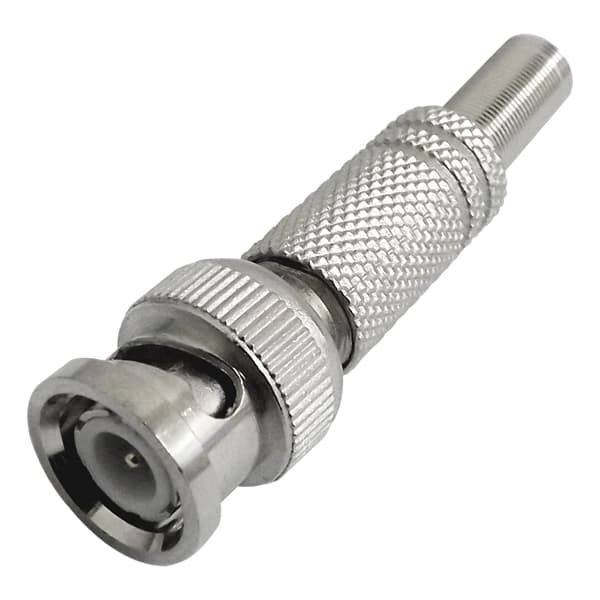
Figure 1: BNC Connector
The BNC Development
The BNC (Bayonet Neill-Concelman) connector was created in the late 1940s to solve a problem in electronics as devices became smaller. Before the BNC, larger connectors like the N-type and C-type were common but they were becoming too big for modern needs.
The name "BNC" comes from its design and its inventors. The "B" stands for "bayonet," referring to the twist-and-lock mechanism that makes it easy to connect and disconnect without special tools. The "N" and "C" stand for Paul Neill and Carl Concelman, the engineers who helped develop it.
The BNC connector was made to keep up with the rapid changes in technology after World War II, especially in communication and broadcasting. Its durability and ease of use made it popular in many fields, including telecommunications and aerospace.
Over the years, the BNC connector has been updated to match advances in technology. Though it was first made for the military, it later became common in commercial and consumer electronics too. Although newer connectors have been developed, the BNC is still used for strong, high-frequency connections, showing its lasting value in both military and consumer electronics.
Types of BNC Connectors
Standard 50 Ohm and 75 Ohm BNC Connectors
You can think of these like different types of roads, each one is built for different speeds and traffic conditions. The 50 ohm connector is like a high-speed freeway, handling faster data signals and higher frequencies (up to 4 GHz, or even 10 GHz). The 75 ohm version is more like a regular city road, often used for things like TV cables and slower data signals.
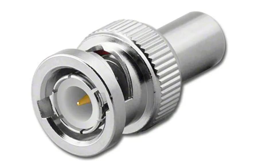
Figure 2: 50 Ohm BNC Connector
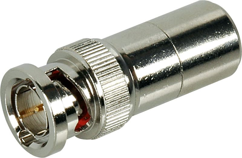
Figure 3: 75 Ohm BNC Connector
High Voltage BNC Connectors
These connectors are made to handle up to 500 volts. They are used in industries where high voltage signals are common, such as scientific labs and industrial settings.
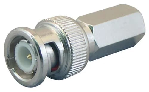
Figure 4: High Voltage BNC Connector
Corrosion-Resistant BNC Connectors
Made with materials that can resist rust and damage from moisture, these connectors are good for use in wet or corrosive environments. They’re often made from stainless steel or nickel to last longer.
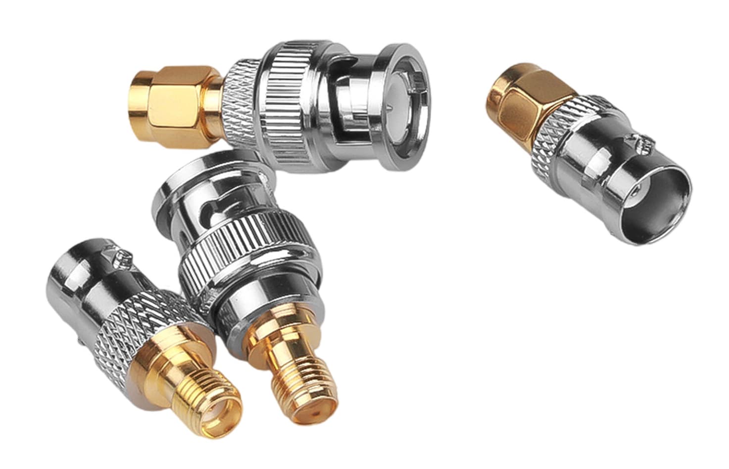
Figure 5: Corrosion-Resistant BNC Connector
Miniature and Micro BNC Connectors
As devices become smaller, there’s a need for smaller connectors. Miniature (MBNC) and Micro (µBNC) connectors work like standard BNCs but are much smaller. These are used in small electronics and mobile devices, especially in telecommunications and aerospace.
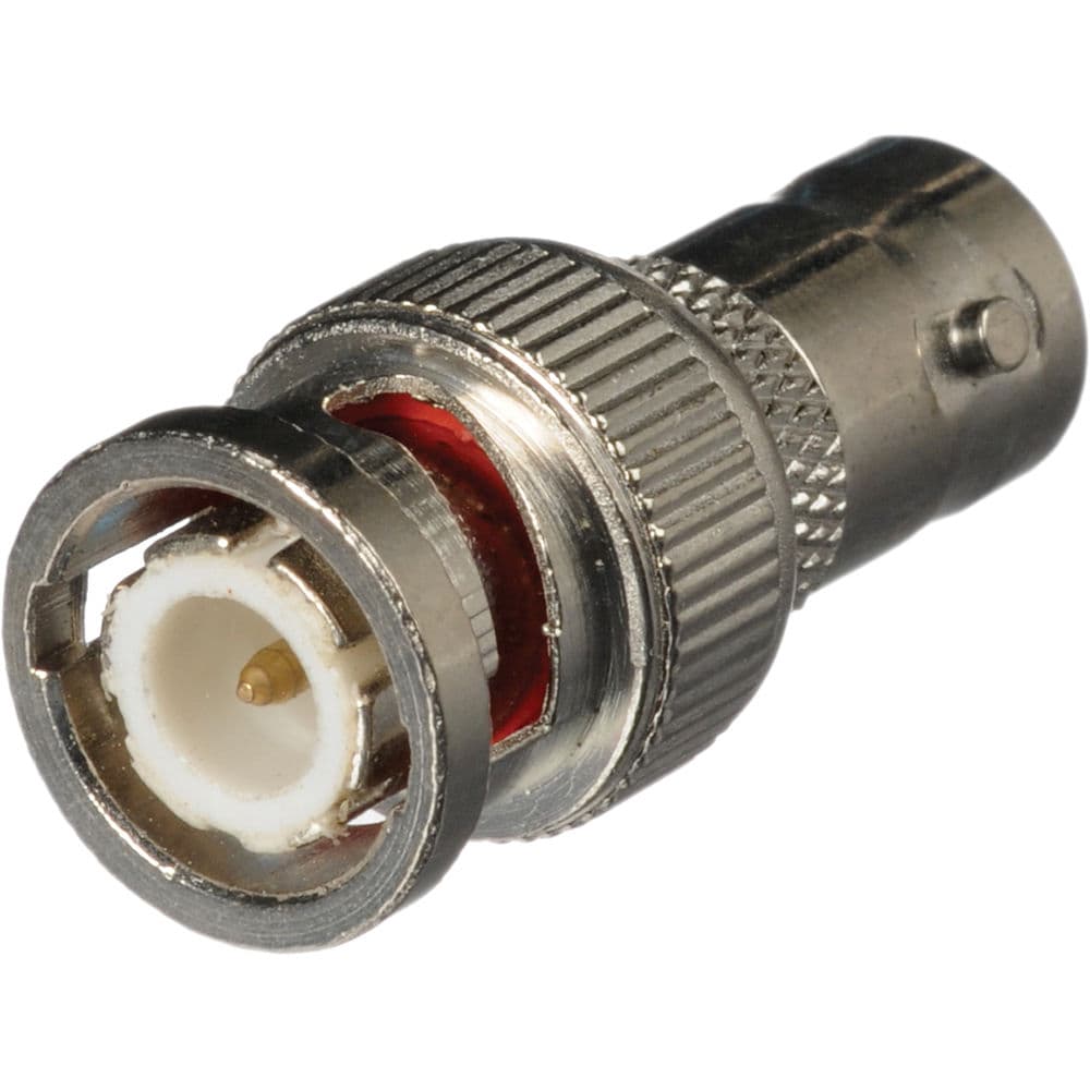
Figure 6: MBNC Connector
Twin BNC Connectors (Twinax)
These connectors combine two BNCs into one unit and useful when two separate signal channels are required. They’re often used in systems where the signals need to be kept separate or isolated.
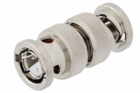
Figure 7: Twin BNC Connector
Triaxial BNC Connectors
These connectors provide extra shielding to protect against interference from other electronic signals. They are used in scientific tests or environments with high electromagnetic interference, ensuring a clear signal.
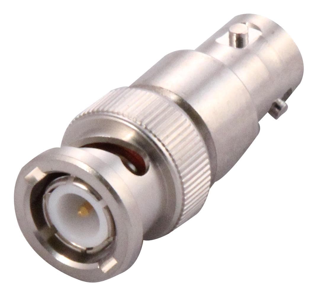
Figure 8: Triaxial BNC Connector
BNC Formats
Plugs and Sockets: The most basic and common format of BNC connectors consists of plugs and sockets. The plug, often referred to as the male connector, is inserted into the socket or female connector. These connectors are engineered for easy, quick connection and disconnection using the bayonet locking mechanism that provides a reliable connection without the need for tools. Plugs are frequently used on cables, while sockets are found on devices and panels.
Adapters: BNC adapters allow for flexibility in system design by enabling the connection between different types of cables or devices. Adapters come in various forms, including male-to-male, female-to-female and mixed gender configurations. They can convert between different connector types, such as from BNC to SMA (SubMiniature version A) or other RF connectors.
Attenuators: In certain applications, signal strength needs to be controlled, especially in sensitive RF systems where high power levels can distort performance. BNC attenuators help by reducing the signal strength to the desired level, providing improved control over signal flow and preventing equipment damage or interference.
BNC Design Variations
Straight BNC Connectors: Straight connectors are the most straightforward design, preferred for their simplicity and ease of installation. They allow the cable to extend directly outward from the connection point, making them ideal for setups where space constraints are not an issue. Their direct path ensures minimal signal loss and preserving the integrity of the RF transmission.
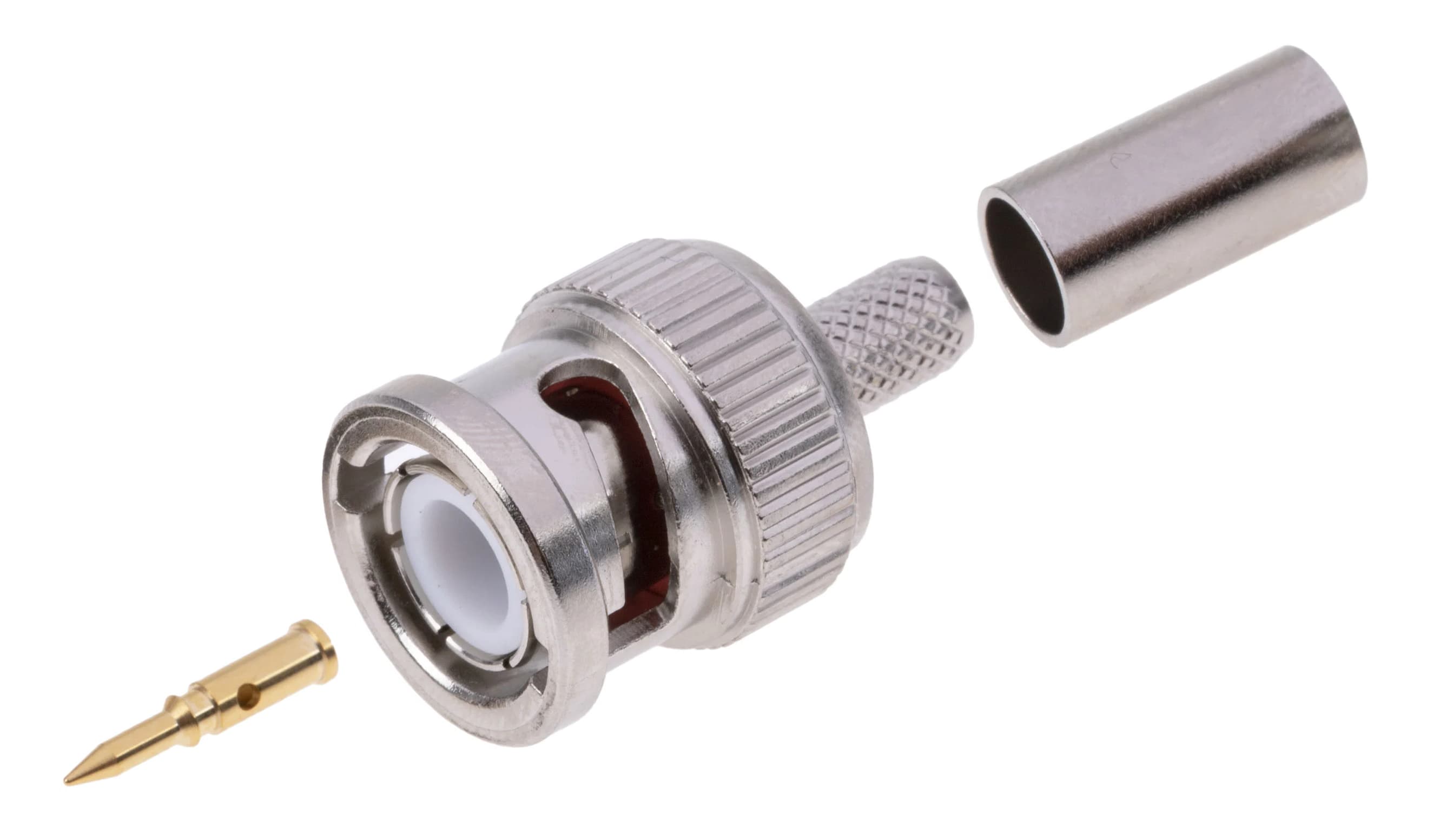
Figure 9: Straight BNC Connector
Right-Angle BNC Connectors: Right-angle BNC connectors are designed for applications where space is limited such as in densely packed electronic racks or behind equipment that is placed against walls. While these connectors are useful in tight spaces, they may introduce a slight amount of signal degradation due to the change in signal path direction. However, this signal loss is minimal and can be compensated for in the system design.
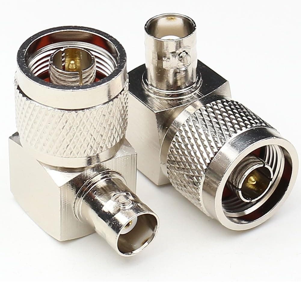
Figure 10: Right-Angle BNC Connector
Panel-Mount Connectors: Some systems require connectors that can be mounted on panels or enclosures. These panel-mount BNC connectors are designed with flanges or nuts to secure them in place, providing a stable and secure connection point on equipment. Depending on the design, they may offer enhanced grounding or shielding capabilities to improve signal integrity.
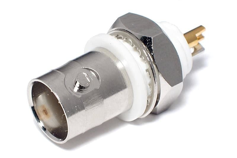
Figure 11: Panel-Mount Connector
Different Types of Female BNC Connectors
Female BNC connectors, also called sockets, come in different types to meet various needs for grounding and shielding. These differences are important to keep the signal strong and make sure the system works well in radio frequency (RF) setups.
Single-Nut Connectors: This style is used for lower-frequency systems where grounding and matching the signal’s impedance (resistance) are not as required. It’s easy to install, making it a good choice for simple uses that don’t need high accuracy.
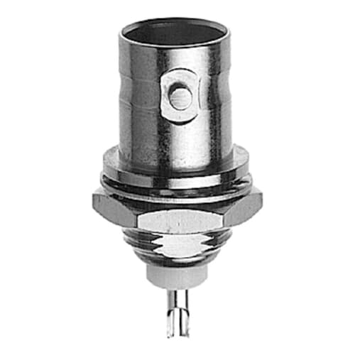
Figure 12: Single-Nut Connector
High-Frequency Connectors: For more complex uses in systems working at higher frequencies, female BNC connectors are made with more care to match impedance and keep signal quality high. These high-frequency designs may include extra grounding parts or use special materials to cut down on interference and keep the signal clear. In these cases, even small mismatches in impedance can cause the signal to reflect or weaken, so these connectors are built to ensure the best performance possible.
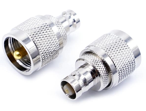
Figure 13: High-Frequency Connector
How to Assemble BNC Connectors?
• Choose the Right Connector and Cable
Start by picking the correct BNC connector and coaxial cable. Make sure the impedance of the connector (usually 50 or 75 ohms) matches the cable. Also, decide on the assembly method: crimp, compression, or solder. Each method needs different tools, so pick the one that works best for you.
• Prepare the Cable
Careful cable prep is required for a good connection. Use a coaxial cable stripper to remove the outer cover, the insulating layer, and the shielding. This will reveal the inner wire, making it ready for the connector. Follow the length guidelines from the connector’s instructions and fold back the shield mesh.
• Attach the Connector
Crimp Method: Slide a crimp ferrule onto the cable then insert the cable into the connector. The inner wire should stick out through the connector tip. Slide the ferrule up and use a crimping tool to secure it over the cable's outer layers.
Compression Method: Push the cable into the connector until the insulation is even with the connector's inner post. Use a compression tool to tighten the connector onto the cable.
Solder Method: After preparing the cable, insert it into the connector. Solder the center pin to the inner wire. In some cases, you may need to solder the connector body to the cable's shield too.
• Test the Connection
Once the connector is attached, test the connection to make sure it’s working. Use a cable tester or multimeter to check for shorts or bad connections, ensuring everything meets the system's needs.
• Final Touches
For extra protection, use heat shrink tubing over the area where the connector meets the cable. This will protect the connection and give it a more polished look.
Compression Gland vs. Crimp Methods
Compression Gland Method
The compression gland method for putting together BNC connectors is very flexible and works well for smaller or custom projects. It’s often chosen when precision, flexibility, and easy assembly are required.
This method uses a soldered pin to connect the center of the coaxial cable. After that, a gland holds the cable’s shield (the braid) and outer covering in place. The compression from the gland creates a tight fit, providing good shielding and proper grounding to keep the signal strong for high-frequency use.
Advantages Disadvantages
The compression gland method fits various cable sizes, making it versatile for projects using different types of cables. May not be as fast or consistent as other methods like in larger production jobs.
Unlike the crimp method, this approach doesn't require specialized tools. Basic tools like a soldering iron and wrenches are sufficient. For quick, high-volume connector production, the crimp method might be a better choice.
Suitable for labs, custom builds, or small projects where specialized tools aren't required and production volume is low. The compression gland method may lack the consistency provided by more standardized methods like crimping that could impact quality in repetitive tasks.
Crimp Method
The crimp method is the best choice for big projects where you need fast, reliable, and uniform connections. It uses special tools to tightly secure both the center pin and the cable for a strong and consistent connection.
How it works? First, you strip the coaxial cable to reveal the center conductor and shield. Then, a pin is crimped onto the center conductor, and a metal sleeve is crimped over the braid and outer covering. Crimping tools apply the right pressure to ensure a secure, long-lasting connection that can handle tough conditions like vibration and stress.
|
Advantages |
Disadvantages |
|
The crimp method saves time, making it perfect for mass production or large installations like in telecom, broadcasting, or big networking setups. |
Requires specific tools and careful cable preparation. Without the right tools or proper preparation, it can result in poor connections that harm signal quality or cause failures. |
|
Crimped connections are durable and reliable, reducing the chance of signal loss or loose connections. |
Incorrect crimping can lead to bad connections, that could result in signal degradation or operational failures. |
|
Crimping tools are fast and produce consistent results, making them ideal for high-volume work where quality and uniformity matter. |
Potentially higher initial cost due to the need for specialized tools. |
Comparing BNC, SMA and RCA Connectors
|
Connector Type |
Best For |
Connection Type |
Advantages |
Common Uses |
|
BNC |
Professional, high-reliability jobs |
Twist-and-lock |
Strong, stable, and secure connection |
TV studios, medical equipment, broadcasting |
|
RCA |
Everyday consumer electronics |
Push-in |
Easy to use, affordable |
Home audio/video systems, consumer electronics |
|
SMA |
High-frequency, advanced systems |
Screw-on |
Handles very high frequencies, small size |
Satellite systems, microwave communications |
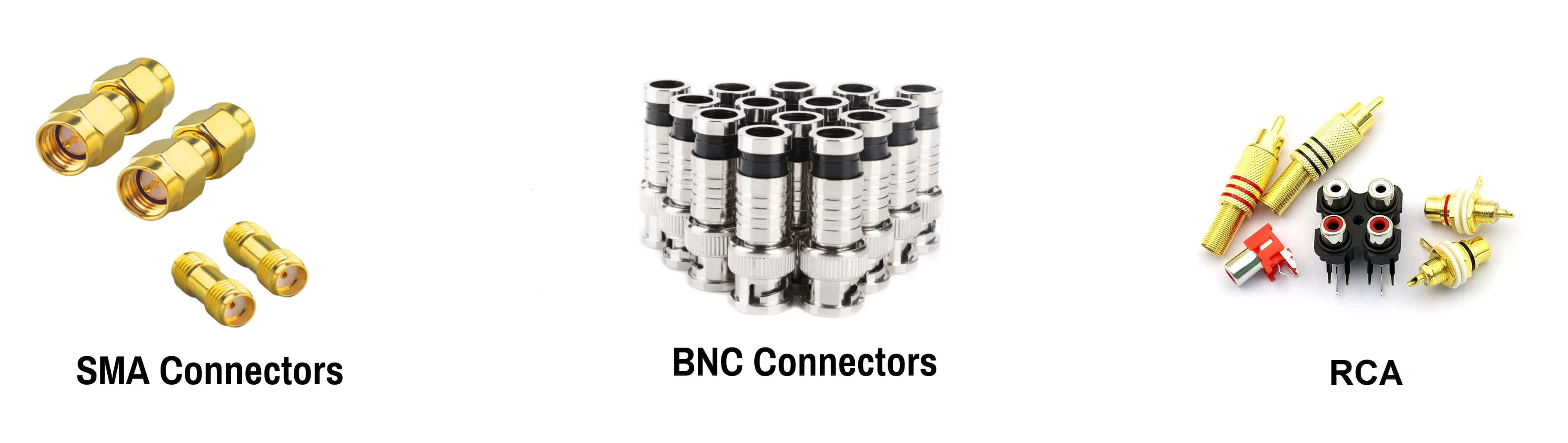
Figure 14: BNC, SMA and RCA Connectors
Cable Compatibility with BNC Connectors
BNC connectors are versatile and work with many types of coaxial cables. Some common cables used with BNC connectors include RG-59, RG-6, and RG-11.
RG-59 is great for shorter distances and frequently used in analog video applications, such as CCTV systems. Its relatively thin design makes it easy to install in tight spaces, though it's best suited for lower-frequency signals and applications that don't require long cable runs.
RG-6 is stronger and having higher signal quality than RG-59. It is used in digital video transmission and internet connections. Its thicker insulation and ability to handle higher frequencies make it a go-to choice for setups that demand more robust performance.
RG-11 is known for its ability to maintain signal integrity over long distances. RG-11 is the preferred option for high-definition TV broadcasts, satellite installations, and telecommunication systems. Its thicker diameter reduces signal loss, making it ideal for situations where long cable runs are required without sacrificing quality. Because BNC connectors can work with different cables, they are used in both home and professional settings. This flexibility makes them useful in many situations, from home electronics to specialized tech setups.
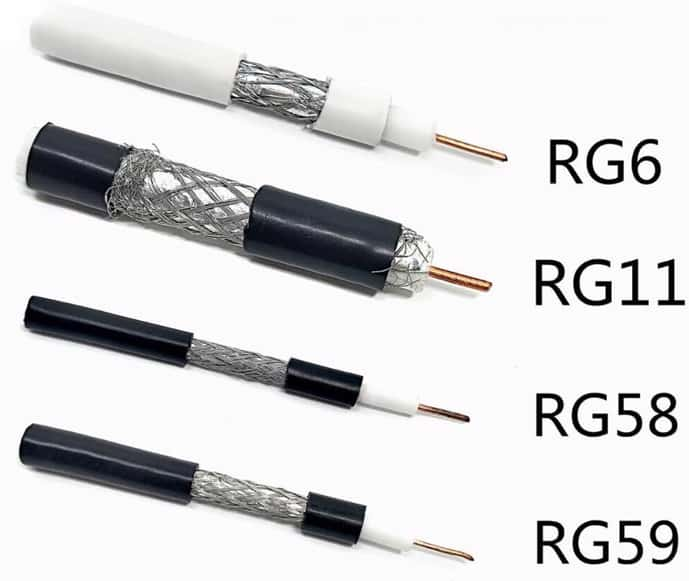
Figure 15: Cable Compatibility with BNC Connectors
Conclusion
This article highlights the important role that BNC connectors play in modern electronics and telecommunication systems. It covers everything from the basic types and designs to more complex assembly techniques, showing how flexible and important these connectors are for creating strong, interference-free connections in various situations. The comparison with other connectors shows why BNC connectors are often chosen for reliable uses like broadcasting and medical equipment. The discussion of cable compatibility also shows how practical and adaptable BNC connectors are for different cable types, helping them work well in many settings. Overall, this article gives a better understanding and serves as a useful guide for choosing the right BNC connector to improve system performance and reliability in the fast-changing world of RF technology.
Frequently Asked Questions [FAQ]
1. Can BNC connectors be reused?
BNC connectors can be reused if they remain in good physical condition and maintain electrical integrity. The main factors determining reusability are the absence of physical damage to the connector body and pins, and the ability to maintain a secure and stable connection when mated. Before reusing a BNC connector, inspect it for bent pins, worn or damaged threads, and any other signs of wear or damage that could compromise the connection.
2. What is a BNC adapter?
A BNC adapter is a device used to interface between BNC connectors and other types of connectors or between different genders or impedances of BNC connectors. It serves as a bridge, enabling compatibility and extending the functionality of existing cable setups. Common types include BNC to SMA, BNC to N-Type, or gender-changing adapters from male to female BNC connectors.
3. What is a BNC splitter?
A BNC splitter is used to divide a single BNC input into multiple outputs, allowing a signal to be distributed to several devices. It is used in video applications, where a single camera feed needs to be sent to multiple monitors or recording equipment. The splitter must be capable of handling the bandwidth and frequency of the signal to avoid degradation.
4. What is a BNC male and female connector?
A BNC male connector is characterized by a metal pin at the center and a rotating ring with bayonet lugs used to secure it to a female connector. The female BNC connector, in contrast, features a receptacle for the male pin and slots to accommodate the bayonet lugs of the male connector. This design allows for quick connect and disconnect while ensuring a stable and reliable coaxial connection.
5. What is the maximum frequency that can be transmitted using BNC connectors?
The maximum frequency that can be effectively transmitted using BNC connectors is typically up to 4 GHz. However, the actual usable frequency range can depend on the specific design and quality of the connector. High-quality BNC connectors can handle frequencies at the upper end of this range but standard types are more used up to 2 GHz. For applications requiring higher frequencies, connectors like SMA or N-Type are recommended due to their better performance at high frequencies.