Balun
In radio frequency (RF) communication, keeping signals clear and strong is a top priority. One device that plays a big role in this process is the balun. A balun, which stands for "balanced to unbalanced," helps connect two different types of systems—balanced and unbalanced—without letting the signal get weak or noisy. By reducing interference, baluns make sure the signal stays clean and effective as it moves through different parts of the system. In this article, we’ll take a close look at baluns, explaining what they do, the different types available, and how they are used in real-life situations. This will give you a better understanding of why they are so helpful in RF antenna systems.Catalog
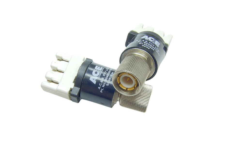
Figure 1: Balun
What Is a Balun?
A balun, short for "balanced to unbalanced," is a device that allows signals to move between two types of systems: balanced and unbalanced. In a balanced system, the signal travels through two wires with equal but opposite voltages, reducing noise. In an unbalanced system, a single wire carries the signal, with the ground as a reference, making it more prone to noise.
The balun’s job is to convert signals between these systems without losing signal strength or adding noise. It uses a special design with wire coils around a magnetic core to match the electrical properties between the two systems, ensuring smooth signal transfer.
Baluns are commonly used in radio frequency (RF) communication, especially with antennas. For instance, a balanced dipole antenna often connects to an unbalanced coaxial cable through a balun to prevent signal problems. Without a balun, the signal could weaken or pick up noise, reducing quality.
Baluns also help in other areas like broadcast antennas and video transmission, keeping signals clear and strong during conversion. In summary, a balun ensures that signals move smoothly and remain clear when transitioning between balanced and unbalanced systems.
Why Are Baluns Needed?
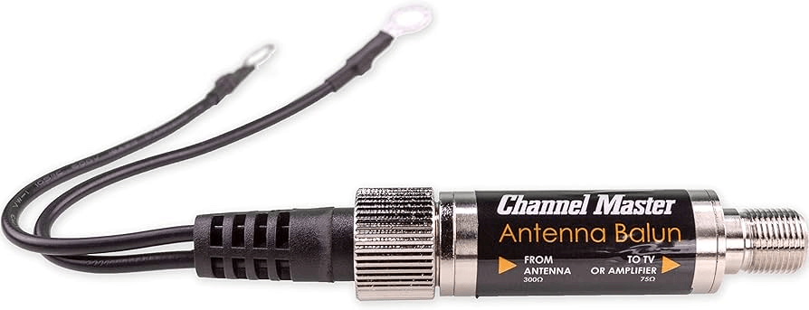
Figure 2: Antenna Balun
Baluns are important parts of antenna systems, doing jobs that help the system work better and more efficiently.
Stopping Unwanted Radiation or Signal Pickup: When you connect a balanced antenna directly to an unbalanced coaxial cable, the outer part of the coaxial cable might accidentally send out or pick up signals. This can lead to interference during signal reception or cause unwanted radiation when transmitting. Baluns fix this by making sure the coaxial cable works correctly, reducing these problems significantly.
Keeping the Antenna's Radiation Pattern: Without a balun, the unintended radiation or signal pickup by the coaxial cable can mess up the antenna’s designed radiation pattern, leading to poorer performance. By using a balun, the antenna’s radiation pattern stays the same, protecting the performance and direction of the signal.
Reducing RF Radiation Near the Transmitter: Sometimes, RF signals can come from the feeder instead of the antenna, causing interference around the transmitter. This can be especially troublesome in data transmission systems, where RF interference can mess up connections between the transmitter and other devices. A balun helps with this by making sure the RF signals are sent out the right way, reducing the chance of interference.
Types of Baluns in RF Antenna Systems
Baluns are devices used in RF (Radio Frequency) antenna systems to change signals between balanced and unbalanced lines. There are different types of baluns, each made to meet specific needs in these systems. Here’s a detailed look at the different types:
Transformer Balun
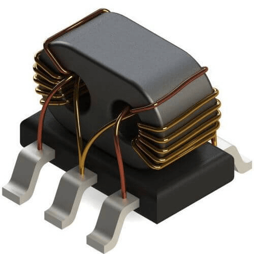
Figure 3: Transformer Balun
A Transformer Balun is a common and widely used type in RF systems. It has two separate windings, or coils, wrapped around a ferrite core. These windings keep the balanced and unbalanced sides of the system separate from each other, which helps to prevent interference and keeps the signal clear. The way the transformer balun adjusts impedance (which is a kind of electrical resistance) depends on the number of turns in the two windings. For instance, if one winding has twice as many turns as the other, it can match an impedance of 100 ohms on the balanced side to 50 ohms on the unbalanced side. This feature makes it useful for matching different impedance levels.
Autotransformer Balun
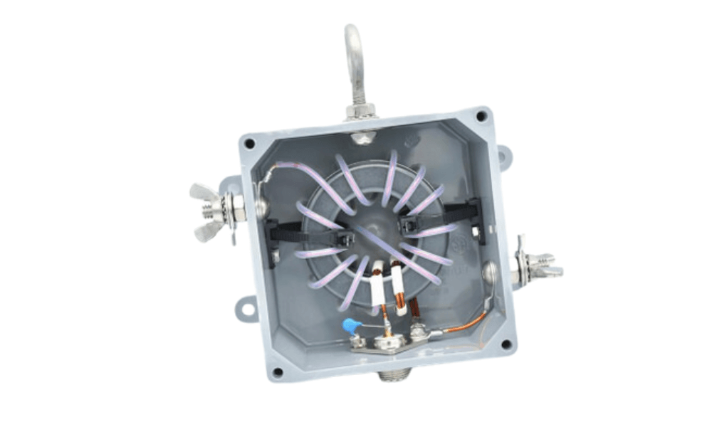
Figure 4: Autotransformer Balun
The Autotransformer Balun is different from the transformer balun because it uses just one winding to change the signal. This single-winding design allows a direct current (DC) path to the ground for all connections, which helps to safely release static electricity that can build up on external antennas. The autotransformer balun is often used in systems where having a ground connection is very important for both safety and proper function. Because it only has one winding, this balun is usually simpler and smaller than transformer baluns, though it might not provide the same level of separation between the balanced and unbalanced sides.
RF Choke Balun
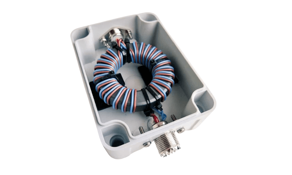
Figure 5: RF Choke Balun
An RF Choke Balun works by increasing the inductance (which resists changes in current) on the outer conductor of a coaxial cable. This increased inductance helps block unwanted RF signals from traveling along the conductor, which can cause interference and reduce the performance of the antenna system. A common way to make an RF choke balun is by coiling the coaxial cable at the point where it connects to the antenna, creating a "feed-line choke." This method is simple and effective in improving performance. Another method is to wrap the coaxial cable around a toroidal ferrite core, which further increases inductance and provides a strong choke.
Current vs. Voltage Baluns
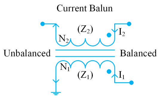
Figure 6: Current Balun
A current balun operates by ensuring that equal current flows through both sides of a balanced load. This balance prevents common-mode currents that can cause signal distortion and interference. The current balun achieves this by using a design that forces the current in each conductor to be equal and opposite, such as with bifilar windings or coaxial cables wound around a ferrite core. This configuration not only minimizes the potential for radiation from the feed line but also helps maintain the integrity of the transmitted signal.
The current balun's design makes it highly effective in applications where the primary goal is to ensure that the balanced load receives equal and opposite currents, which is necessary for reducing interference and signal degradation. This characteristic makes the current balun particularly suited for antenna systems.
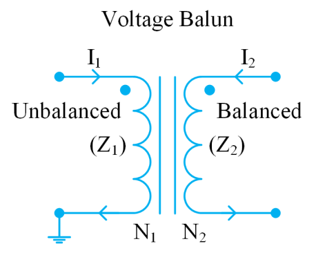
Figure 7: Voltage Balun
On the other hand, a voltage balun is designed to ensure that both sides of a balanced load experience equal voltage. The voltage balun does this by imposing equal voltages on both sides of the load, but it doesn’t necessarily ensure that the currents are equal. This can be problematic because unequal currents can lead to common-mode currents, which are less desirable in RF applications due to the potential for interference and signal loss. Voltage baluns are often less effective at preventing these issues compared to current baluns, which is why they are less commonly used in high-performance antenna systems. However, they may still find application in situations where voltage balance is more critical than current balance, though these scenarios are less frequent in RF applications.
How Dose a Balun Work?
The Basic Concept of a Balun
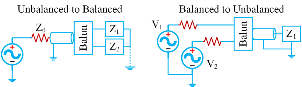
Figure 8: Unbalanced to Balanced Feeder and Balanced to Unbalanced Feeder
A balanced antenna or feeder has two wires carrying equal currents but in opposite directions, while an unbalanced coaxial cable has one wire with a grounded shield. To connect these two systems without causing problems, a balun keeps them separate.
This separation is done through a transformer, a main part inside the balun. The transformer has two sets of coils, one connected to the balanced system and the other to the unbalanced system. The coils are designed to prevent the grounding of the unbalanced system from affecting the balanced system. In simple terms, the balun makes sure the balanced system works independently and isn't disturbed by the unbalanced cable.
Impedance Matching and Bandwidth

Figure 9: Impedance Matching
This diagram shows how impedance matching works in a radio communication system, helping ensure the signal moves smoothly between different parts like the antenna, Band Pass Filter (BPF), and transceiver. BALUNs, which are transformers, play a major role in adjusting the impedance between these parts. For instance, the antenna has a 400 Ohm impedance, and the BALUN changes it to 50 Ohms to match the transmission line and BPF. The BPF filters the signal, allowing only the desired frequencies to pass through. After filtering, another BALUN adjusts the impedance to match the 200 Ohm resistance of the transceiver.
Baluns do more than just connect different systems; they also help match the resistance of the antenna or feeder to the standard 50 Ohms of the coaxial cable. Matching is important because if the impedance isn't aligned properly, the signal can bounce back, causing reduced efficiency and potential signal loss. Baluns are designed to adjust the resistance for better signal transfer with minimal loss. However, they work well only within a certain range of frequencies, known as bandwidth. For the balun to work properly, its bandwidth must cover the full range of frequencies that the antenna or system uses. A wider bandwidth allows the balun to handle various frequencies without losing performance, helping the system run efficiently.
Practical Applications and Considerations of Baluns in Antenna Systems
Antenna Systems and Balun Use
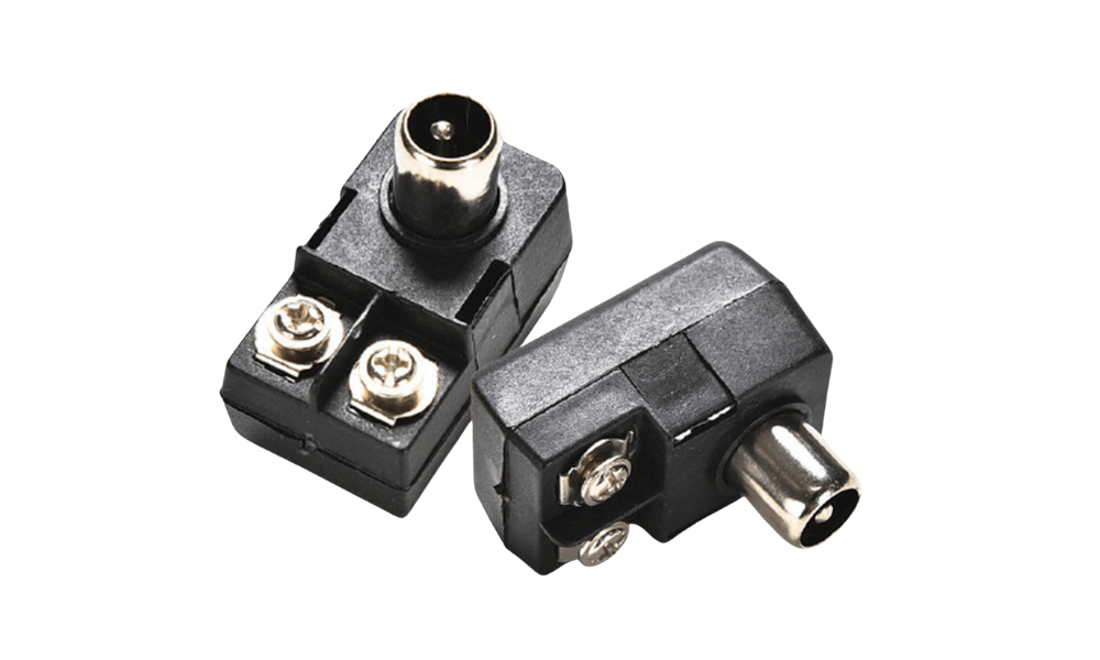
Figure 10: Balun For Antenna Systems
Baluns are commonly used in antenna systems, especially with dipole antennas. In these setups, the balun is placed at the point where the antenna connects to the coaxial cable. The main job of the balun here is to link the balanced parts of the dipole antenna to the unbalanced coaxial cable. This connection is needed because dipole antennas naturally have equal and opposite currents on each side, while coaxial cables carry current only on the inner wire. The balun makes sure these two different systems work well together, helping th signal to pass through without problems.
Without a balun, connecting the antenna directly to the cable can cause issues like signal reflection, interference, and reduced efficiency. The balun helps prevent these problems by keeping the electrical match between the antenna and the cable, which reduces signal loss and allows the antenna system to work properly.
Mounting and Weather Protection for Outdoor Baluns
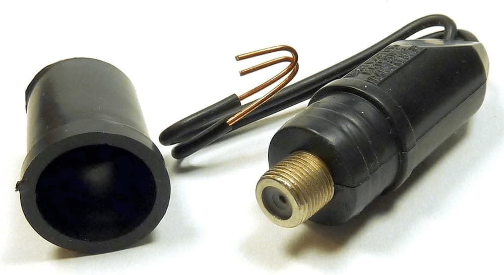
Figure 11: Weatherproof Balun for Outdoor Antenna Systems
When using baluns in outdoor antenna systems, they need to be built to handle tough weather conditions. Sun, rain, heat, and cold can affect how well a balun works if it’s not properly protected. To keep the balun working well, it should be sealed correctly to stop water from getting inside. Water inside a balun can cause short circuits or change how it works, leading to signal loss or even making the antenna system stop working.
Also, the way the balun is attached should include features that relieve strain. Strain relief is important because it prevents physical stress on the balu’s connections, which could otherwise wear out over time and lead to failure. For example, in strong winds, the antenna system might move, putting stress on the balun. A well-designed strain relief will protect the connections, making sure the balun stays securely attached and keeps working properly even in these conditions.
Conclusion
Baluns are useful parts of RF antenna systems that help signals move smoothly between balanced and unbalanced systems while keeping them clear of noise and interference. Whether it’s a transformer balun, autotransformer balun, or RF choke balun, each type has a specific job that helps the antenna system work better. Knowing how baluns work and using the right one can make your RF communication system more efficient and reliable. As we’ve discussed, baluns help match different parts of the system, stop unwanted signals, and keep the antenna working properly. By choosing the right balun, you can make sure your RF signals stay strong and clear, leading to better overall performance.
Frequently Asked Questions [FAQ]
1. Where should a balun be placed?
A balun should be placed where a balanced antenna, like a dipole, connects to an unbalanced transmission line, such as a coaxial cable. This spot is the best place to make sure the signal moves smoothly and doesn’t pick up noise or interference.
2. Do I need a balun for a dipole?
Yes, you need a balun for a dipole antenna when it's connected to an unbalanced transmission line, like a coaxial cable. The balun helps keep the signal from getting distorted or picking up interference, allowing the dipole to work properly.
3. What is the most common type of balun?
The most common type of balun is the transformer balun. It's widely used in RF systems to help match the connection between balanced and unbalanced parts, making sure the signal stays clear.
4. Is a balun just a transformer?
A balun isn’t just a transformer, though many baluns work like transformers. A balun can also use other designs, like an autotransformer or an RF choke, to balance and unbalance signals.
5. What are the different types of baluns?
The different types of baluns include transformer baluns, autotransformer baluns, and RF choke baluns. Each type is made for specific uses and has different ways of balancing or unbalancing the signal.