Application of Ohm's Law in Series Circuits
Electrical circuits, whether simple or complex, are governed by fundamental laws that predict their behavior under various conditions. A series circuit, characterized by a single continuous path through which the current flows, provides a clear example of these principles in action. For efficiently and safely developing, evaluating, and debugging electrical systems, it is required to comprehend how current behaves in such a circuit The article digs into the complexities of series circuits, emphasizing the uniformity of current flow, the application of Ohm's Law, and the distribution of resistance. Through practical examples and detailed calculations, it examines the operational dynamics of series circuits, exploring both single and multiple resistor configurations, and extends these concepts to the analysis of parallel circuits. The exploration begins with an understanding of the nature of current in a series circuit, likened to marbles moving uniformly through a tube, and broadens to include comprehensive applications of Ohm's Law in determining circuit behavior. This foundational understanding paves the way for further discussions on more complex configurations and their implications in real-world electrical applications.Catalog
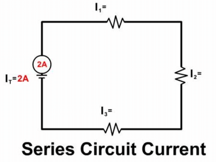
Figure 1: Series Circuit
Current Dynamics in Series Circuits
In a series circuit, the electrical current flows through a single, continuous path, ensuring the same current passes through each component. Similarly, water flowing through an unbranched hose maintains a uniform rate. This illustrates why every component in a series circuit experiences the same current.
To effectively analyze and predict how a series circuit behaves under different conditions, it’s dominant to use Ohm's Law. This law explains the connection between voltage, current, resistance, and power in a circuit. When applying Ohm’s Law, you must measure voltage, current, and resistance between the same two points. This ensures that your calculations of voltage drops and current flows are accurate and reflect the actual conditions in the circuit.
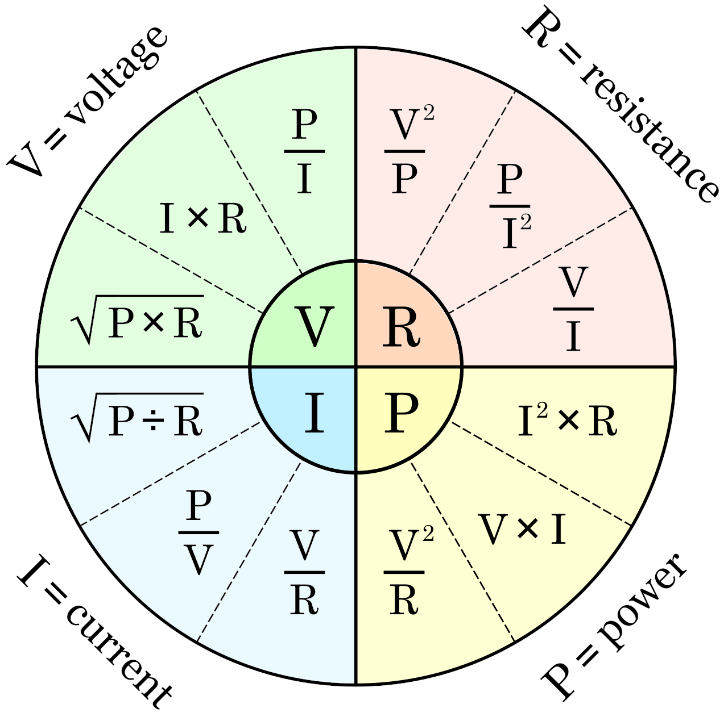
Figure 2: Ohm’s Law in Circuit
Implementing Ohm's Law in Circuits with a Single Resistor
When examining a basic series circuit that includes a single resistor and a battery, it is needed to understand how the components are connected. Points in the circuit that are linked by conductors with minimal resistance are considered electrically identical. For example, in a circuit with a 9V battery and a resistor, points 1 and 4 mark the terminals of the battery and the resistor, respectively. The voltage across the resistor, between points 2 and 3, is 9V. This setup demonstrates Kirchhoff's Voltage Law, which states that the sum of all voltages around any closed-circuit loop must equal zero.
Using Ohm's Law, represented by the equation we can easily calculate the current flow through the resistor. Here,I is current, V is the voltage, and R is the resistance. To apply this in our example, we consider the voltage across the resistor (points 2 and 3) and the resistance value.
Example Calculation
Assume the resistor value is 3 kΩ. The current flowing through the resistor is calculated as follows:
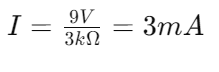
This calculation provides a direct measure of current based on known voltage and resistance values. It allows engineers to precisely identify and address issues related to voltage drops and current distributions within the circuit. Applying Ohm’s Law in this manner enhances the reliability and efficiency of electrical system diagnostics and maintenance, ensuring accurate and effective problem-solving.
Ohm's Law in Action: Series Circuits with Multiple Resistors
When dealing with series circuits that include multiple resistors, applying Ohm's Law requires a more detailed approach due to the way voltage is distributed across each resistor. The total voltage from the battery (e.g., 9V between points 1 and 4) remains constant, but the voltage drop across each resistor varies based on their resistances. This is because the total voltage is divided among the resistors in proportion to their resistance values.
Calculating Total Resistance
First, calculate the total resistance of the circuit by summing the resistance values of all resistors in series. For example, if you have three resistors R1, R2, and R3, the total resistance Rtotal is given by:Rtotal = R1+R2+R3
Determining the Total Current
Once the total resistance is known, use Ohm’s Law to find the overall current flowing through the circuit:

Example Calculation
Suppose R1 is 2kΩ, R2 is 3kΩ, and R3 is 5kΩ. The total resistance Rtotal would be:

Using a 9V battery, the total current III is:
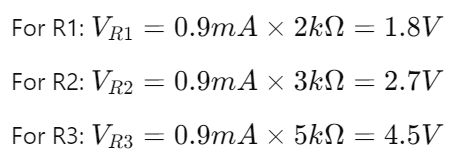
In a series circuit, the same current flows through all components. To find the voltage drop across each resistor, apply Ohm’s Law V = IR.
These calculations provide a clear understanding of how voltage is distributed and current flows in the circuit. This knowledge is needed for troubleshooting and optimizing circuit performance. By methodically analyzing voltage drops and current flow, you can enhance the practical application of Ohm's Law in more complex series circuit scenarios, ensuring precise and effective circuit design and maintenance.
Simplifying Multiple Resistors into a Single Equivalent
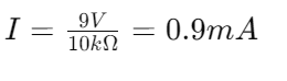
In series circuits, calculating the total resistance is straightforward. It involves summing the resistances of all resistors connected end-to-end. This technique simplifies the complexity of electrical circuits, allowing them to be represented as a single equivalent resistor. This simplified model makes it easier to analyze and understand the circuit's behavior.Consider a series circuit with three resistors: 3 kΩ, 10 kΩ, and 5 kΩ. To find the total resistance you simply add these values:
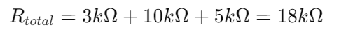
This 18 kΩ total resistance models the combined opposition to the current flow presented by the three resistors.
The equivalence of this setup to a circuit with a single 18 kΩ resistor simplifies both theoretical calculations and practical applications. For instance, when designing a circuit or performing diagnostics, engineers and technicians can quickly estimate voltage drops, current flow, and power dissipation using this simplified model. This approach enhances the efficiency of circuit analysis and troubleshooting.
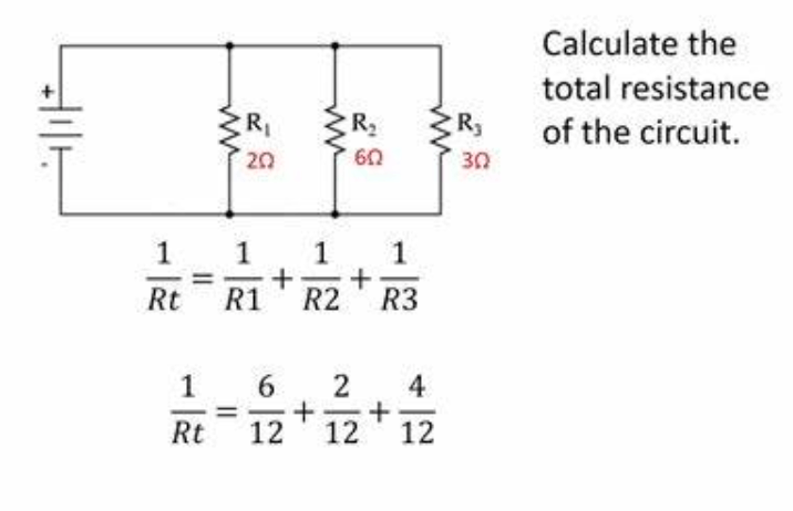
Figure 3: Total Resistance in Series Circuits
Figuring Total Resistance in Series Circuits
Calculating the total resistance in a series circuit is required to understand the circuit's overall electrical properties, such as current flow and power distribution. In a series circuit, each resistor adds to the total resistance, affecting how easily the current can flow. This accumulation of resistance increases the circuit's total impedance, reducing the current according to Ohm's Law.
To determine the total resistance in a series circuit, you simply add the resistance values of all the resistors. For example, in a circuit with resistors valued at 2 kΩ, 4 kΩ, and 6 kΩ, the total resistance is calculated as follows:
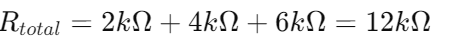
This total resistance Rtotal of 12 kΩ acts as the single limiting factor for the current throughout the circuit.
With the total resistance Rtotal known, you can calculate the current flowing through the circuit when a specific voltage is applied. For instance, with a 12V power supply, the current I is:
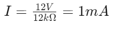
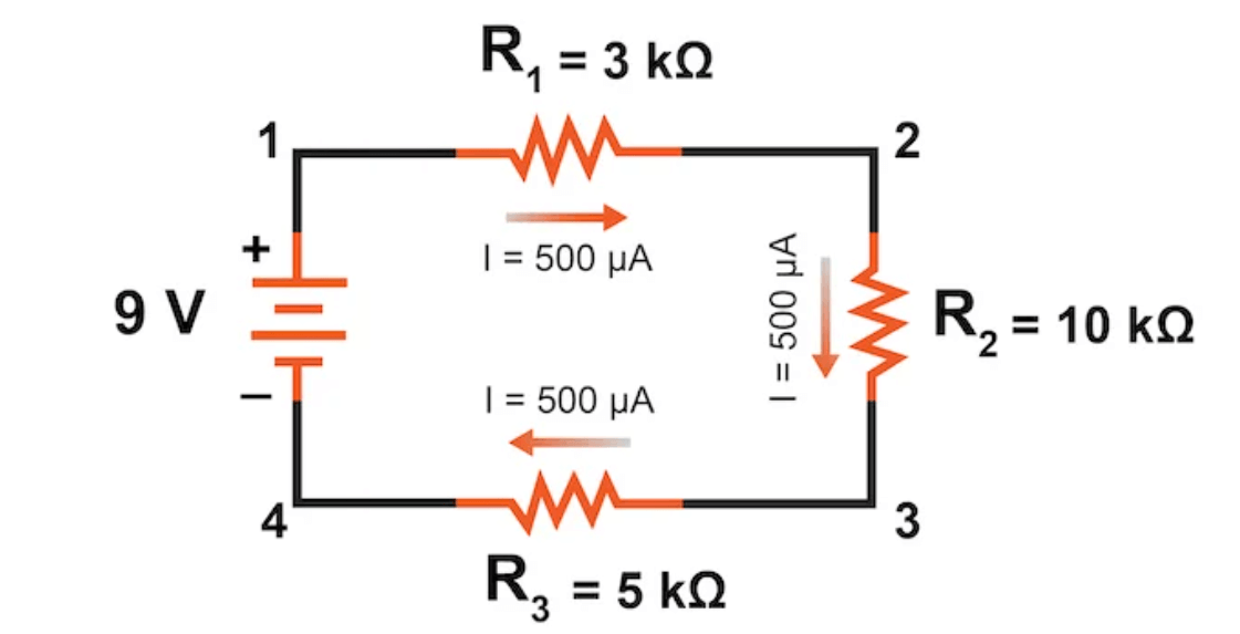
Figure 4: Calculating Circuit Current in Series Circuits
Calculating Circuit Current in Series Circuits
Once you have determined the total resistance in a series circuit, you can use Ohm’s Law to calculate the circuit’s total current. This process is key for understanding and managing the circuit's performance. Consider a series circuit with a total resistance of 18 kΩ and a supply voltage of 9V. Using Ohm’s Law, which is expressed  , you can calculate the current flowing through the circuit. Given these values, the calculation is:
This result, 500 μA, represents the total current flowing through every component in the series circuit.
It must be maintained to comprehend the circuit's current to assess both its performance and safety. This allows engineers and technicians to predict its behavior under operational conditions and design it to avoid overloading and potential failure. Accurate current calculation is primary for troubleshooting, as it helps identify problems like excessive resistance or unexpected voltage drops across components, indicating faulty or degraded parts. This analytical approach ensures the circuit's efficiency and reliability. These also enhance maintenance procedures with clear metrics for monitoring circuit health.
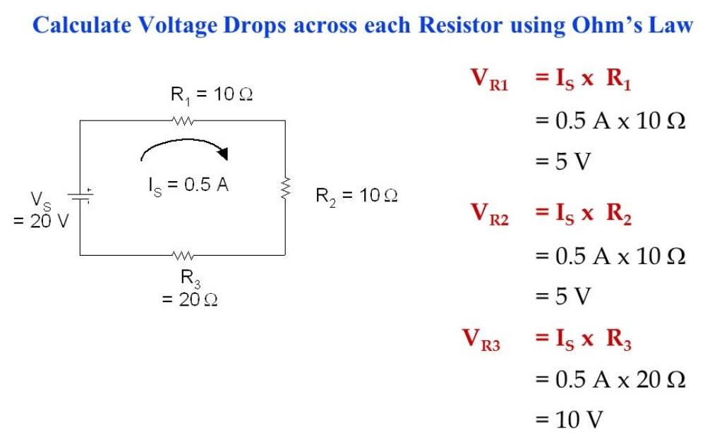
Figure 5: Voltage Drop
Voltage Drop Analysis in Series Circuits
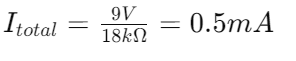
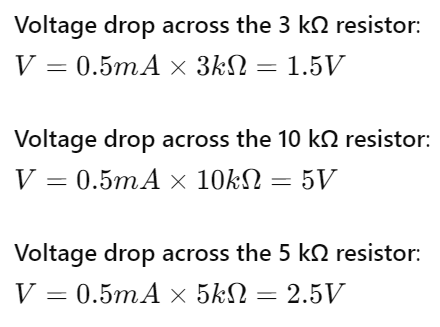
Calculating the voltage drop across each resistor in a series circuit is straightforward once you know the total current flowing through the circuit. The voltage drop across any resistor is proportional to its resistance and the total current, following Ohm’s Law(V =IR)
Suppose the total current in the circuit is 500 μA (0.5 mA), and the resistors in series are 3 kΩ, 10 kΩ,
Verification with Kirchhoff's Voltage Law
The sum of these voltage drops is:
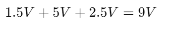
This matches the total voltage supplied by the battery, confirming Kirchhoff's Voltage Law, which states that the total voltage around any closed loop in a circuit must equal zero, accounting for voltage rises and drops.
Series Circuit Principles
In a series circuit, the ultimate principle is that the same current flows through each component without any variation. This uniformity is central for predicting how different elements within the circuit will behave under various electrical loads. Knowing that the current remains constant simplifies the analysis and design of series circuits.
Another main characteristic of series circuits is the additive nature of resistances. The total resistance in a series circuit is the sum of the individual resistances. This cumulative resistance directly affects the total current flow, as described by Ohm’s Law (V=IR) The higher the total resistance, the lower the current for a given voltage. This connection is unsafe for understanding the circuit’s overall performance and efficiency.
Calculating Voltage Drops
Calculating voltage drops across each component is a must. The voltage drop across any resistor in a series circuit can be found by multiplying the current by the resistor's resistance The sum of these individual voltage drops must equal the total voltage supplied by the battery. This confirms Kirchhoff’s Voltage Law, which states that the sum of all voltages around any closed loop must be zero, ensuring energy conservation within the circuit. It enhances their practical utility in various applications, from simple electronic devices to complex electrical systems.
Key Principles of Series Circuit Dynamics
Law of Total Resistance
The total resistance in a series circuit is the sum of all individual resistances along the path. This law is foundational for calculating the circuit's overall resistance, which directly affects how much current flows through the circuit. For example, if a circuit includes resistors of 2 kΩ, 3 kΩ, and 5 kΩ in series, the total resistance Rtotal is:
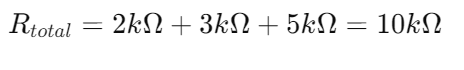
This cumulative resistance is significant for determining the circuit's impedance to current flow.
Law of Constant Current
In a series circuit, the current remains consistent across each component. This means the same current flows through every resistor, regardless of its resistance. This constancy is required to ensure the circuit functions predictably under varying loads. It also simplifies the analysis and design of series circuits. For instance, if the total current calculated using Ohm's Law is 1 mA, then each component in the series will experience this 1 mA of current.
Law of Voltage Division
The total voltage across the circuit is the sum of the voltage drops across each component. This principle follows Kirchhoff's Voltage Law, which asserts that the total sum of voltages around any closed loop in a circuit must be zero. To ensure correct operation and energy conservation, calculate the voltage drop across each resistor using  and check that the sum equals the source voltage.
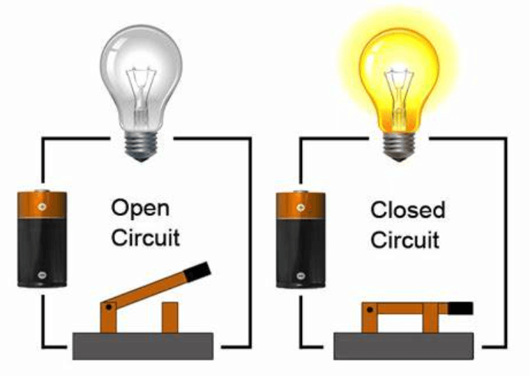
Figure 6: Open Circuit
Implications of an Open in Series Circuit Configurations
An open, or break, in a series circuit, stops the entire current flow. This occurs because the continuous path required for electric charge flow is disrupted. When there is an open, the current drops to zero immediately since electrical current cannot cross gaps in the circuit.
When an open occurs, the potential difference, or voltage, across the break equals the full source voltage. With no current flowing through the resistors, there is no voltage drop across them. Instead, the entire voltage supplied by the source appears across the open. Let's say, that in a circuit powered by a 9V battery, an open would result in a 9V measurement across the break.
This interruption stops the device or load in the circuit from functioning. It also poses a risk of damage due to the sudden exposure to full source voltage. Understanding the effects of an open circuit is decisive for troubleshooting and repair, as it helps identify the location and nature of circuit failures quickly.
Understanding Line Drop and Loss in Electrical Circuit Design
In circuit design, line drop, and line loss significantly influence the performance of electrical systems. These factors help ensure circuit efficiency and reliability, especially in long-distance power transmission or when dealing with sensitive electronic equipment.
Line Drop refers to the voltage reduction along a conductor due to its inherent resistance. Several factors determine the extent of this voltage drop:
Conductor Material: Commonly copper or aluminum for their good conductivity and cost-effectiveness.
Cross-Sectional Area: A smaller cross-sectional area results in a higher voltage drop for the same current.
Length of Conductor: Longer conductors exhibit higher voltage drops.
Line Loss pertains to energy lost as heat due to the resistance of the conductive path. Several factors influence this loss:
Material Properties and Dimensions: The material and size of the conductor affect resistance.
Condition of the Conductor: Oxidation, physical damage, or poor connections can increase resistance and energy losses.
How to minimize line voltage drops and line losses?
• Selecting Appropriate Materials and Sizes
Choose conductor materials and dimensions that minimize resistance.
• Optimizing Length of Conductive Paths
Shorter paths reduce resistance and associated losses.
• Maintaining Conductor Integrity
Ensure connections are secure and the conductor is in good condition.
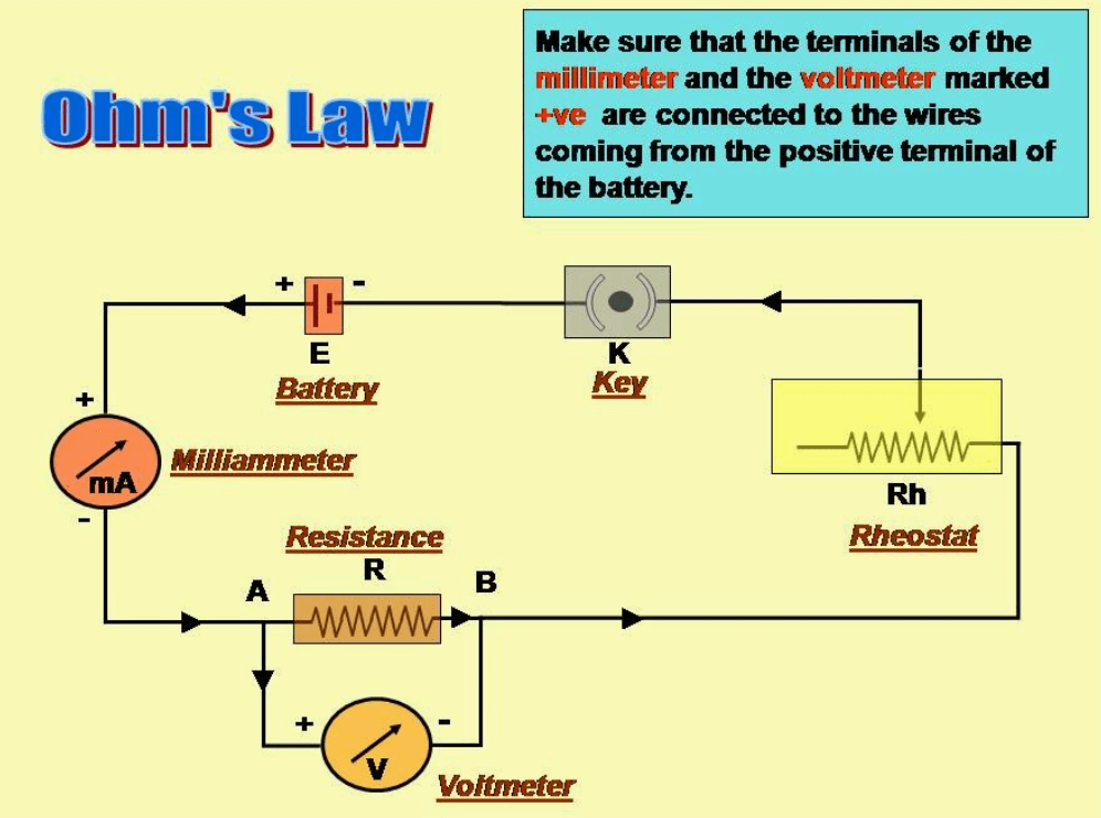
Figure 7: Application of Ohm's Law in Circuit
Effective Application of Ohm's Law in Circuit Analysis
Ohm's Law, given by (where is voltage, is current, and is resistance), is needed for analyzing electrical circuits. However, correct application is conclusive for accurate results. Misinterpretations or incorrect inputs, especially when mixing values from different parts of a circuit, can lead to significant errors.
The voltage (V), current (I), and resistance (R) values for each component or segment under examination must be correctly identified to conduct an accurate circuit analysis. This is because the configuration and characteristics of the circuit might affect the values of individual components and segments. Consistent measurements are required; for instance, when measuring the voltage across a resistor, ensure the circuit is powered and current is actively flowing through that resistor. In addition, understanding the context and arrangement of components is needed. In series circuits, the total resistance is the sum of individual resistances with the same current flowing through all components. Conversely, in parallel circuits, although the voltage across each branch remains constant, the total resistance and current distribution differ from those in series circuits
Steps to Apply Ohm's Law Correctly
Begin troubleshooting a circuit by identifying its configuration—whether it's series, parallel, or a combination of both. Then, calculate the total resistance using the appropriate formulas for the circuit type. Next, measure or calculate the voltage and current, ensuring that these measurements pertain to the same part of the circuit under identical conditions to maintain accuracy. By adhering to these guidelines, you ensure accurate circuit analysis and reliable conclusions about the circuit's behavior, performance, and safety. This disciplined application of Ohm's Law is helpful for both theoretical calculations and practical troubleshooting, making it requisite for electrical engineers and technicians.
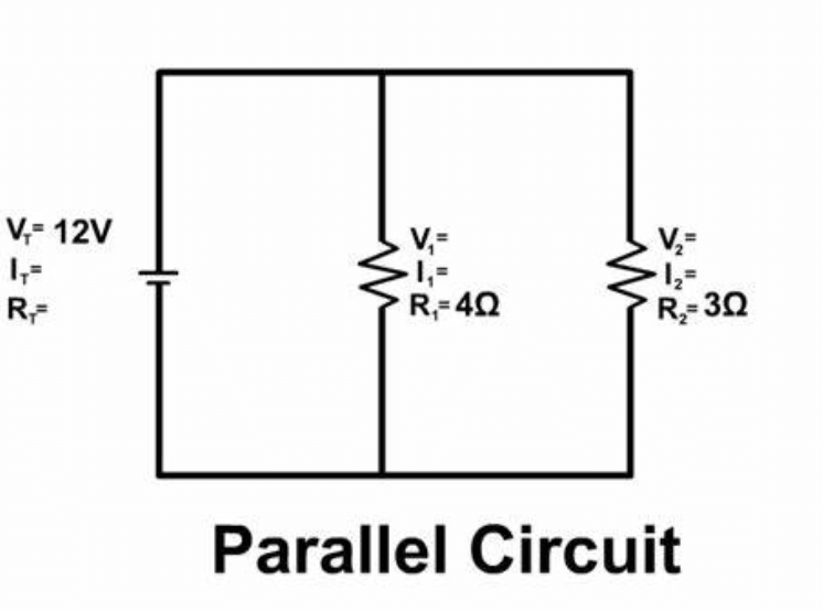
Figure 8: Simple Parallel Circuits
Investigating Simple Parallel Circuits
Parallel circuits differ fundamentally from series circuits in terms of voltage, current, and resistance distribution.
Voltage Uniformity
In parallel circuits, the voltage across each component or branch is identical and equal to the source voltage. This uniformity simplifies voltage analysis across individual components, as each one experiences the full voltage of the power supply directly.
Current Distribution
The total current flowing through a parallel circuit is the sum of the currents through each parallel branch. This occurs because the source current divides among the multiple pathways. Using Ohm's Law 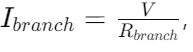 , allows you to calculate the current in each branch. The current through each branch depends on the resistance of that branch.
Resistance Calculation
The total resistance in a parallel circuit is less than the resistance of any individual branch. This is because multiple pathways provide more routes for current flow, reducing the overall opposition to current flow. The total resistance is calculated using the formula: 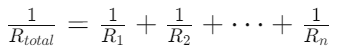 are the resistances of the individual branches.
Conclusion
The exploration of series circuits through the application of Ohm’s Law and other fundamental principles offers profound insights into the behavior of electrical systems. By dissecting the flow of current through single and multiple resistor setups, we gain a comprehensive understanding of how voltage, current, and resistance interplay to dictate circuit performance. The article not only reaffirms the consistency of current in series circuits—a decisive aspect for predicting electrical load behavior—but also highlights the practical applications of calculating total resistance and voltage drops, useful for circuit design and troubleshooting.
The extension of these principles to parallel circuits and the discussion on line loss and voltage drop in circuit design further enhance our ability to optimize, troubleshoot, and safely maintain electrical systems. This thorough analysis ensures that both budding and experienced engineers can apply these concepts to enhance the reliability, efficiency, and safety of electrical circuits, thus meeting the hard demands of modern electrical engineering.
Frequently Asked Questions [FAQ]
1. What is the application of Ohm's law in a series circuit?
Ohm's Law is fundamental in series circuits to determine the current flowing through the circuit when the total resistance and the applied voltage are known. It states that the current (I) through a conductor between two points is directly proportional to the voltage (V) across the two points and inversely proportional to the resistance (R) of the conductor. In a series circuit, where resistors are connected end-to-end, the total resistance is the sum of the individual resistances. Using Ohm's Law , you can calculate the single current value that flows through each component of the series circuit.
2. What is the application of a series circuit?
Series circuits are used in situations where the operation of one component affects all others connected in the circuit—think of old Christmas tree lights, where if one bulb failed, the entire string would go out. They are useful in applications requiring voltage dividers or current-limiting configurations, such as in basic electronic training, educational demonstrations, and simple electronic projects.
3. How does a series circuit work?
In a series circuit, all components are connected in a linear sequence, forming a single path for the current to flow. The same current flows through each component, starting from the power source, moving through each component, and returning to the power source. The total voltage across the circuit is divided among the components according to their resistance values.
4. What is the importance of a series circuit?
Series circuits are key for their simplicity and effectiveness in applications where uniform current is necessary across multiple components.
5. What are the three rules of a series circuit?
Current Rule: The current is the same through all components in the series. There is only one path for current flow, so whatever current enters a component must also leave it.
Voltage Rule: The total voltage across the series circuit is the sum of the voltages across each component. This is a consequence of the conservation of energy.
Resistance Rule: The total resistance of a series circuit is equal to the sum of the individual resistances of all components within the circuit. This affects how the total voltage is distributed and the magnitude of the current through the circuit.