A guide to the basics of D flip-flops - circuits, truth tables, types, advantages and limitations
In digital circuit design, D-type flip-flops are mainly used in applications that require highly stable and precise control of data flow. In order to deeply understand the behavior and characteristics of D-type flip-flops, constructing and analyzing a truth table is a critical step. Truth tables not only help designers foresee the response of circuits, but are also a fundamental tool for optimizing circuit design and fault diagnosis. In this article, we will explore in detail the specific behavior of the D-type flip-flop under different input and clock signal states, explain the response of its internal logic gates through examples, and how to formulate characteristic tables and characteristic equations based on this information to achieve more accurate circuit design and applications.Catalog
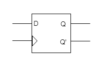
1. Working principle of D flip-flop
Before we get started, we need to build a truth table. The table clearly shows the response of a D flip-flop under different input (D) and clock signal conditions.
Case 1: D = 0
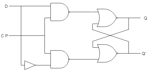
- • Gate 1 = 1
- • Gate 2 = 0
- • Gate 4 (Q(n+1)') = 1
- • Gate 3 (Q(n+1)) = 0
If D is low (0), the Q output will also be low (0). Since one of the inputs to Gate 4 is 0, and Gate 4 is a NAND gate, its output will be 1 regardless of the other inputs due to the nature of the NAND gate.
Case 2: D = 1
- • Gate 1 = 0
- • Gate 2 = 1
- • Gate 3 (Q(n+1)) = 1
- • Gate 4 (Q(n+1)') = 0
If D is high (1), the Q output will go high (1) regardless of its previous state. Since one of the inputs to Gate 3 is 0, and Gate 3 is a NAND gate, its output will be 1 regardless of the other inputs due to the nature of the NAND gate.
2. Situation analysis and truth table construction
When exploring how a D-type flip-flop responds to different input conditions, a very critical step is to construct and understand a truth table. This helps us predict circuit behavior and is the basis for troubleshooting and design optimization. First, we set the clock signal to a continuous high level (1). This means that the flip-flop responds to the input at D and updates the output at Q accordingly.
Analyze the situation when the D input is low (0):
- Operation: Set the D terminal to 0, observe and record the changes in the output.
- Logic Gate Response: In this setup, logic gate 1 is set to output a high level (1), while logic gate 2 outputs a low level (0).
- Output impact: Because the NAND gate (Gate4) receives at least one low level (0), according to the characteristics of the NAND gate, its output is high level (1). At the same time, the output of NAND gate 3 is low (0).
- Final Q output: This results in Q(n+1)' being high (1) and Q(n+1) being low (0).
Analyze the situation when the D input is high (1):
- Operation: Set D terminal to 1 at this time.
- Logic gate response: Gate 1 now outputs low (0) and gate 2 outputs high (1).
- Output Impact: At the same time, NAND gate 3 receives at least one low level (0), causing its output to become high (1), while the output of NAND gate 4 is low (0).
- Final Q output: The result is that Q(n+1) goes high (1), while Q(n+1)' remains low (0).
According to the above two situations, we wait until the truth table of the D flip-flop
|
CLK |
D |
Q(n+1) |
State |
|
– |
0 |
0 |
RESET |
|
– |
1 |
1 |
SET |
We can then write the characteristics table of the D flip-flop based on this truth table. In the truth table you can see that there is only one input D and one output Q(n+1). But in the feature table you will see that there are two inputs D and Q n, and one output Q(n+1).
It is clear from the above logic diagram that Qn and Qn' are two complementary outputs that also act as inputs to Gate3 and Gate4, so we consider Qn (i.e. the current state of the flip-flop) as an input, and Q(n+1) is the next state as the output.
After writing the characteristic table, we will draw a 2-variable K plot to derive the characteristic equation.
|
D |
Qn |
Q(n+1) |
|
0 |
0 |
0 |
|
0 |
1 |
0 |
|
1 |
0 |
1 |
|
1 |
1 |
1 |
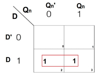
From the K-map you get 2 pairs. After solving both, we get the following characteristic equation:
Q(n+1) = D
3. Types of D-type flip-flops
Depending on how the clock signal is received, D flip-flops can be divided into two categories: level-triggered and edge-triggered. Each type has specific functions and suitable applications.
Level-triggered D flip-flop (latch)
Level-triggered D flip-flops, commonly known as latches, are sensitive to the high and low levels of the clock signal. Here's how it works:
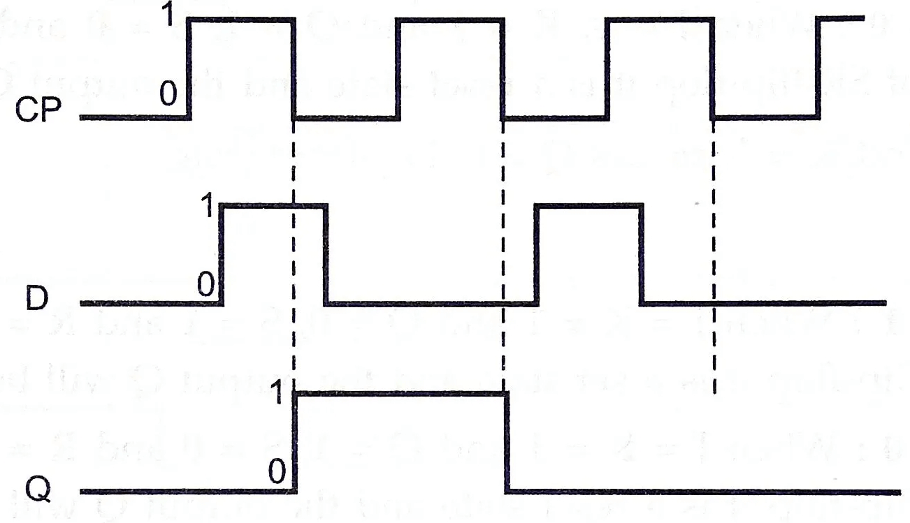
- • When the clock signal is set high (1) and the input to the D terminal is changed, the output of the Q terminal reflects the same state almost immediately. This means that any changes at D will be reflected directly at Q.
- • When the clock signal is low (0), the output at Q remains the same regardless of what happens to the D terminal.
This type of trigger is ideal for applications that require stable data output, such as temporarily storing data in a data acquisition system. The latch retains its state until the clock signal changes, ensuring consistency of the data output.
Positive edge triggered D flip-flop
A positive edge-triggered D flip-flop responds only when the clock signal transitions from low to high. Learn how it works:
- • Focus on monitoring the rising edge of the clock signal.
- • Immediately after detecting the rising edge, the data on the D terminal is transferred to the Q terminal.
This type of flip-flop is suitable for applications that require precise capture of data at a specific moment, typically in synchronous circuits.
Negative edge triggered D flip-flop
The negative edge triggered D flip-flop is the opposite of the positive edge triggered type and responds to the falling edge of the clock signal. Here's how it works:
- • Monitor the clock signal for falling edges.
- • When the clock signal transitions from high level to low level, the current state of D terminal is captured and transferred to Q terminal.
This type of flip-flop is used in applications where data needs to be captured at the exact moment the clock signal falls to ensure precise timing in various digital systems.
4. Advantages and limitations of D-type flip-flops
Advantages
Simplified design: The D flip-flop has a single data input, simplifying the overall circuit design. This reduces connection errors and speeds up layout implementation, especially during rapid prototyping of complex circuits. When working on complex designs, fewer connections mean less potential for errors, making the process smoother and more efficient.
Stability and Reliability: The design of the D flip-flop eliminates feedback loops, making it less susceptible to race conditions and noise. For example, the robustness of the D flip-flop ensures consistent performance in environments with severe electrical interference.
Low power consumption: D flip-flops consume less power compared to other flip-flops. This extends battery life and reduces operating costs, making it ideal for portable and remote monitoring equipment. In battery-powered systems, using a D flip-flop can significantly extend the life of the device.
Bistable Operation: D flip-flops can maintain their state without changing the input signal, making them very useful in applications that require long-term state retention, which can be very valuable for automated control and safety systems.
Limitations
Lack of feedback control: D flip-flops have no built-in feedback path, making them unsuitable for systems that require dynamic output adjustment, such as servo motor control or adaptive signal processing. This limitation can be important in applications that require continuous feedback to adjust the output in real time.
Propagation Delay: Although D flip-flops generally respond quickly, they still exhibit some propagation delay. In high-speed digital communications systems, this delay can cause data synchronization problems. Designers must account for this delay to avoid timing errors in fast-paced environments.
Scalability Issues: Although D flip-flops are suitable for many standard applications, they can face challenges when scaling to more complex digital systems. Handling more concurrent signals or higher data rates can complicate system design, increasing difficulty and cost. As system complexity increases, the limitations of D flip-flops in managing large amounts of signal processing become more apparent.
5. Application areas
D flip-flops have a variety of practical applications in digital systems. Some key uses include:
Shift Registers: By cascading multiple D flip-flops, you can create shift registers that store and shift data in digital systems. Shift registers are commonly used in serial communication protocols such as UART, SPI, and I2C. In practice, you can use them to convert data between serial and parallel forms, thus facilitating efficient data transfer.
State Machine: D flip-flops are an integral part of implementing a state machine, which controls the sequence of events in a digital system. State machines are ubiquitous in control systems, automotive applications, and industrial automation. For example, in an automated production line, a state machine can manage the sequence of operations, ensuring that each step is executed in order.
Counters: Combining D flip-flops with other digital logic gates can create binary counters that count up or down depending on the design requirements. These counters are crucial in real-time applications such as timers and clocks. For example, in a digital clock, a counter helps track the passage of time by counting clock pulses.
Data Storage: D flip-flops can store temporary data in digital systems. They are often used with other storage elements to build more complex storage systems. For example, in a computer's memory architecture, a D flip-flop might temporarily store bits of data as part of a larger memory structure.
6. Summary
Whether in various practical applications such as data storage, state control, or precise timing, D-type flip-flops have demonstrated their powerful functionality. Their design simplifies circuit complexity, improves system stability and reliability, and reduces power consumption. As a designer, understanding the detailed working mechanisms and potential applications of these flip-flops will help you better utilize these devices to solve specific technical challenges, thereby designing more efficient and reliable digital systems.
I hope this article is helpful to you. If you need to explore more technical knowledge about D-type flip-flops, you can contact us.
Frequently Asked Questions [FAQ]
1. How does a D flip-flop work?
D flip-flop (D flip-flop) is an electronic component mainly used to store signal states. On the rising edge of the clock signal, the D flip-flop reads and latches the signal state at the D input until the next rising edge of the clock signal. Specifically, if the D terminal input is high level (1), then the output Q will also become high level after the clock pulse; if the D terminal is low level (0), the output Q will become low level. .
2. What does the D in D flip-flop stand for?
The "D" in D flip-flop stands for "Data", which means that this flip-flop is mainly used for the storage and transmission of data.
3. What is the output frequency of the D flip-flop?
The output frequency of a D flip-flop is equal to half the input clock signal. This is because the D flip-flop only responds to one edge of the signal (usually the rising edge) in each clock cycle, so the data is updated only once every two clock cycles.
4. What is the difference between a D flip-flop and a T flip-flop?
The main difference between D flip-flop and T flip-flop is their function and purpose. D flip-flops are used to latch a single data bit and are ideal for data storage and signal synchronization. The T flip-flop (Toggle flip-flop) switches its output state at each clock pulse. If the input is high level, the output will switch from high level to low level, or from low level to high level. flat, which makes T flip-flops commonly used in counter design.
5. Why do we use a D flip-flop instead of the SR flip-flop?
We prefer to use D flip-flops instead of SR flip-flops (Set-Reset flip-flop), mainly because D flip-flops are simpler and safer in design. The SR flip-flop needs to control the set and reset signals at the same time. If both inputs are high at the same time, it will cause the output to enter an unstable state, which may cause problems in practical applications. In contrast, the D flip-flop requires only one data input, is easier to control, and does not appear unstable. Therefore, the D flip-flop is more preferred in applications that require stable data storage and simplified design.