TL431 Shunt Regulator: Pinout, Applications, and Datasheet
This article delves into the intricacies of diagnosing and replacing a faulty TL431, a task that holds immense importance for ensuring the smooth operation of electronic circuits. Through a comprehensive exploration of the TL431, from its properties to its integration in various applications like power supplies and automotive systems, we aim to equip with the knowledge to handle this component with precision. Insights into related components such as semiconductors, capacitors, resistors, and integrated circuits will broaden the understanding needed for effective troubleshooting and enhancement of circuit performance.Catalog
TL431 Shunt Regulator Overview
TL431 is an incredibly versatile and adjustable shunt regulator capable of operating within a 2.5 to 36V range. Known for its blend of high performance and affordability, it plays a role in many applications such as precision switching power supplies, linear regulated power supplies, voltage comparators, power supply monitors, delay circuits, and constant current sources. The device supports a wide operating current range of 1 to 100 mA and features a dynamic impedance of 0.22 Ω. This enables temperature stability from -40°C to +125°C, which is beneficial for automotive applications. The output voltage is adjustable between 2.5 and 36 V via two external resistors, providing precise voltage regulation.
TL431 Equivalents and Alternatives
• TL431IZT
• TL431IZ
• TL431CZT
• TL431ILP
• TL431CZ
• KA431
• μA431
• LM431
• YL431
• S431
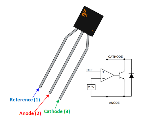
TL431 Pinout Configuration
|
Pin Number |
Pin Name |
Description |
|
1 |
Ref (Reference Pin) |
The Reference pin is instrumental in determining the
output voltage. By connecting an external resistor network, the reference
voltage can be meticulously adjusted to meet specific circuit demands. This
pin allows to tailor the regulator for a diverse range of applications. |
|
2 |
Anode Pin |
The Anode pin constitutes the low-side connection within
the TL431. Integrating this pin requires vigilance to ensure superior
functionality. Proper grounding and minimizing noise interference are
important elements to consider while designing circuits with this component. |
|
3 |
Cathode Pin |
The Cathode pin serves as the high-side connection where
the regulated output is obtained. Its integration demands careful attention
to ensure accurate coupling with the rest of the circuit. Stable voltage
regulation hinges on the precision of connections related to the Cathode pin. |
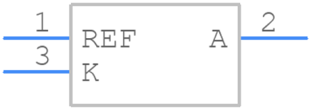
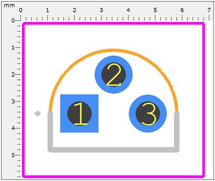
TL431 Symbol, Footprint, and CAD Model
Features of TL431
Automotive-Grade Qualification
The TL431 is engineered to meet the rigorous AEC-Q100 standard, affirming its durability and reliability in vehicular settings. This qualification emphasizes the component's resilience to demanding automotive conditions, such as frequent temperature fluctuations, persistent vibrations, and electrical noise. Such robustness makes the TL431 a trusted component in automotive systems, where reliability is non-negotiable given the potential safety ramifications of component failures.
Adjustable Output Voltage Range
The TL431 provides an adjustable output voltage from 2.5V to 36V, offering versatility in a wide array of electronic designs. This feature allows the freedom to customize the device to meet specific application requirements. From low-power mobile devices to high-voltage industrial systems, this adjustability is advantageous. Practical applications often reveal that fine-tuning the output voltage can lead to improved energy efficiency and prolonged battery life in portable electronics.
Broad Current Capability
The TL431 supports a current range spanning from 1mA to 100mA, making it suitable for a diverse range of current requirements. This flexibility renders it useful in various applications such as power regulation circuits, battery chargers, and reference voltage sources. Many industries appreciate this range for ensuring that their designs perform optimally and remain within safe operational boundaries.
Low Output Impedance
Boasting an output impedance of 0.22 Ω, the TL431 ensures minimal resistance at the output, which contributes to the stability and precision of voltage regulation. Low impedance is good for maintaining a consistent output voltage despite varying loads. In practical design scenarios, others aim for low-output impedance to reduce the influence of noise and ripple, resulting in clearer, more stable signals in sensitive electronic circuits.
High Voltage Precision
The TL431 is available with voltage precision options of 1% and 2%, for applications requiring exact voltage references like analog-to-digital converters and sensor interfaces. The precision of voltage regulation directly impacts the accuracy of the overall system. In both electronics and high-precision industrial equipment, accurate voltage regulation enhances performance and ensures long-term reliability and consistency.
Extensive Operating Temperature Range
Operating efficiently within a temperature range of -40°C to +125°C, the TL431 is well-suited for extreme environmental conditions. Whether in cold storage facilities or high-temperature industrial processes, this capability ensures consistent performance. This translates to fewer concerns about thermal-induced errors, thereby maintaining the integrity and reliability of the end product in a variety of environments.
TL431IZ Specifications
|
Type |
Parameter |
|
Lifecycle Status |
ACTIVE (Last Updated: 7 months ago) |
|
Mount |
Through Hole |
|
Package / Case |
TO-226-2, TO-92-2 (TO-226AC) |
|
Operating Temperature |
-40°C to 105°C TA |
|
Tolerance |
±2.21% |
|
Part Status |
Active |
|
Number of Terminations |
3 |
|
Temperature Coefficient |
100 ppm/°C |
|
Terminal Position |
BOTTOM |
|
Base Part Number |
T1431 |
|
Number of Outputs |
1 |
|
Output Type |
Adjustable |
|
Number of Channels |
1 |
|
Analog IC - Other Type |
THREE TERMINAL VOLTAGE REFERENCE |
|
Max Output Voltage |
36V |
|
Reference Voltage |
2.495V |
|
Min Output Voltage |
2.495V |
|
Current - Cathode |
1mA |
|
RoHS Status |
RoHS3 Compliant |
|
Factory Lead Time |
8 Weeks |
|
Mounting Type |
Through Hole |
|
Number of Pins |
3 |
|
Packaging |
Bulk |
|
JESD-609 Code |
e3 |
|
Moisture Sensitivity Level (MSL) |
1 (Unlimited) |
|
ECCN Code |
EAR99 |
|
Terminal Finish |
Matte Tin (Sn) - annealed |
|
Number of Functions |
1 |
|
Pin Count |
3 |
|
Output Voltage |
36V |
|
Max Output Current |
100mA |
|
Trim/Adjustable Output |
YES |
|
Nominal Supply Current |
1mA |
|
Max Input Voltage |
37V |
|
Reference Type |
Shunt |
|
Temp Coeff of Voltage-Max |
82.924 ppm/°C |
|
Radiation Hardening |
No |
|
Lead Free |
Yes |
Functional Block Diagram of TL431
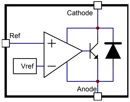
Internal Circuitry Components
The internal voltage reference provides a stable output voltage. Such stability is a result of meticulous design and material selection. It shows that a stable voltage reference enhances power management efficiency in electronic systems. This impact is evident in precision applications, such as voltage regulators in sensitive measurement devices. The op-amp in TL431 compares the voltage at the reference pin with the divided output voltage, regulating the pass element accordingly. Its precision and response time, influencing the regulator's adaptability to load changes. In practical scenarios, optimizing the op-amp's selection, configuration, and biasing conditions ensures a quick response to dynamic loads, boosting overall system performance. The series pass element, acting as a variable resistor modulated by the op-amp control signal, adjusts the current passing through the device, stabilizing the output voltage. Practical designs often involve selecting high-gain pass elements for finer control over output voltage. Such precision is valuable in applications with strict voltage tolerances.
Control Feedback Loop
The control feedback loop is central to the TL431's regulation capabilities, swiftly correcting any output voltage deviations. The feedback network uses carefully chosen resistors and capacitors to achieve the desired division ratio of the output voltage, which is then fed back to the operational amplifier's input. Adjusting the feedback network in applications can fine-tune the regulator's output, thus attaining higher accuracy in voltage-sensitive applications. Compensation components like capacitors integrate into the system to stabilize the loop and prevent oscillations. Techniques such as phase margin adjustments using capacitive loading are frequently employed to ensure robust and stable operation. This approach is needed in systems where the TL431 regulates dynamically changing loads.
Methods to Accurately Measure the TL431
Assessing the Zener Diode's Forward and Reverse Resistance
To evaluate both the forward and reverse resistance of a Zener diode, begin by adjusting your multimeter to the Rxlk range. Attach the black probe to the anode (A) and the red probe to the cathode (K). Initiate the measurement by recording the forward resistance, then proceed to capture the reverse resistance. A functional Zener diode demonstrates low forward resistance and infinite reverse resistance. In practice, it is need to ensure firm connections of the probes to avoid erroneous readings. Intermittent contact can result in fluctuating measurements, necessitating steady hands and secure probe connections.
Evaluating Forward and Reverse Resistance of Resistor (R) Relative to A and K Poles
Switch the multimeter to the Rxlk setting, and attach the black probe to the resistor (R) and the red probe to the anode (A). The expected resistance should be approximately 35xlkΩ. When reversing the probes so the black is on the anode and the red on the resistor, the resistance should read around 10xlkΩ. When measuring resistance from R to K, readings should approximate 11xlkΩ in one direction and infinite in the reverse. Observations suggest these values may slightly vary due to environmental influences, such as temperature or humidity, affecting component behavior subtly.
Measuring K Pole's Forward and Reverse Resistance to Other Poles
Follow the same steps for measuring the forward and reverse resistance between the K pole and other related poles. Ensure your multimeter remains set at Rxlk for consistent measurements. Grounding oneself before handling sensitive electronic components, like the TL431, can prevent static damage and yield more accurate readings.
Evaluating the Performance of TL431
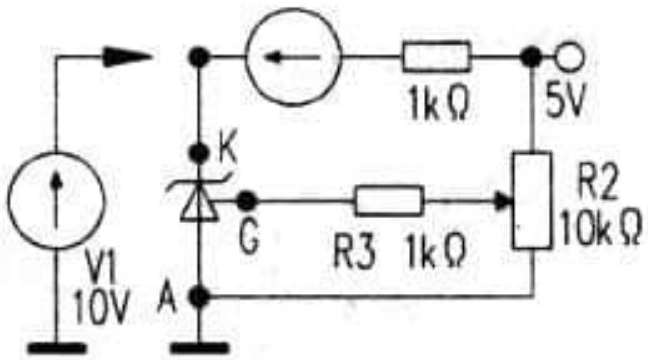
To achieve an exhaustive evaluation of TL431, a circuit equipped with a variable power supply spanning 0 to 20V should be established. Start by connecting an ammeter in series with the K pole and the power supply to gauge current fluctuations. Concurrently, link a voltmeter between the K (Cathode) and A (Anode) to monitor output voltage variations. Setting the potentiometer near its mid-value can offer insightful observations of the voltage behavior between K and ground. A correctly functioning TL431 will display two distinct states: a low voltage state around 2V and a high voltage state almost equal to the power supply voltage. The transition between these states validates the device's performance.
An effective test will show the K pole toggling smoothly between high and low states as the supply voltage fluctuates. This on/off switching action confirms the TL431’s ability to reconfigure the duty cycle, ensuring stable voltage output. Furthermore, considering factors such as temperature and load variations provides deeper insights into the TL431's reliability and longevity in practical applications. The results of these tests not only affirm the immediate functionality of the TL431 but also help in preemptively identifying potential long-term reliability issues.
Applications of TL431
Power Supply Regulation
In power supply regulation, the TL431 shunt regulator has a main role. It stabilizes voltage in power supplies, ensuring consistent and reliable performance. This component is not limited to merely maintaining voltage levels, it enhances transient response, it improves loop response, and boosts efficiency and robustness in uninterruptible power supplies (UPS) and AC-DC converters.
Industrial Applications
Industrial settings, marked by challenging operational environments, see utility in TL431. It is used in numerous applications including motor control, sensor interfacing, and industrial automation systems. The TL431 maintains precision under fluctuating environmental conditions. It enhances stability and accuracy in complex machinery for accurate control and monitoring. It improves sensor output stability in feedback loops within complex control systems.
Automotive Systems
Automotive systems require components that can sustain high performance under varying thermal and electrical conditions, where TL431 shines. It is extensively used in automotive electronics such as Engine Control Units (ECUs), electric power steering systems, and battery management systems. Due to its robustness and precision, TL431 ensures reliability in automotive functions, maintaining safety and efficiency. Its role is notable in hybrid and electric vehicles, where precise voltage regulation is great for battery longevity and overall system performance.
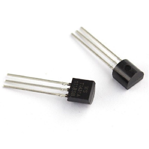
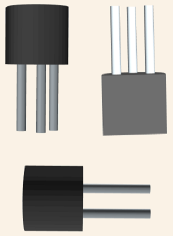
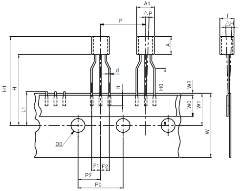
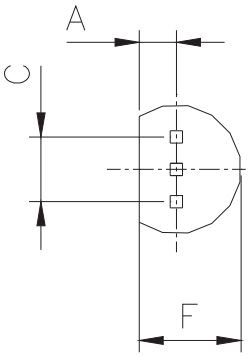
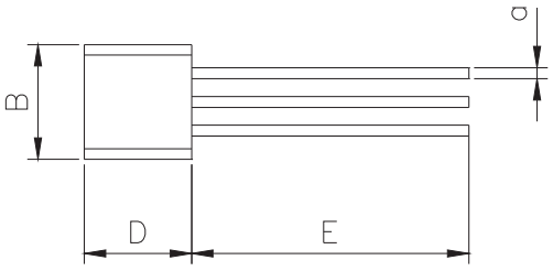
TL431 Package
TL431 Manufacturer Information
STMicroelectronics, renowned in the semiconductor realm, is celebrated for crafting integrated solutions tailored to deliver peak performance. With a vast array of products, the company consistently aligns with the demanding standards of diverse industries, reflecting its commitment through excellence. STMicroelectronics stands as a strong force in the semiconductor landscape. Products like the TL431 illustrate their dedication to precision, reliability, and innovation, emphasizing their role in shaping both contemporary and future technological landscapes.
Datasheet PDF
TL431 Datasheets:
TL431IZ Datasheets:
Mult Dev Adv Material Notice 8/Apr/2019.pdf
Mult Dev Mold Comp Chg 6/Jul/2019.pdf
Frequently Asked Questions [FAQ]
1. How many pins does the TL431IZ have?
The TL431IZ consists of three pins. They have noted that its simplicity in pin configuration enhances its reliability in various applications.
2. What is the operating temperature range of the TL431IZ?
The TL431IZ functions effectively within temperatures ranging from -40°C to 105°C. This operational range assures users of its performance even in extreme thermal environments.
3. What is the property of the TL431?
The TL431 is recognized for its stable adjustable shunt voltage reference. This quality not only allows it to perform over a broad temperature spectrum but also makes it a favored choice on seeking dependable voltage control.
4. What are the practical applications of the TL431?
The TL431 finds its primary use in switching power supplies. It provides a stable voltage reference. It offers a reliable feedback mechanism. This component improves power supply stabilization.
5. What is the TL431 transistor?
The TL431 functions as a programmable regulator diode, akin to an adjustable Zener diode. Its capacity to adapt to various circuit designs renders it a versatile tool in voltage regulation tasks. This adaptability appeals to many tasked with creating efficient and flexible electronic systems.
6. How does a shunt regulator operate?
A shunt regulator preserves a constant voltage by directing surplus current to the ground. This method is great for protecting sensitive electronic components from voltage irregularities. Others frequently commend shunt regulators for their role in achieving robust voltage stability, a factor that contributes to the durability and reliability of electronic systems.